 Fraens
You can download all the files you need for building here: Download the Braiding machine
Description of the machine:
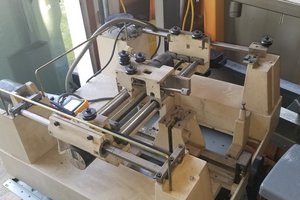
About 1 year ago I built the first prototype of the braiding machine.
This was my first prototype (A video about this one: Old Version)
The coil carriers move on a circular path around the braiding point. The distance to the braiding point changes depending on the position of the coil carriers. The ropes must remain taut at each position to get a clean braid. This is done by a tensioning mechanism that works with a spring.
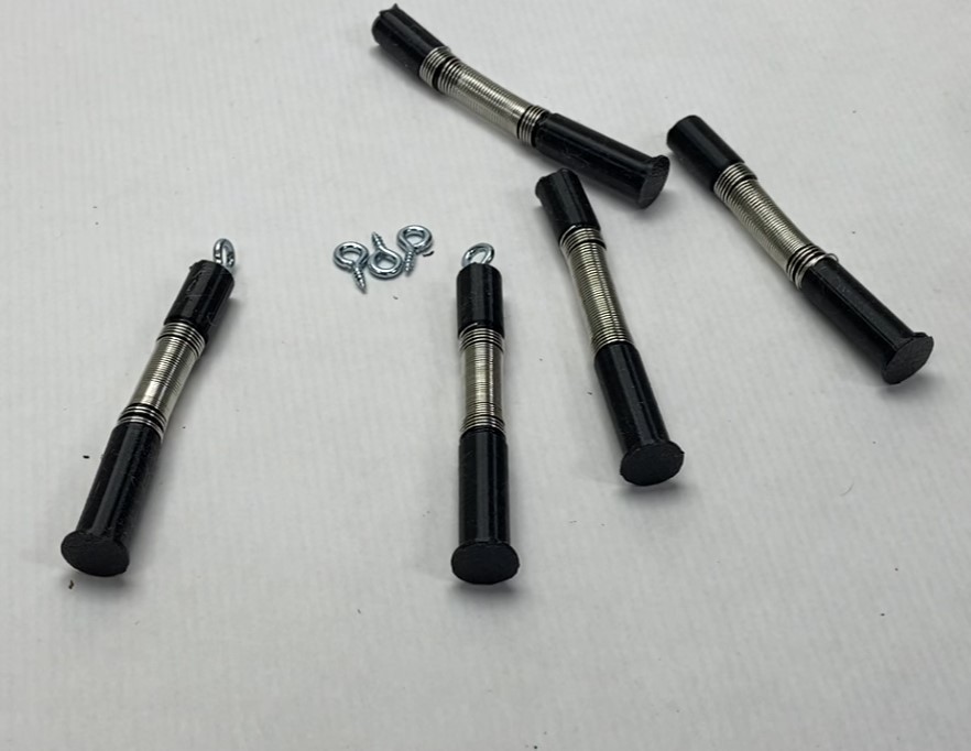
To prevent the rope tension from unthreading the spool, a locking lever is installed that releases the spool piece by piece.
To have as little friction as possible at the deflection points, all rope bushings are provided with eyelets.

The spool carriers travel on a path around the braiding point. In the process, the paths of the ropes cross. This results in a round braid.
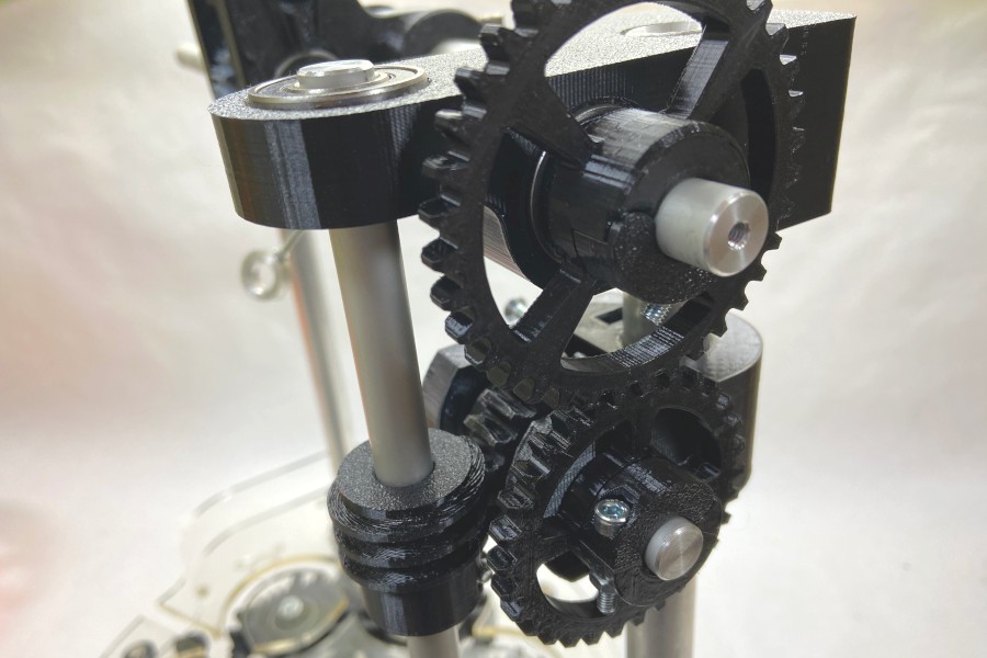
The spool carriers are pushed along in the tracks by so-called horn gears. At the crossing points, the spool carrier changes from one gear to the next. This is a simple but ingenious technique. All gears have involute gearing. This tooth form reduces the friction between the teeth. The base plates are made of acrylic glass.

The take-off unit is driven by a worm gear. The trigger speed can be adjusted via the gear ratio. A slow speed makes a closed braid. A fast speed gives an open braid. Here you can experiment.
The machine is built for a maximum of 12 spool carriers. However, fewer can also be used. Build as many spool carriers as you like. It makes sense to have a few more spools for a quick exchange on the machine.
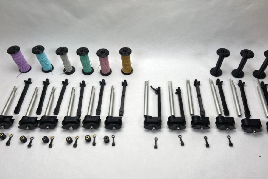
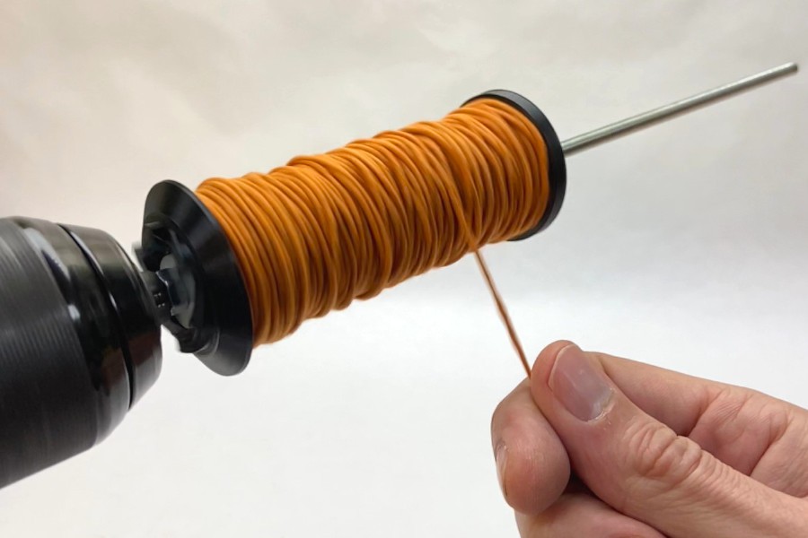
I use a cordless drill to wind the coils. For clamping the coil, there are cone pieces that are pushed onto a threaded rod. The correct winding technique is essential to have a good running machine. The line must always cross over on the spool so that it gets stuck. The cords should not slip into each other. This is done with a back and forth movement.
The machine is driven by 24V geared motor. Some drive power is needed to move the coils. The power needed to pull the braided rope is not to be underestimated. In addition you have high friction forces on the spool carriers that have to be overcome. You can choose to run the machine with one or two motors. If you use 6 or less spool carriers, you can install one motor. If you use the machine with 12 spool carriers, 2 motors are needed. To control the speed of the motors, a simple PWM controller is needed. Both motors can thus be operated in synchronism.
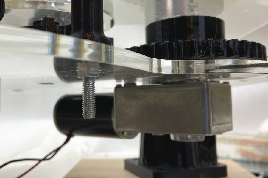
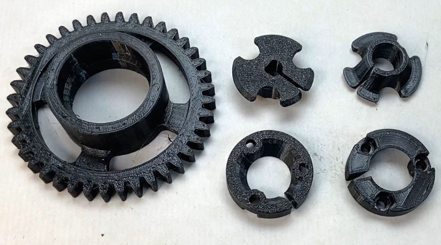
The connection of the motor and the drive gear is solved by a 3D-printed clamping set. The clamping set has the task of connecting the drive gear with the motor and the shaft to the worm gear. Developing a 3D printed clamping set took me a lot of time. The difficulty is to center the gear on the motor shaft without it wobbling.
A core material can be fed via the center tube. Thus, a thin cable or a plastic core can be fed. It is also possible to braid a previously braided rope again. This allows you to create a thick cord. Depending on the diameter of the core material, you have to adjust the take-off speed.

Manufacturing process:
- The 3D printing:
Approximately 60-100 hours of printing time is required. You will need about 1.5kg of filament. However, this is only a rough estimate. Depending on the settings with which you print the parts, of course, other values.

- Production of the springs:
- I wind the springs on my lathe. Here I have an automatic feed that keeps the pitch of the spring exactly. This ensures that a uniform spring is created. But you can also wind the spring with an acoustic screwdriver or something similar.
![]()

- Acrylic base plate with the tracks:
My acrylic plate is laser cut. You can cut it out with a lot of patience and a steady hand with a decubier saw. You can also mill the base plate.
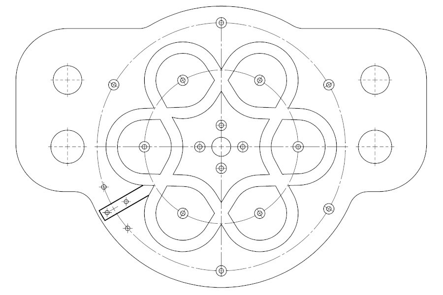
Here you can see the overview drawing of the machine:
... Read more »


 Ricky Zhang
 Boris van Galvin
 Capt. Flatus O'Flaherty ☠
 Joseph Eoff
Bravo! This is a real tour de force of a design, including the take up section and the bobbin holders and tensioners. Thank you for creating and sharing.