Pradeeplogu
Story:
LoRa is a wireless network solution that emerged in the field of IoT. It is a low-power and wide-area network with low power consumption and a long transmission range. In this project, I’m going to explain how to build a LoRa-powered solar power monitoring system with the help of cellular IoT. The data from the photovoltaic solar panel is sensed and collected from sensors and transmitted using LoRa modules. Further, the data is uploaded to a Qubitro cloud portal via Blues Wireless cellular IoT notecards in the base station. Using Qubitro API we can monitor and analyze the solar PV system performance.
Hardware Requirements:
- LTE-M Notecard Global
- Notecarrier A with LiPo, Solar, and Qwiic Connectors
- Xiao RP2040
- LoRa Wio-E5
- Customized PCB from Seeed Fusion Service
- BH1750 - Light Intensity Sensor Module
- Gravity: I2C Digital Wattmeter
- Grove - Temperature & Humidity Sensor (SHT40)
Software:
Flow Overview:

To monitor the solar PV cells, here I’m using a Gravity I2C Wattmeter sensor. Through this, we can monitor the generated voltage and consumed power and also the load current. Also, I need to monitor the solar light intensity and the temperature to analyze the generated voltage vs solar environment status. For this, I have used the BH1750 Light Intensity sensor and Grove Temperature and Humidity sensor.
Now, we are ready with the sensing unit. Next, let’s design a system that can collect the sensor data and transfer it via LoRa. To design this system, I have used Seeedstudio Fusion PCB service. And they also offer a completely free PCB for your LoRa Wio E5 design. Here is the 3D image of my design.

In this design, I have added Xiao RP2040 with LoRa E5.
Now, we can connect all those sensors with Xiao RP2040 and transfer them via LoRa E5. That’s all about the sender node. Next, we have to build a receiver to receive the data from our sender node and then publish it to the cloud. Here I'm also going to use the same PCB design with Blues Notecard and Notecarriers. Xiao +LoRa E5 PCB will receive the data from the sender, and it will transfer the data via Blues Cellular Notecard.

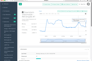
Finally, we can use Qubitro and Qubitro API to share and visualize our solar PV data.
Hardware Connection:

On the transmitter side connect all three sensors with the XIAO RP2040 by using the I2C port. And the Wio E5 is already connected to the Xiao RP2040 by using the UART port.

On the receiver side connect the Blues Wireless notecard with the XIAO RP2040 using the I2C port. And the Wio E5 is already connected by using the UART port. The receiver node will receive the data via LoRa and transfer the data to the cloud by using the Blues Notecard.
Let’s Bring Up the Board First:
Seeed Studio also offers free functional testing of your PCB boards. For my design, I have also done a base functional test to check my board is fine. In my design, I have added a Wio E5 with Xiao RP2040 by using the UART lines. And we can easily communicate with the Wio E5 using AT commands. So, if my Wio E5 responds to our AT commands, it means all good. It means technically “I’m alive ''. On the production site, we can’t use the serial monitor to check the PCB's response, so I have planned to implement some LEDs on it. But luckily the Xiao RP2040 has an onboard RGB led. We can directly use that to do our functional testing. Here is my simple Arduino sketch.
#include <Adafruit_NeoPixel.h>

int Power = 11;
int PIN  = 12;
#define NUMPIXELS 1

Adafruit_NeoPixel pixels(NUMPIXELS, PIN, NEO_GRB + NEO_KHZ800);

static char recv_buf[512];

int counter = 0;

static int at_send_check_response(char *p_ack, int timeout_ms, char *p_cmd, ...)
{
  int ch;
  int num = 0;
  int index = 0;
  int startMillis = 0;
  va_list args;
  memset(recv_buf, 0, sizeof(recv_buf));
  va_start(args, p_cmd);
  Serial1.print(p_cmd);
  Serial.print(p_cmd);
  va_end(args);
  delay(200);
 startMillis...
Read more »
 Luke Beno
 Siddhant Choyal