 Jon
JonWant to get one?
If you want to get a Smart Powermeter set, you can get it on the Elecrow's marketplace :

The story behind
Since my electric power provider only sends the consumtpion data (and invoice attached) once each a few months, it should be three but it's highly irregular, and I had enough space in my electricity distribution panel, I embarked on a mission to create my very own solution – the Smart Powermeter.
The Smart Powermeter V1R1
My first design (V1R1), and the one that I still have operative, was based on an external board: the TTGO T-Display. This board, besides embedding the powerful ESP32, has a small 1.14'' full-color LCD, which I looked forward to programming with a power indicator gauge.
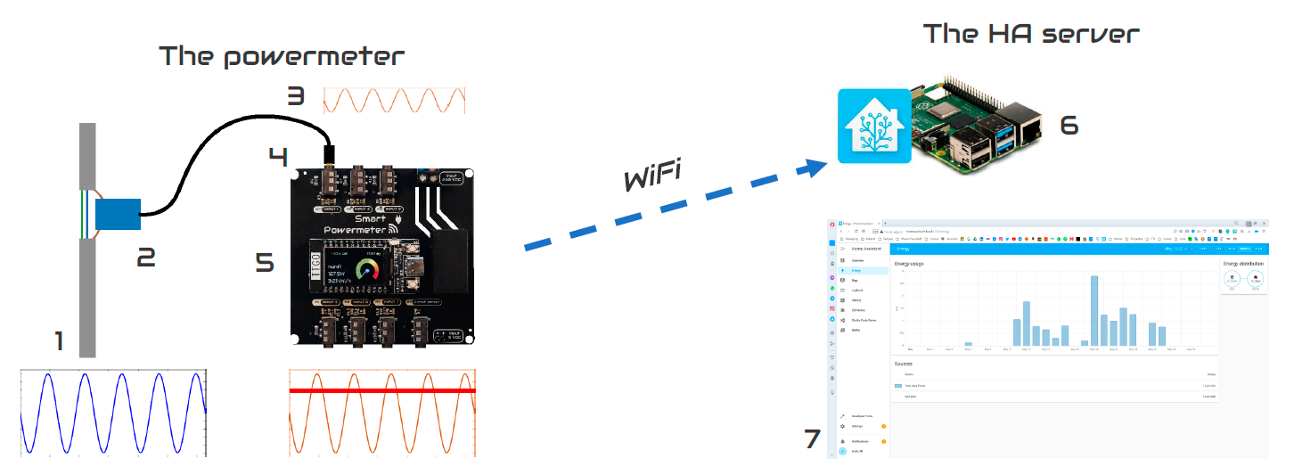
In a way, the V1R1, behaved as an Arduino Shield, providing the TTGO board with the signals from the CT clamps already conditioned, to fill in the range of the 0-3.3V, as well as a 5v regulated power supply.
A deeper understanding of how the conditioning circuit works can be found in the documentation of openenergymonitor, but to summarize it, the CT clamp, which needs to only surround one wire (easy to achieve on the electric closet), will convert the induced magnetic field, proportional to the AC current flowing through the conductor, into another current on the CT clamp. After all, CT stands for Current Transformer, so the coefficient of conversion will be given as a known factor of the CT clamp (generally printed on the device, like 50A:10mA).
Since the microcontroller cannot read directly any current, the first step is to convert it into voltage, easy with Ohm's law. So given a fixed resistor (known as a burden resistor), the voltage will be proportional to the intensity.
Now, the next challenge to measure the signal is to convert the +- volts from the raw signal, into a 0-3.3V range that the microcontroller can read. By replacing the connection of the CT lead to ground with a connection to a source voltage that is half the supply voltage (3.3V), the CT output voltage will oscillate around 1.65V, ensuring that it remains in the positive range.
For my application, I just wanted the RMS (Root-Mean-Square), representative of the average value of a complete cycle. But if you might want to look into power factor and offsets between phases, the hardware on the ESP32 should allow a high enough sampling rate to get a good view of the signal.
Since I used ESPHome, and there is a very good implementation for CT sensors on it, I didn't have to fight too much with the sample rate settings or the RMS calculations. However, after testing the instrumentation at different power loads, I realized, with the help of a handheld ammeter, that without a calibration the displayed values were not very accurate, so I applied a linear calibration.
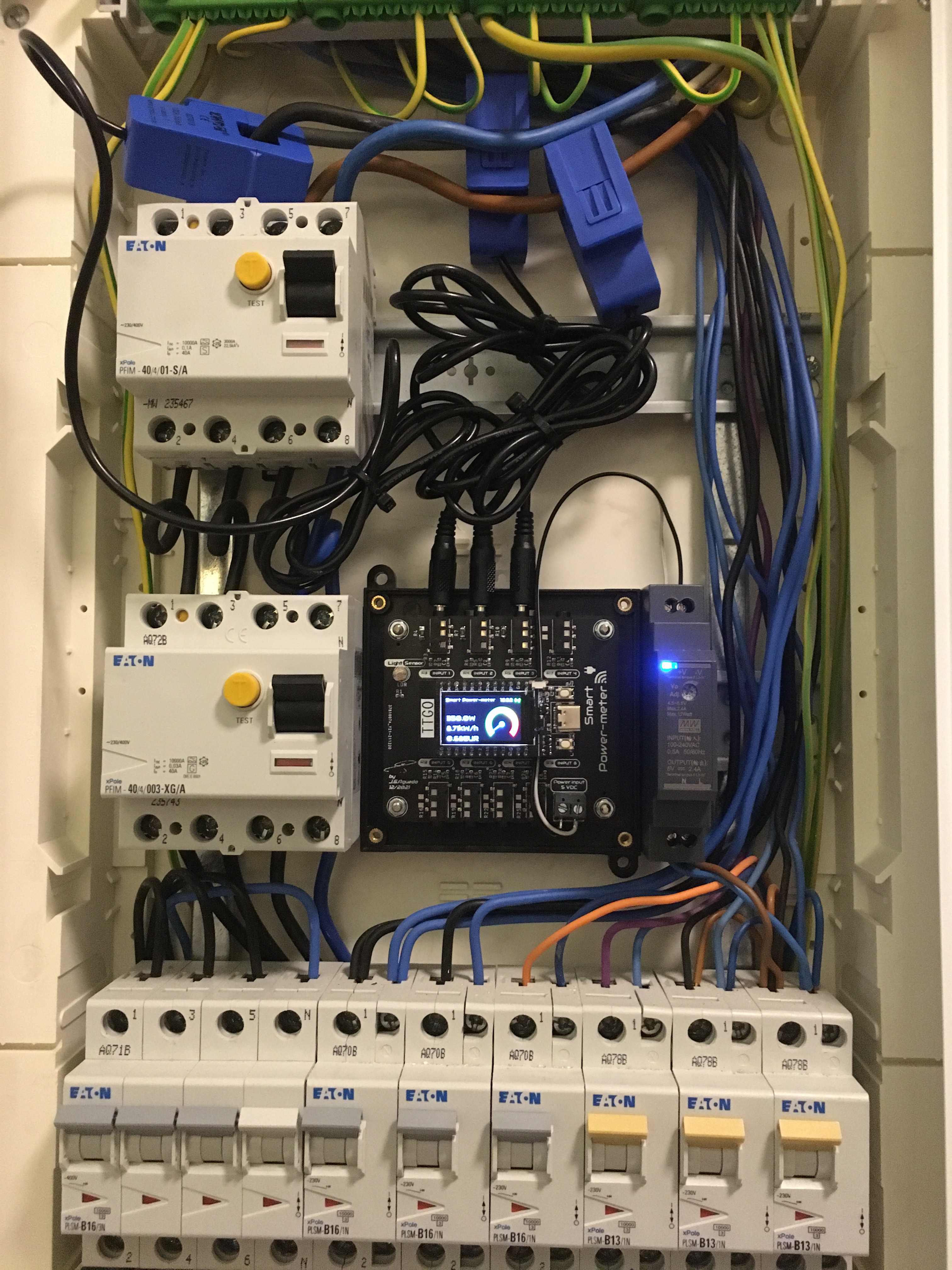
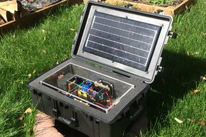
As you can see in the final setup, I choose to just measure each one on the tri-phasic lines arriving at my home just because it became quite messy to deal with too many wires and I preferred to keep it simple.
The Smart Powermeter V1R2
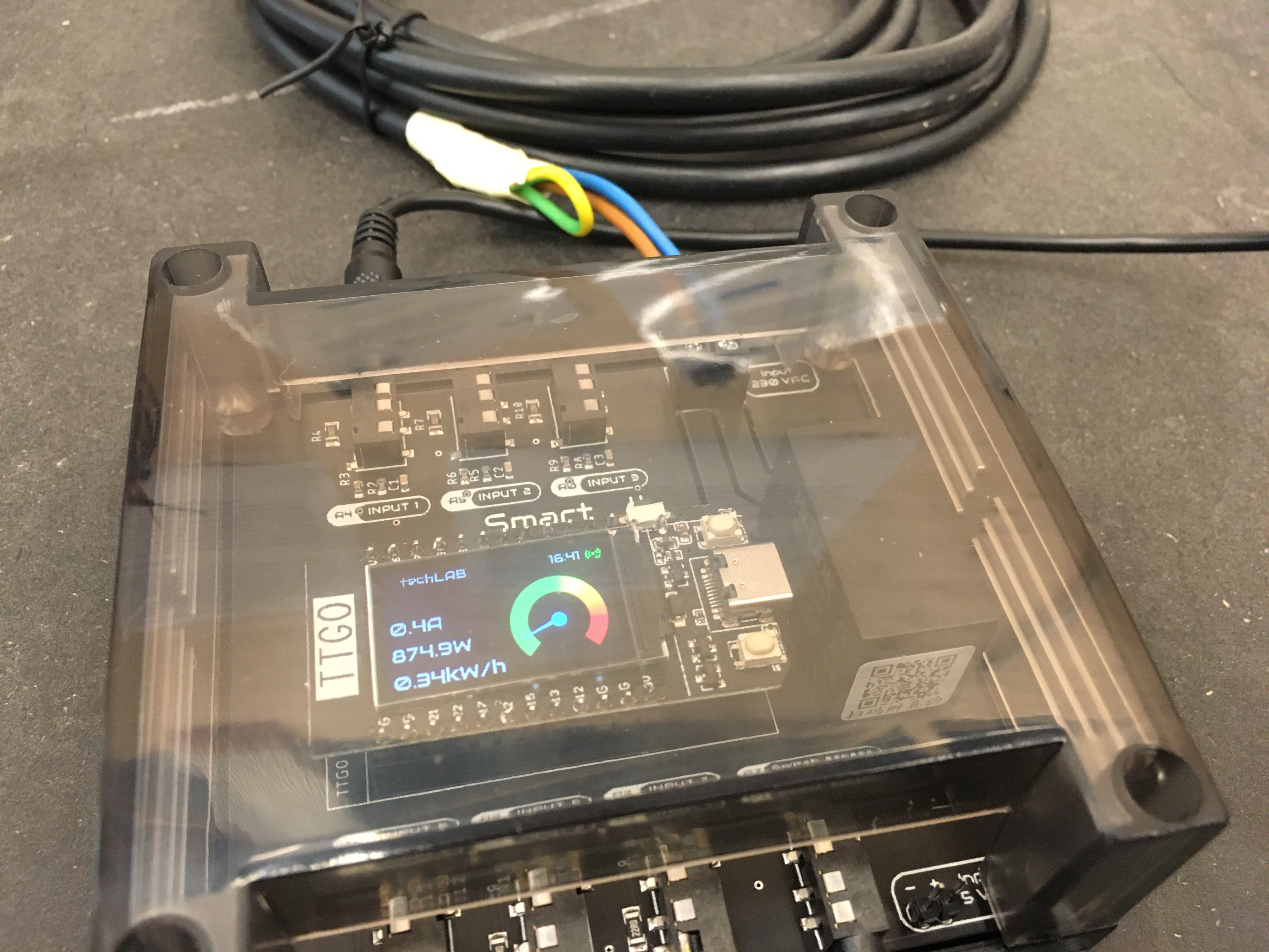
The second revision I applied to this board was really minimal, I just integrated an onboard 220VAC->5VDC power module to be able to power it without external devices and changed some silkscreen things.
This board was used as well for a divulgation talk at Vienna's Technical Museum regarding DIY Smart Powermeters.
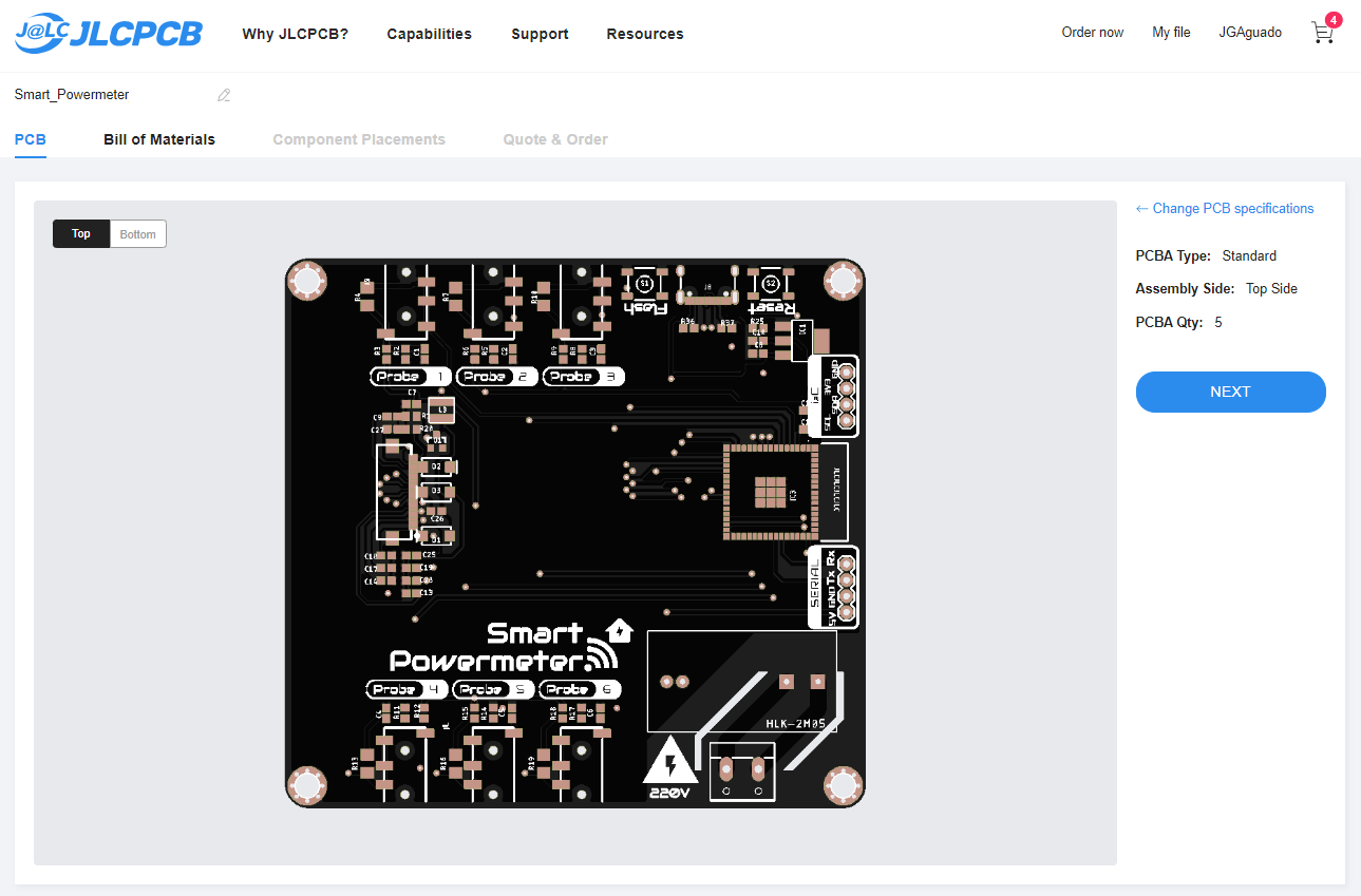
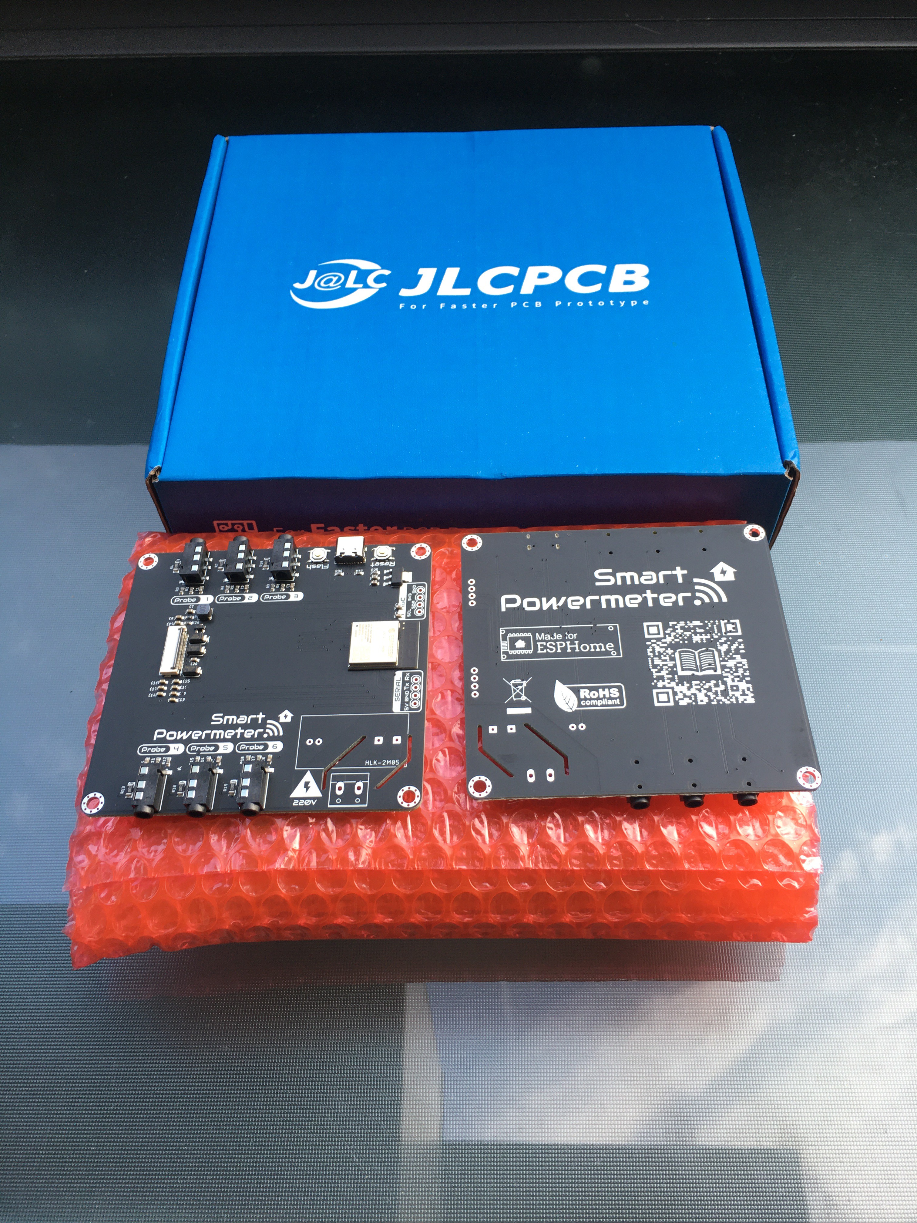
The Smart Powermeter V2R1
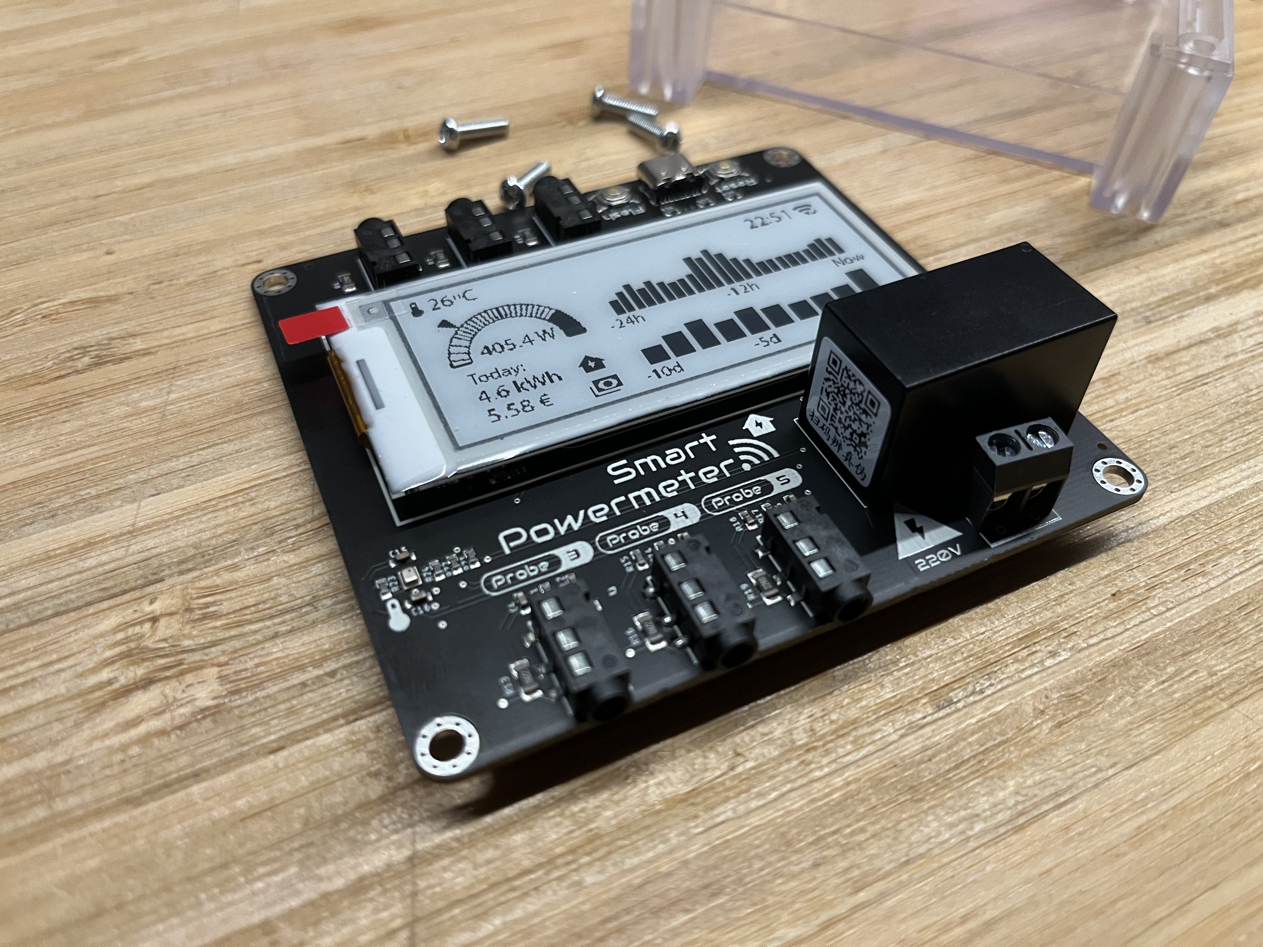
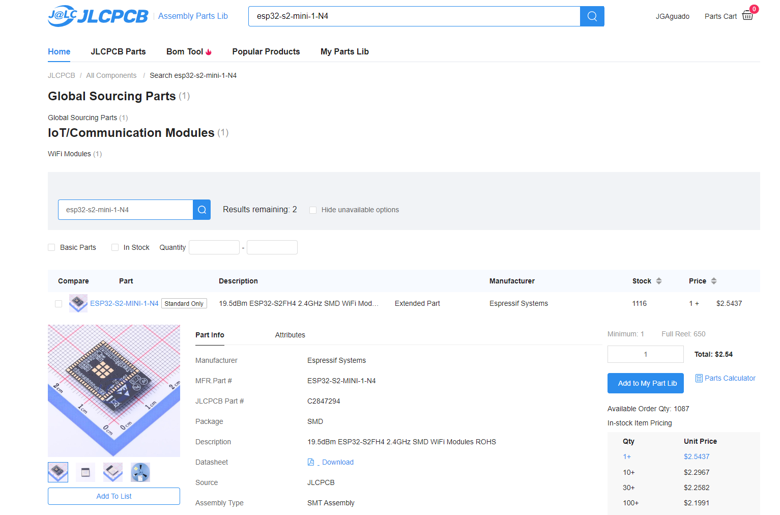
On this new development, I jumped forward embedding an ESP32-S2 module, ready to be programmed via USB-C, at the same time I provided an e-paper interface (a product of the learned lessons from the SmartPlant project).
The board size got also adapted to fit into a more transparent enclosure, the LK-PLC01. Since I was also interested in getting to know the temperatures the electric closet reached, I embedded...
Read more »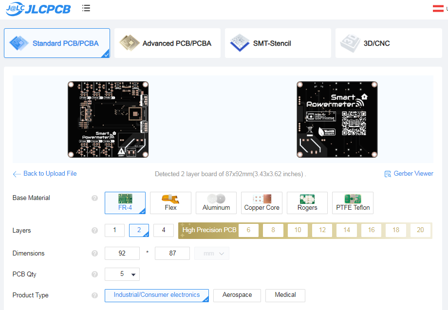


 oneohm
 c.Invent
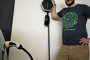
 Mastro Gippo
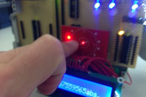
 Dave_ Z.
I got one from Elecrow and am trying to get it running. I had a lot of issue with esphome but via CLI finally got it to make be a bin file and I flashed it using flash_download_tool_3.9.6. No matter what I do the device just seems dead. No wifi, nothing on the screen, no lights, nothing. Only reason I don't think it's totally dead is that I can put it in flash mode and flash it. I connect with serial and nothing. I'm no stranger to microcontrollers or esp32's, I wrote FAT32 and cell modem firmware. Any help? Thanks!