 Ray Burne
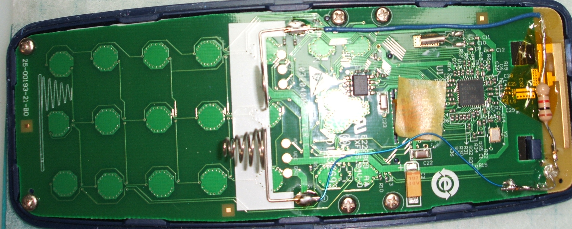
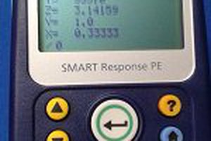
Sometimes there is no good reason to pursue a project other than it seems like fun; even when completed, it may be difficult to describe the intended use. This is one of those projects: a surplus Smart Response PE candy-bar style device with a TI CC2533 uC, a LCD, and a numeric keypad and a few control keys.
This comes on the heels of my previous Smart Response PE project which created a RPN calculator. This project uses the same foundational software environment and similar code structure. Written in C89'ish style, the core hardware libraries by Github user serisman allows for an arduino-like programming experience; excepting the background preprocessing magic performed by the ArduinoIDE, for example, automatic prototyping of functions.
Implementation
Only the 0-9 numeric keys, the ENTER key, and the Home key are utilized. Pressing 0 - 9 will activate (link) the stopwatch timer to the internal millisecond clock. The timer will be located on the LCD in the following order:
( 1 ) ( 2 )
( 3 ) ( 4 )
( 5 ) ( 6 )
( 7 ) ( 8 )
( 9 ) ( 0 )
and each will be in the format: MM:SS.xxx where the behind-the-scenes HH: is masked due to minimum LCD real estate.
The ENTER key:
will pause the LCD display (not the timer counting) until pressed a second time to resume the LCD display.
The HOME key:

Does a reset on all timers, clear the LCD screen, and essentially does a soft-reset for new usage.
Notes and Considerations
Some (quick) empherical testing was completed during the software writing to determine how to minimize delay in linking the immediate keypress to the software variables used for the 10 timers; that is, an emperically constructed numeric constant was implemented depending on where the key ( 0 - 9) was implemented in the keyboard scan matrix and within the "switch/case" statements. These constants are approximately 1mS different from key-to-key and in actuality use have no apparent bearing on the common usage of the device. Of course, until implemented, the impact was unknown and in hindsight was essentially a waste of time!


 rahmanshaber
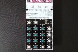
 Arduino Enigma
 Nguyen Vincent