 Jamie Matthews
Why Not Just Use Batteries?
There are so many reasons supercapacitors are much better suited for low power applications like this, most modern 18650 batteries have a typical cycle life of 300 - 500 (charge, discharge cycles) whereas supercapacitors have 100000 to a million life cycles!
That means the performance of the capacitor will not degrade over the products lifespan like li-ion and in turn we get a product with a MUCH longer lifespan.
Then there is the quick charging, if your power source is capable of high currents we can literally charge a product fully in seconds.
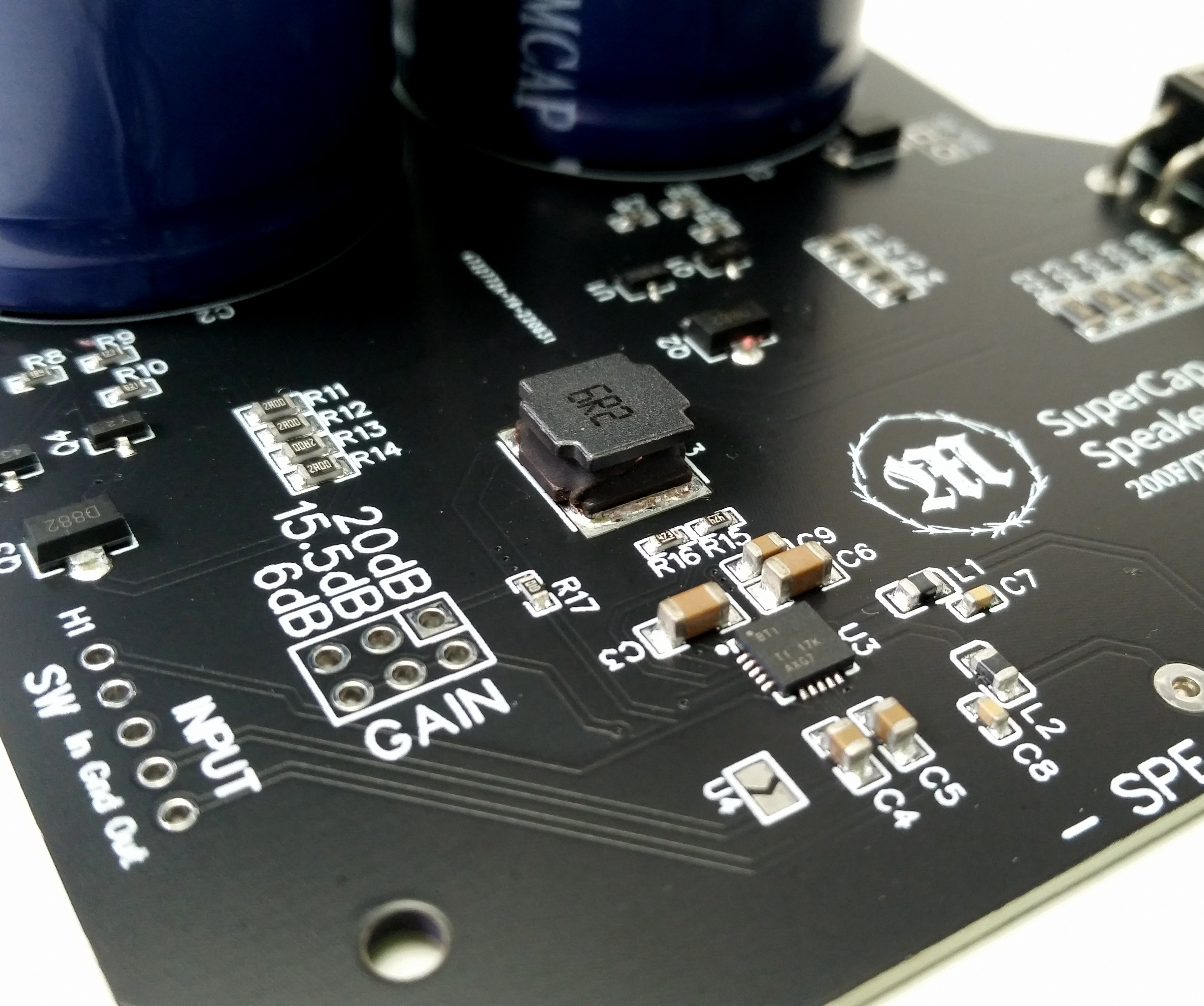
The Electronics:
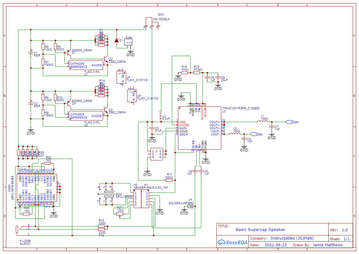
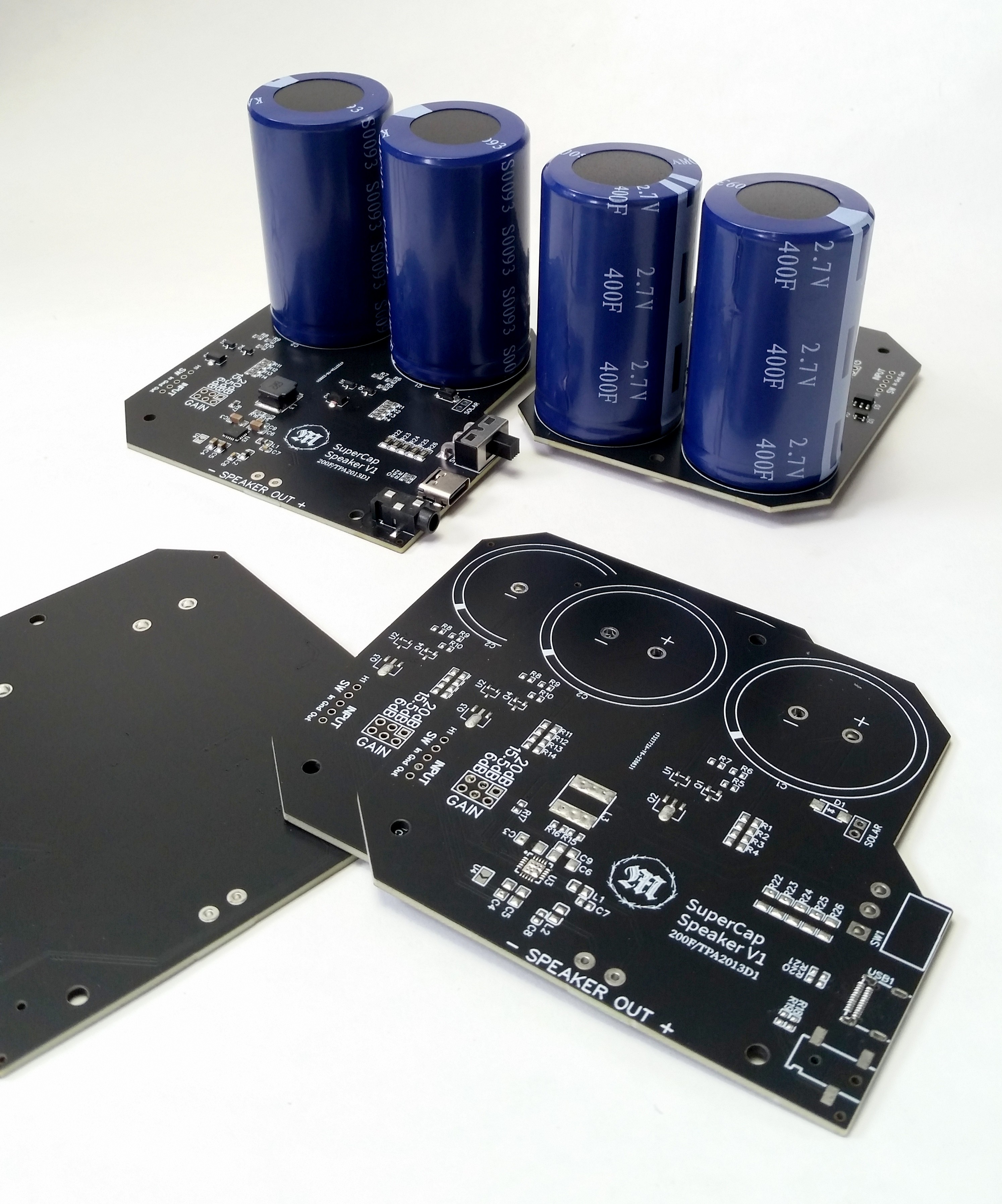
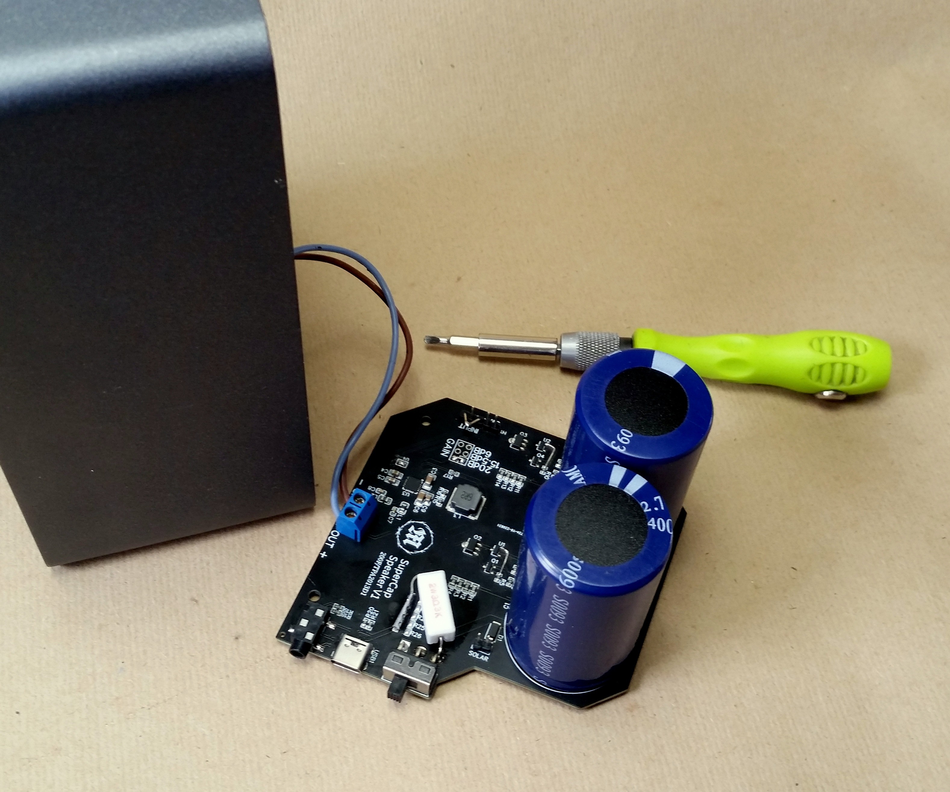
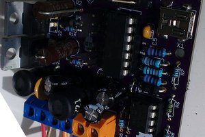
The circuit is designed around two 400 Farad supercapacitors that are in series giving us a working voltage of 5.4 volts and 200 Farad capacitance when fully charged. To protect the supercapacitors from overcharging as well as to keep the two balanced I added a protection circuit using the old trusted TL431 IC to each capacitor in order to keep each below the 2.7V maximum rating.
Unfortunately unlike lithium batteries with supercapacitors the voltage drop is linear as it depletes, to counter this we need a boost converter to keep the output voltage stable otherwise the output of the audio amplifier will quickly drop and stop working once it reaches it's minimum rated voltage.
Luckily we get amazing chips like the TPA2013D1 that has a built in boost converter with an operating voltage of 1.8V to 5.5V and also the boost circuit gets disengaged when our supercapacitors are fully charged making even more efficient.
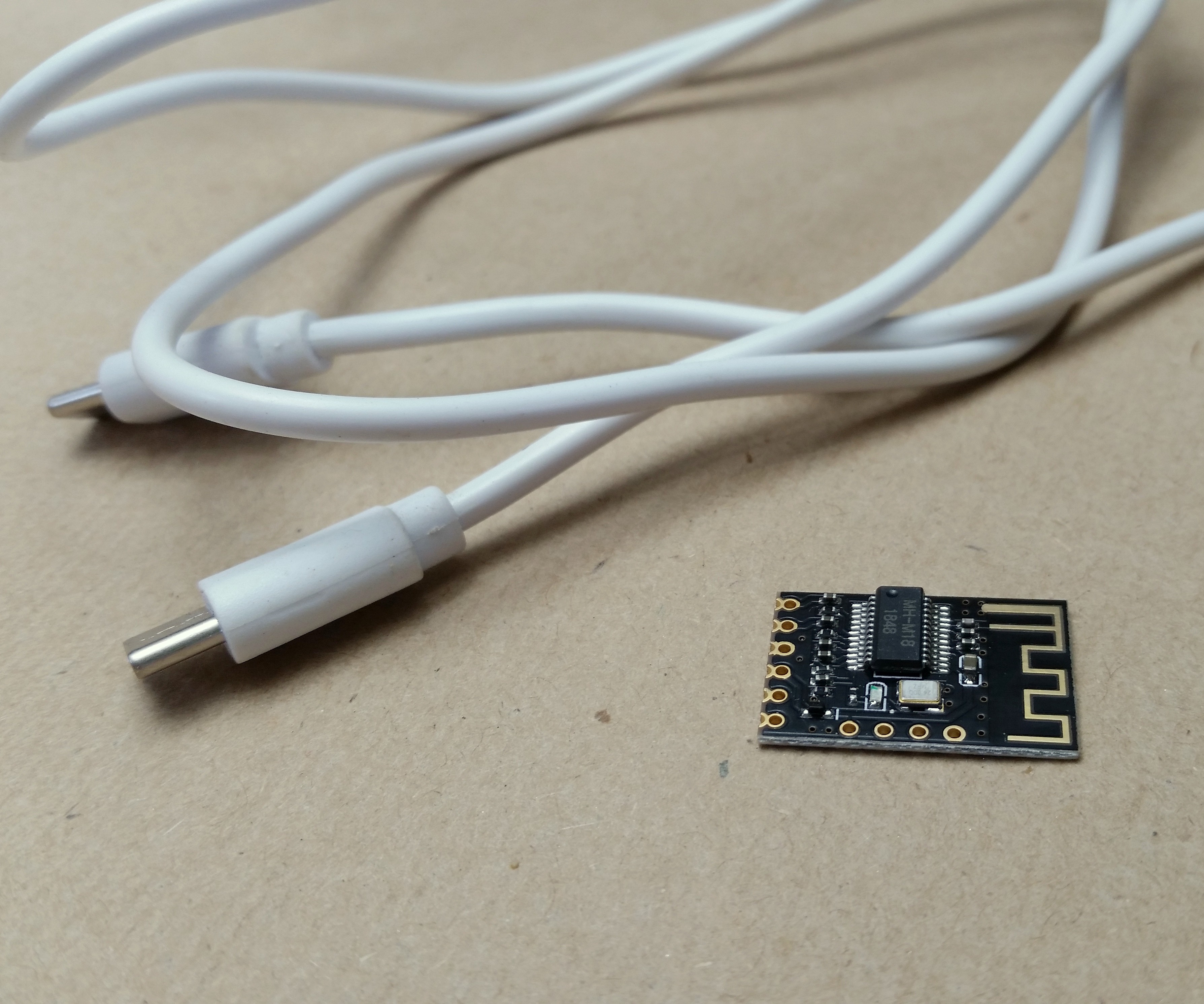
I added a USB-C for charging from an adaptor if you are in a hurry any the capacitors are depleted.
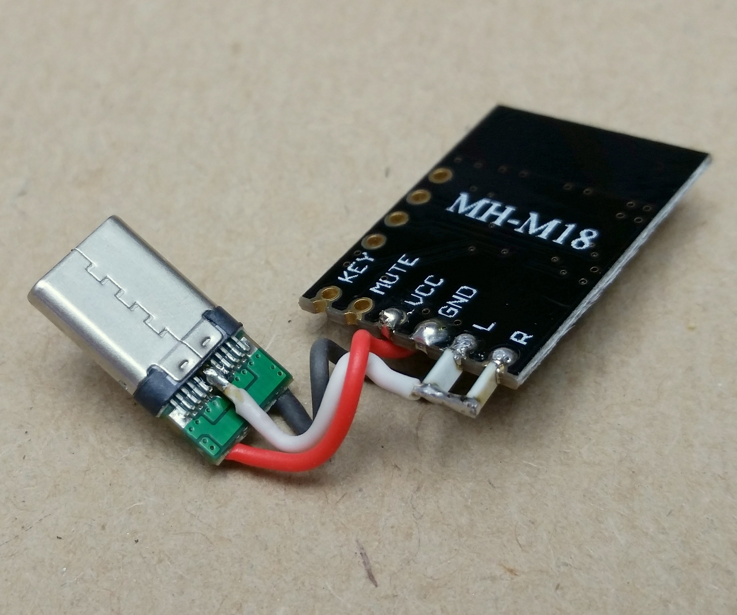
The USB-C is also wired for analogue audio input which enables audio to be played over the USB cable when plugged into the USB-C port on your laptop/desktop while also charging the capacitors.
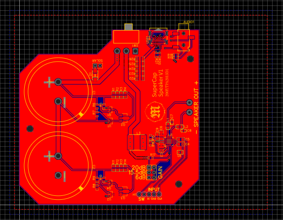
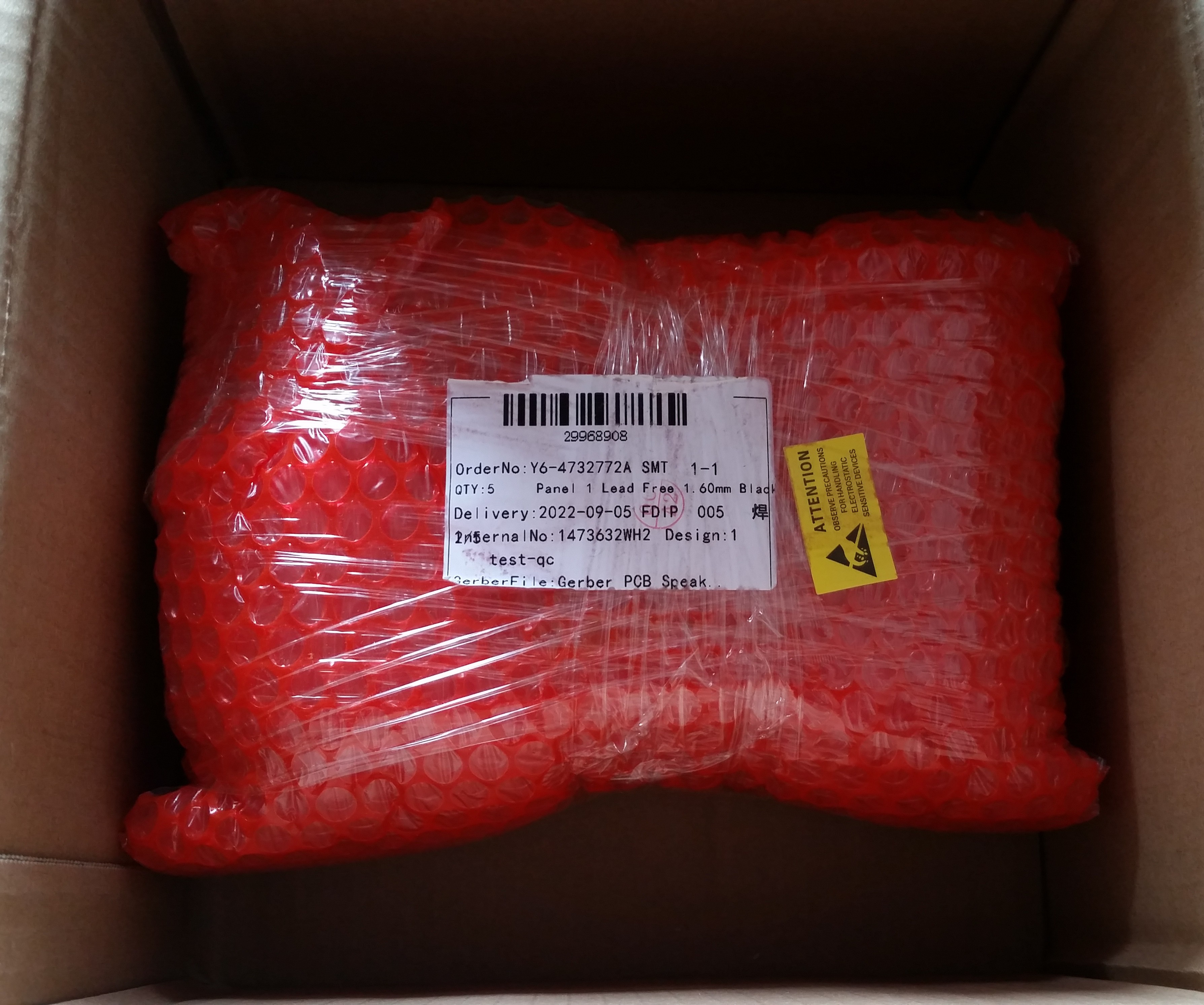
I ordered SMD assembled PCB's from JLCPCB to test the concept and received the finished boards within two weeks.
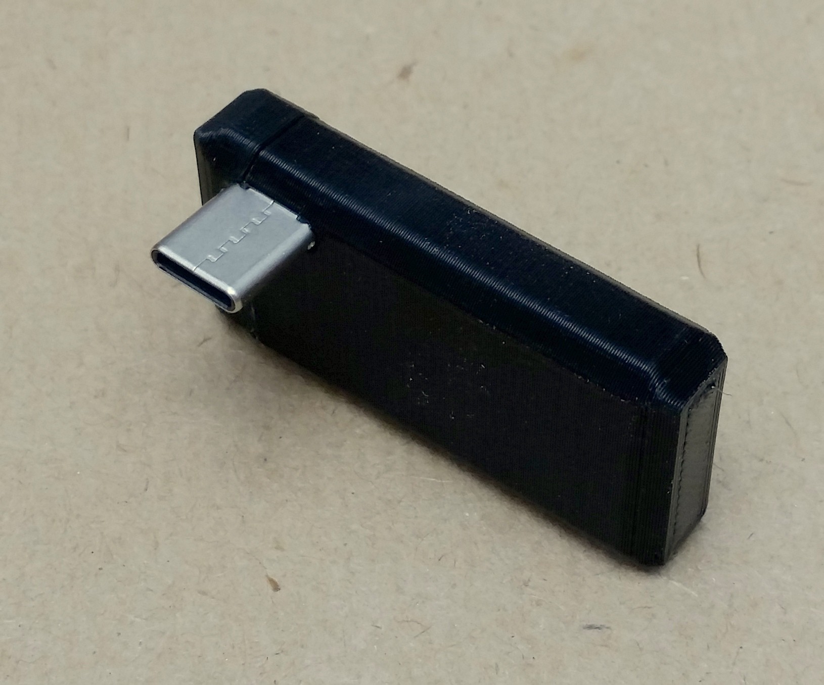
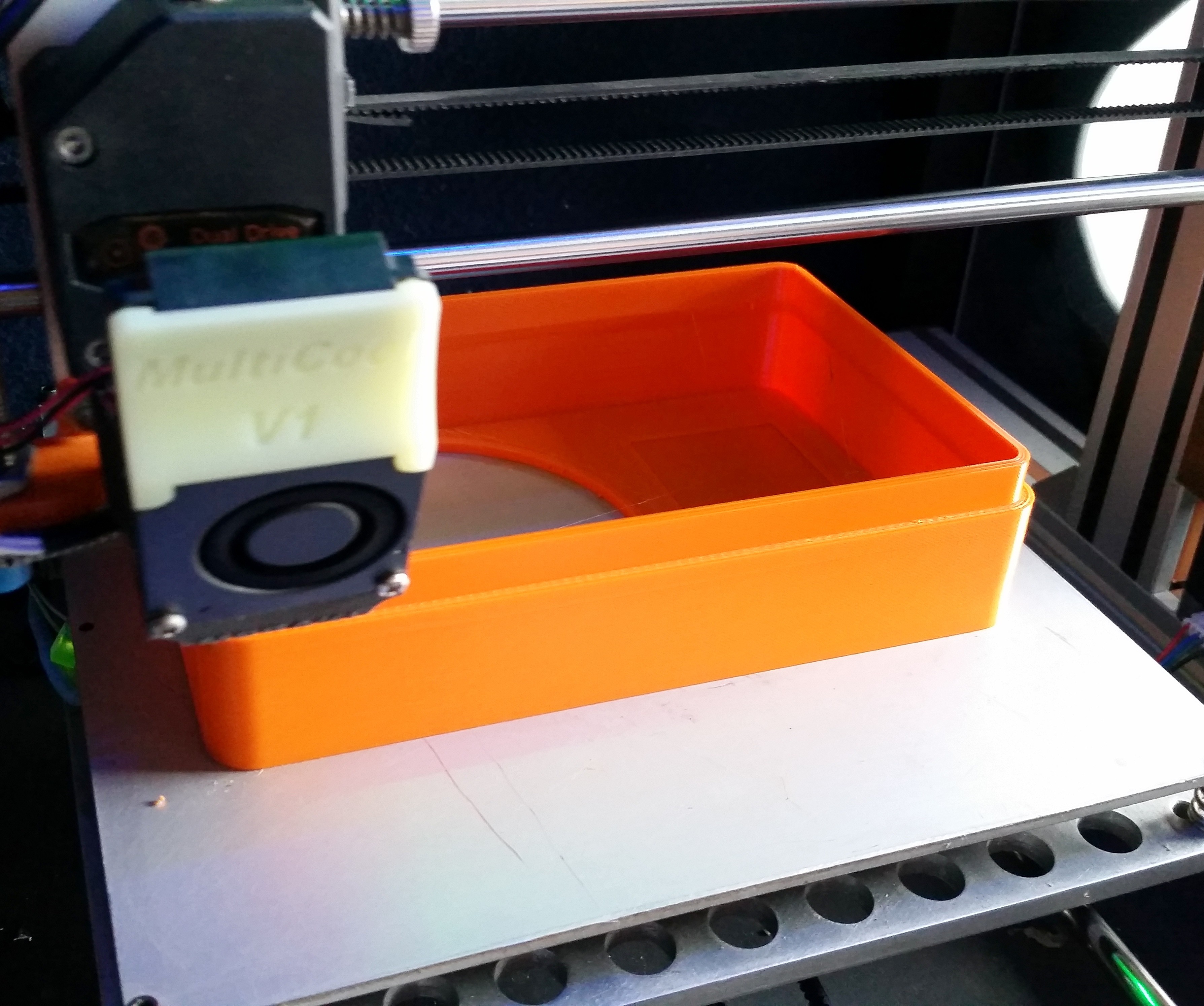
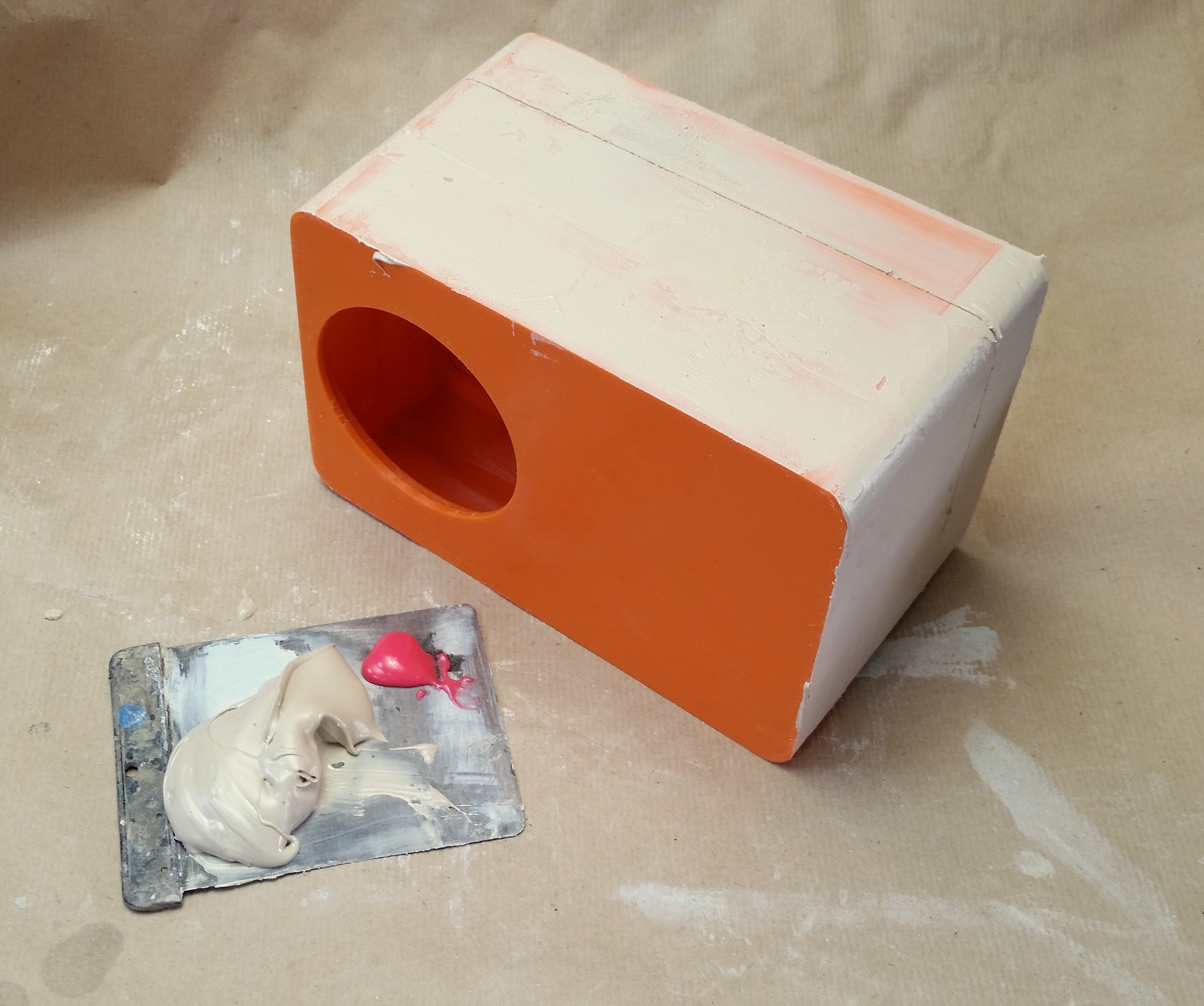
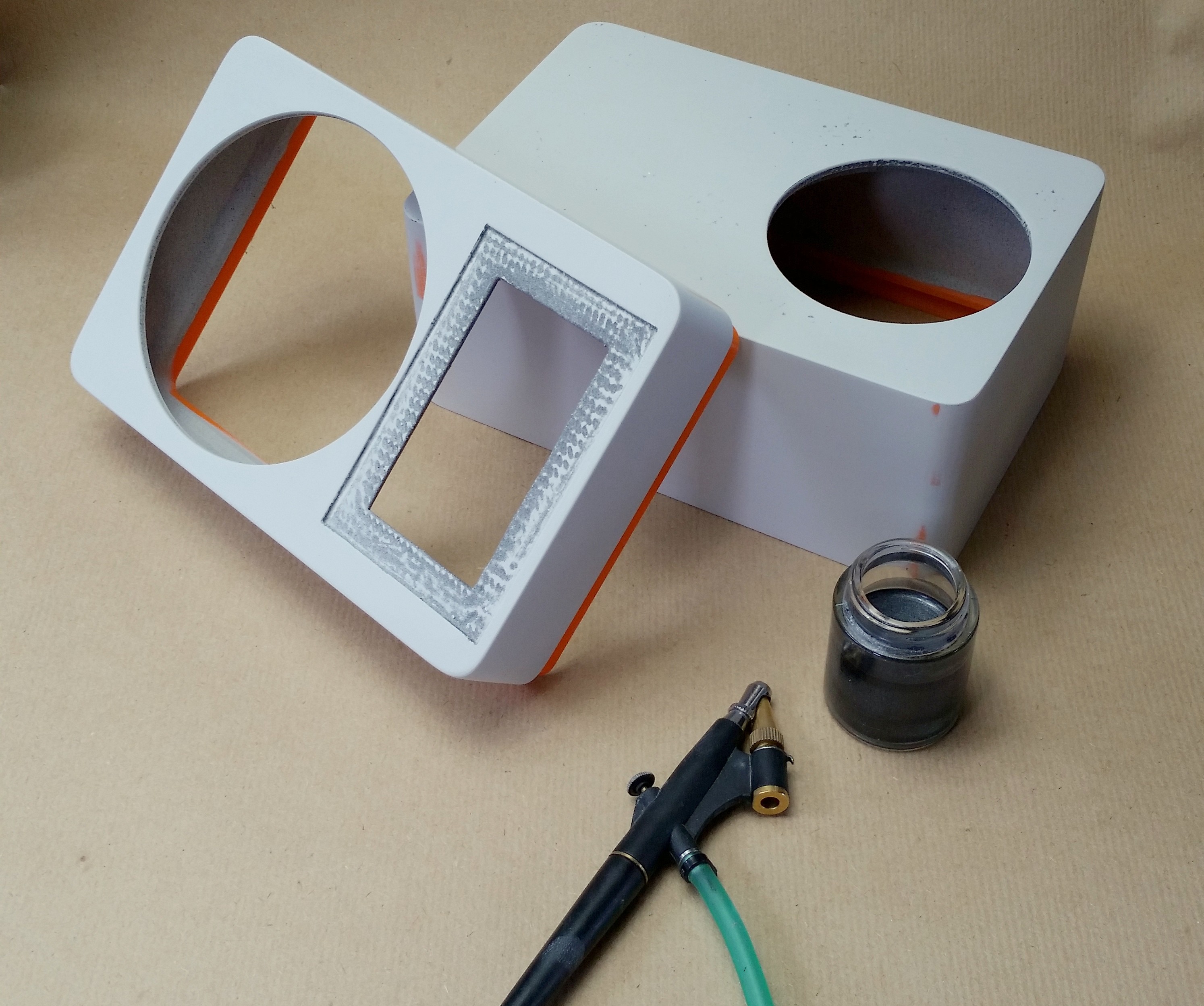
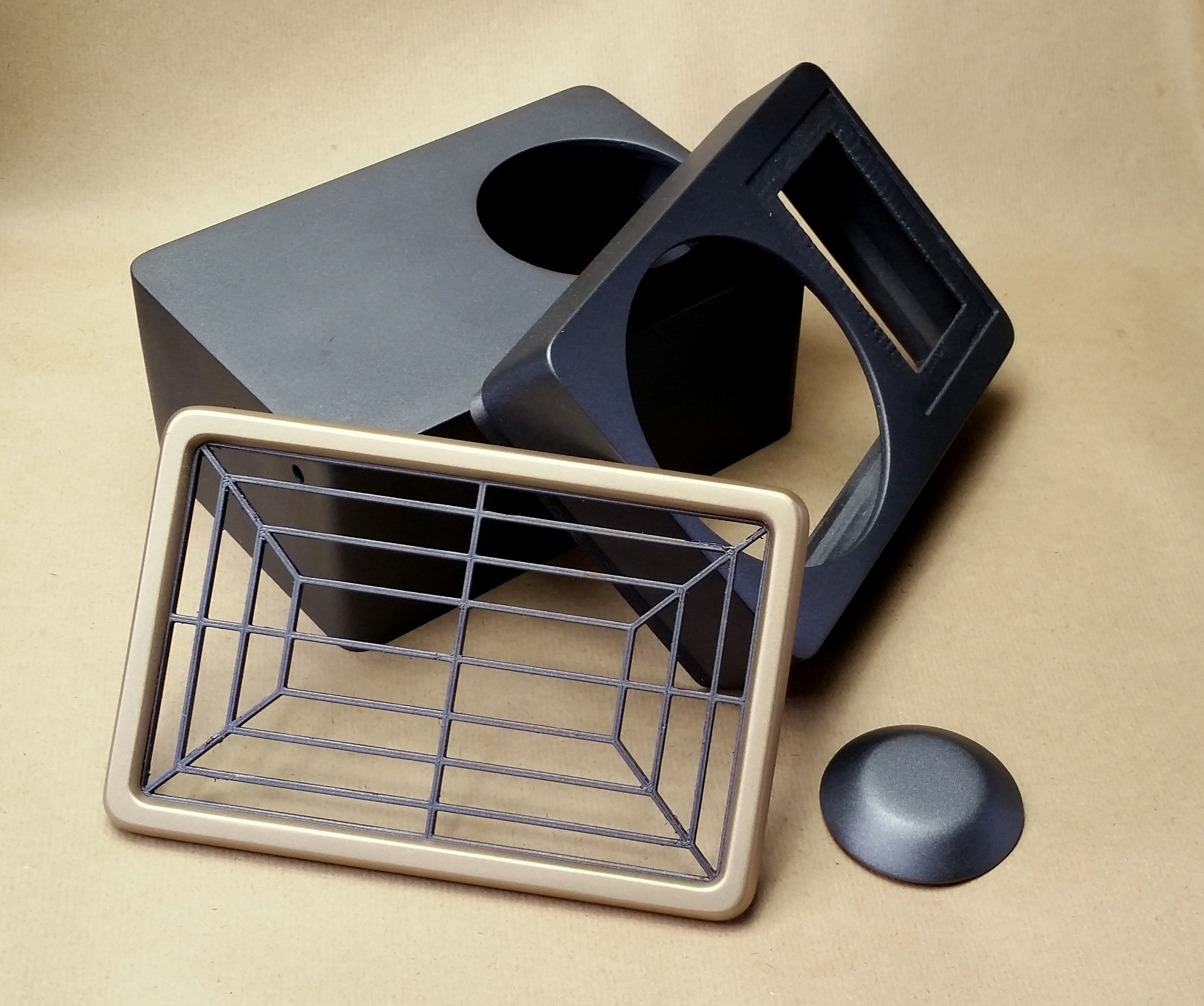
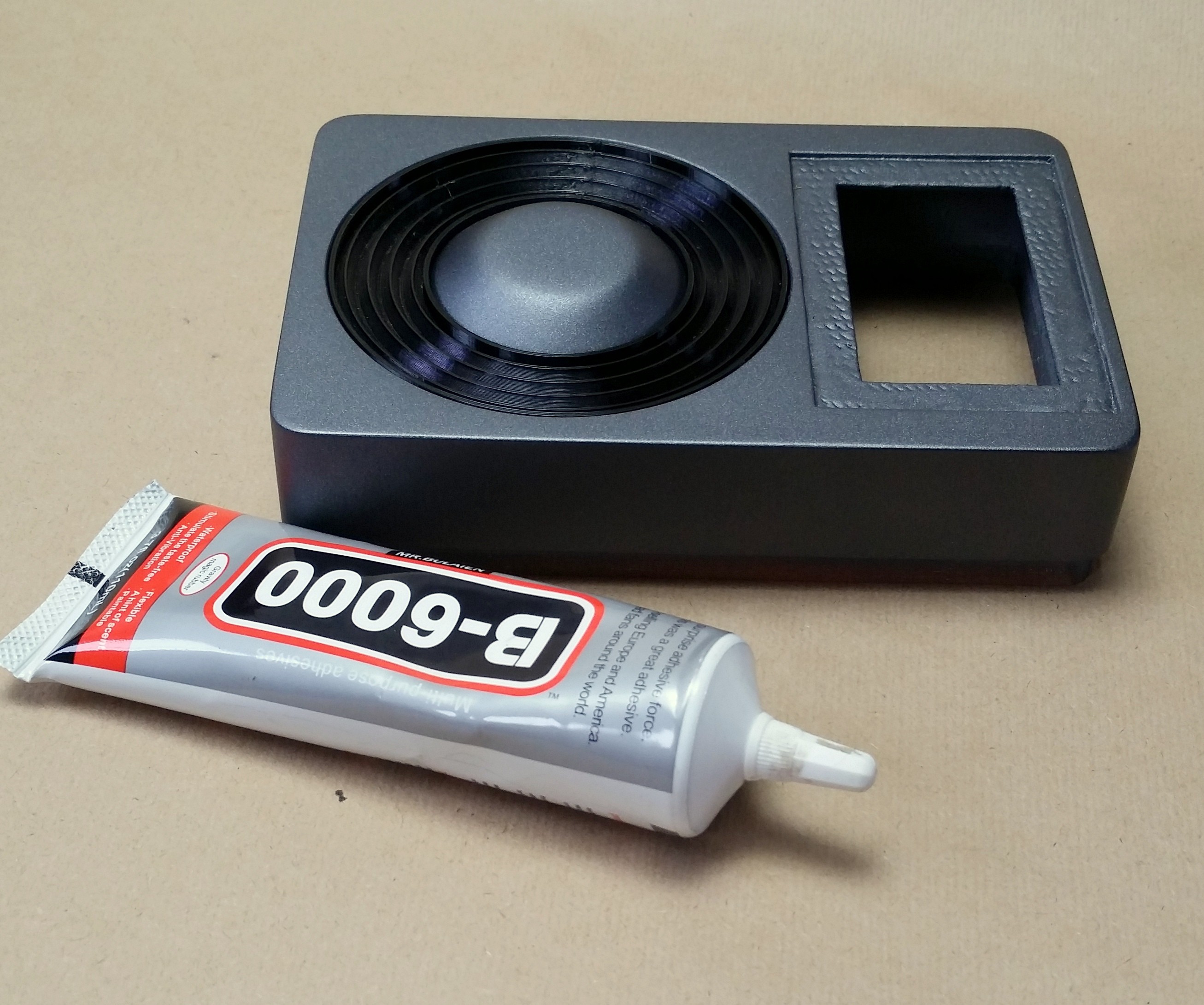
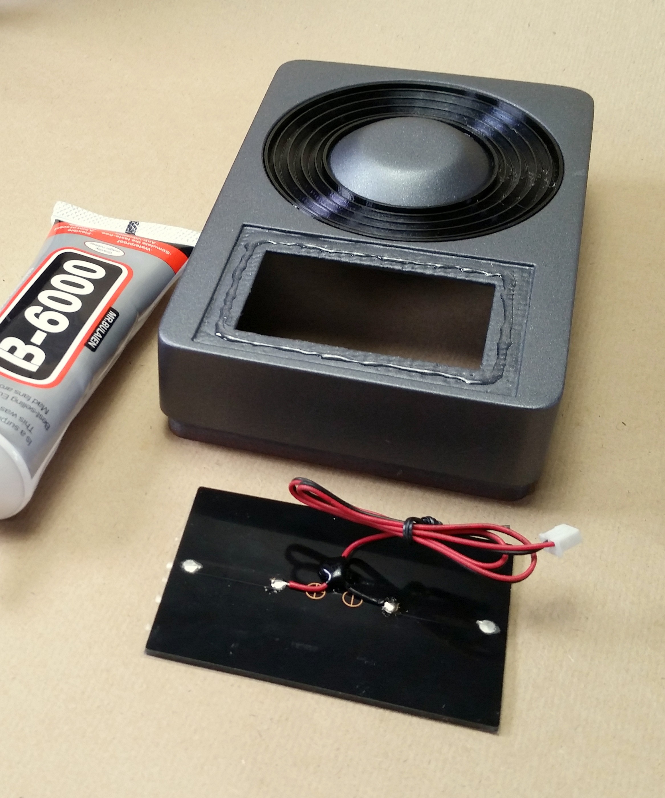
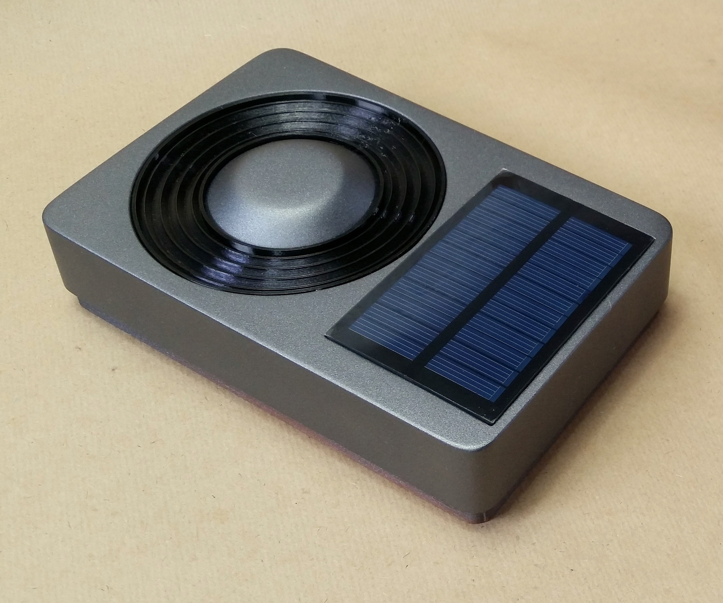
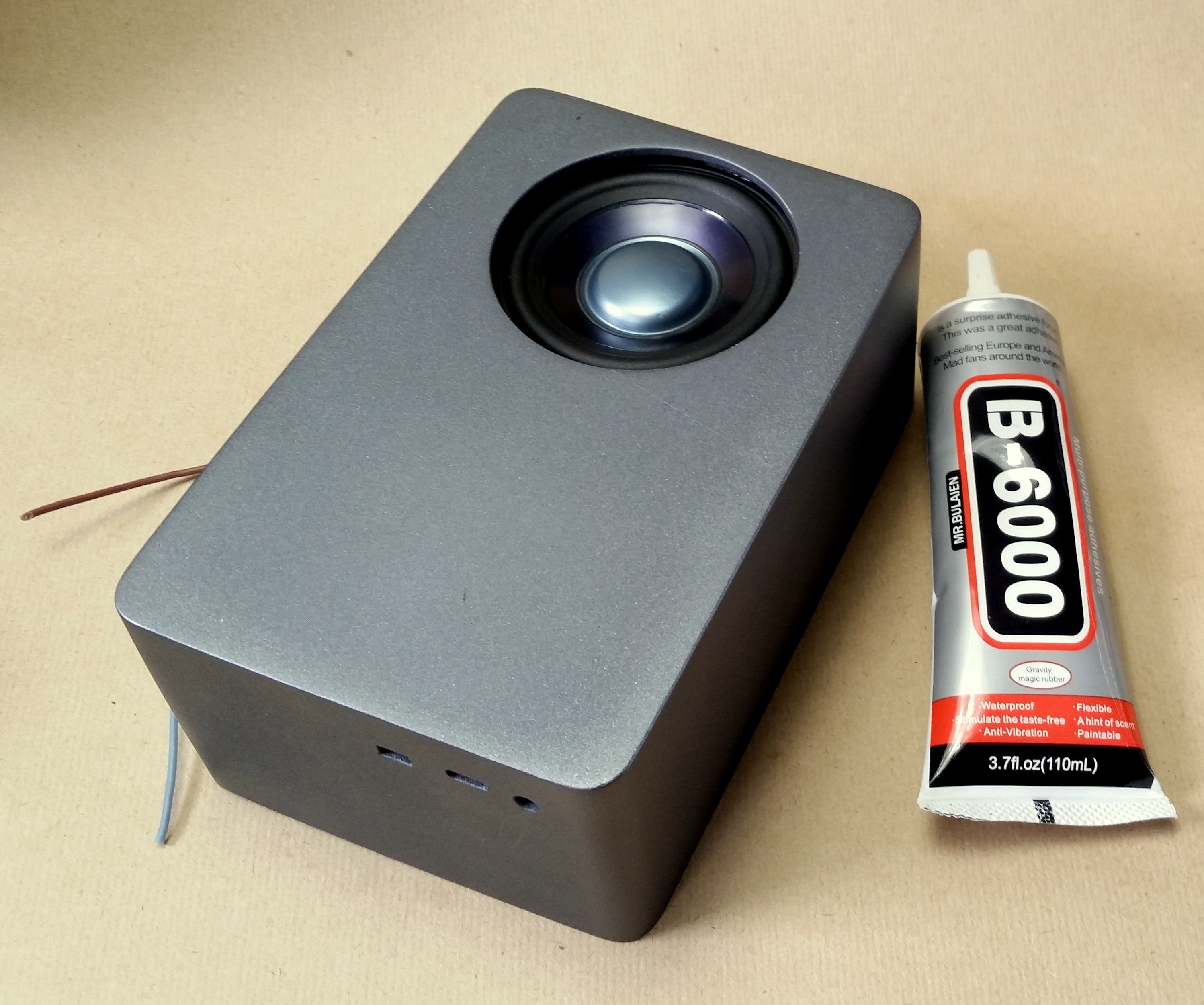
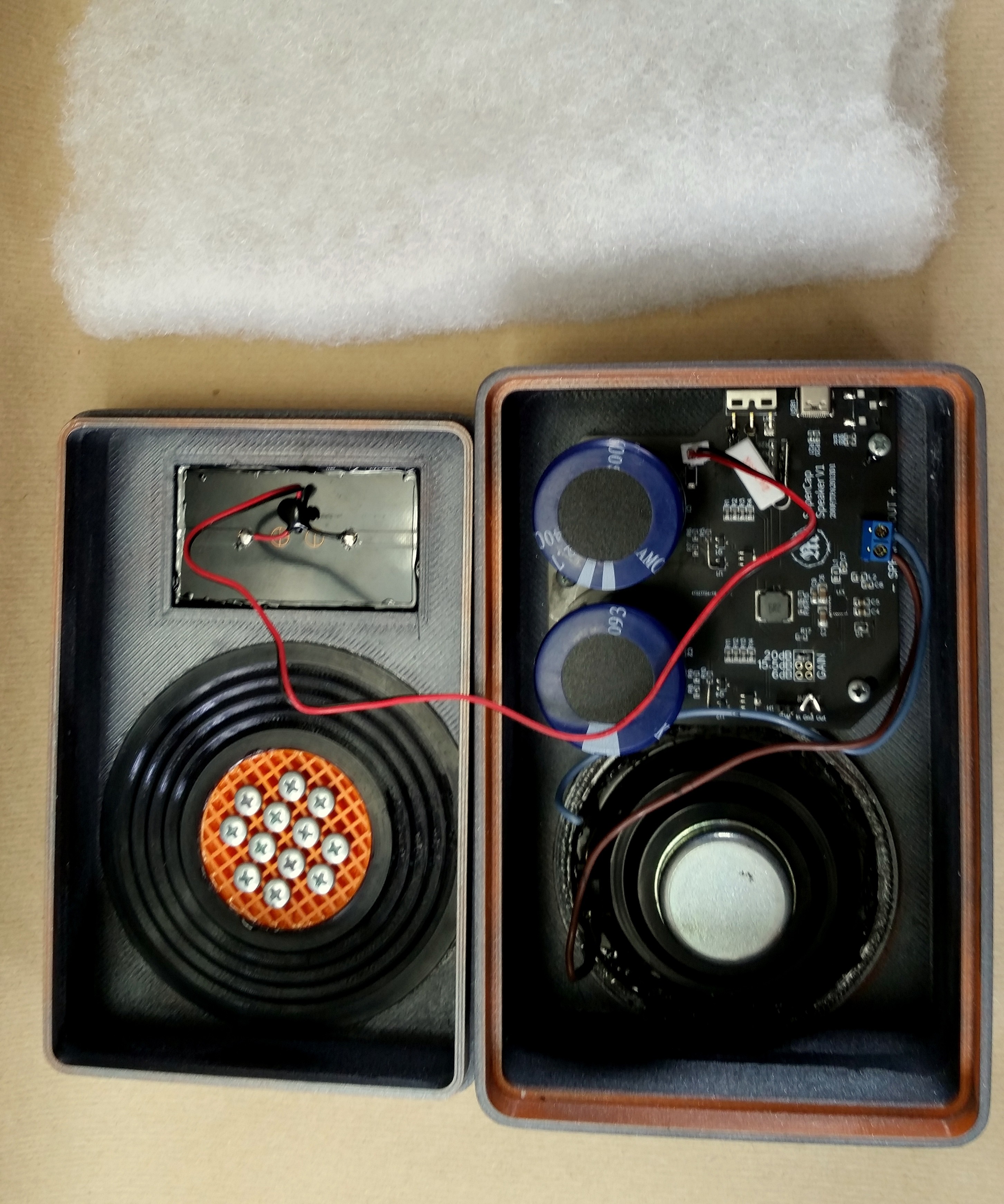
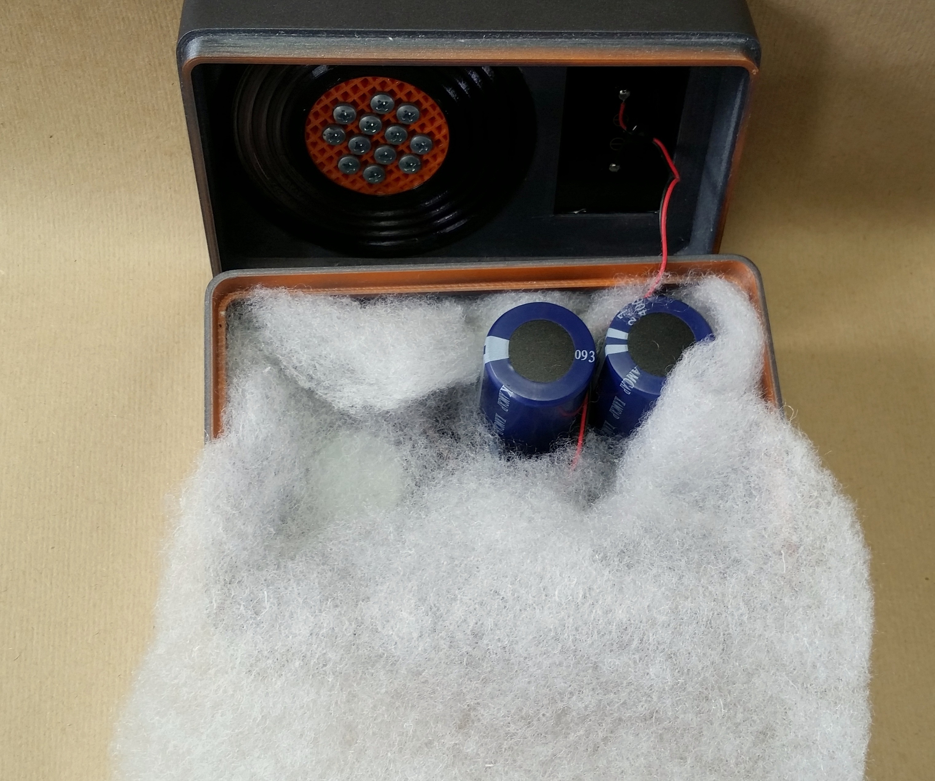
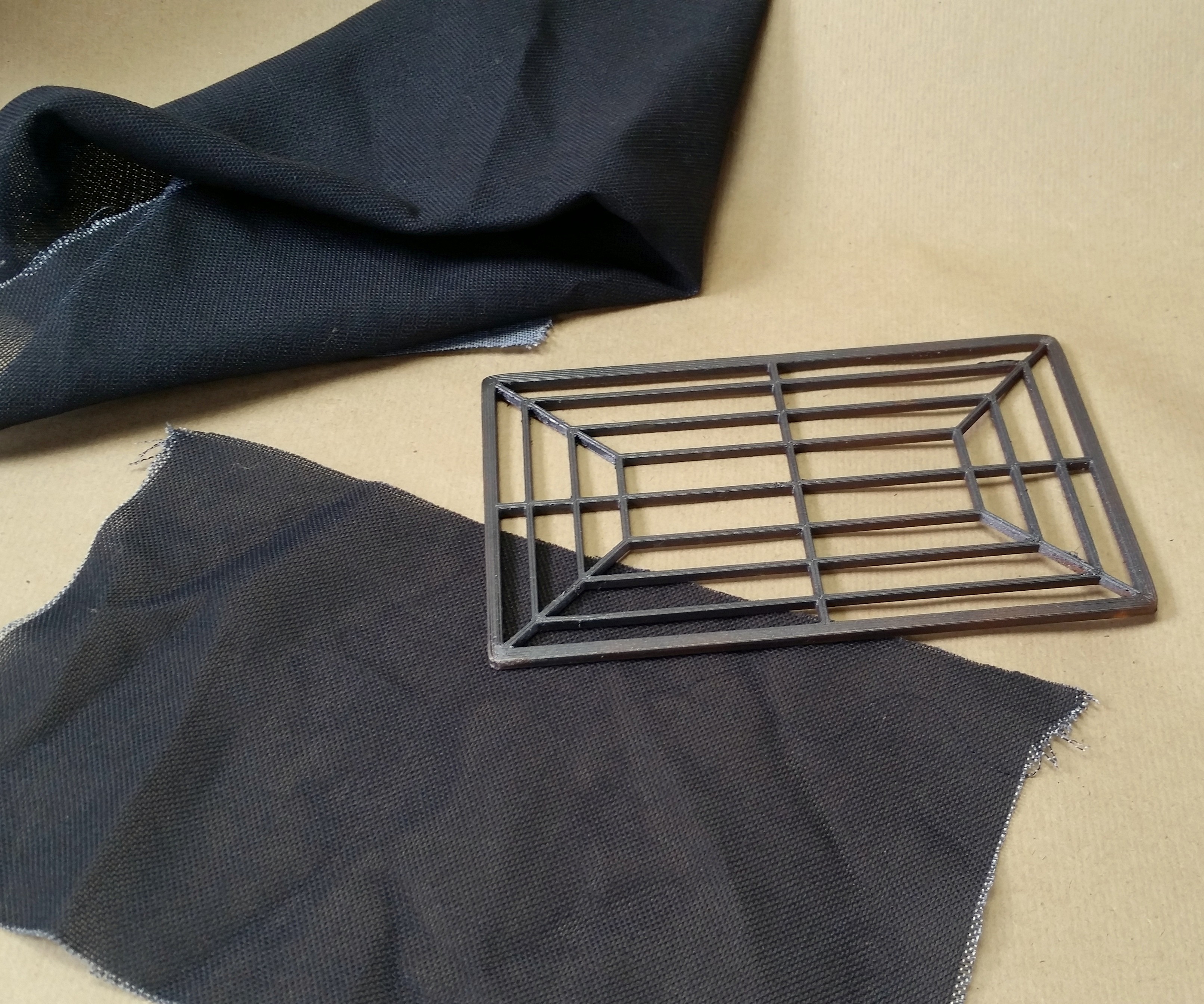
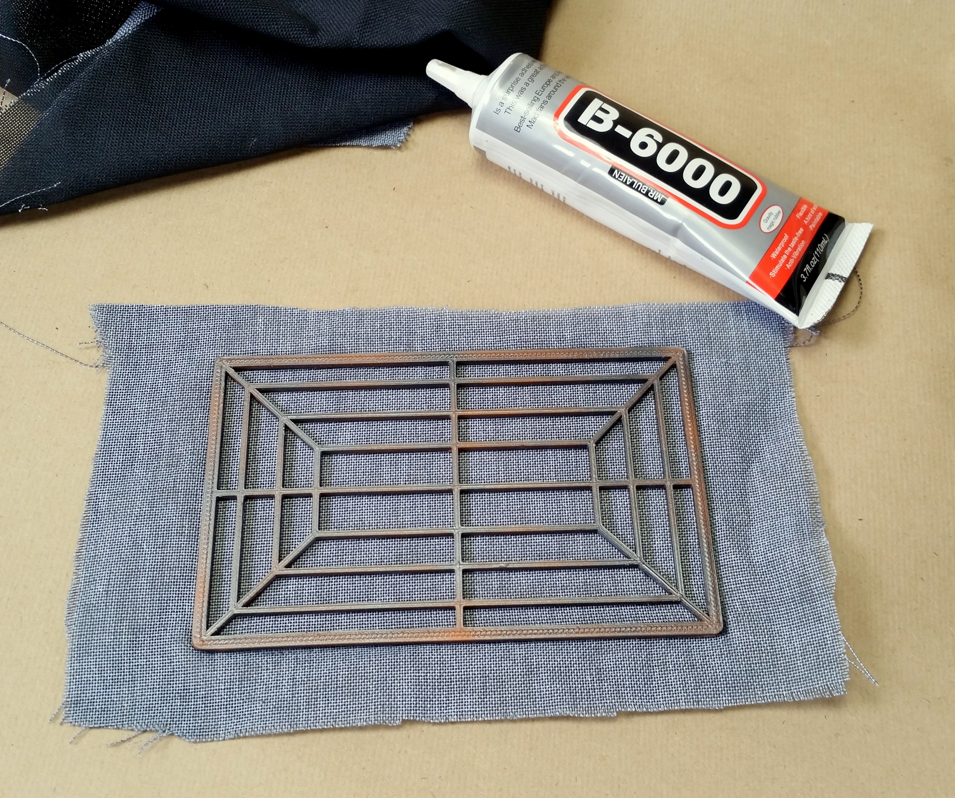
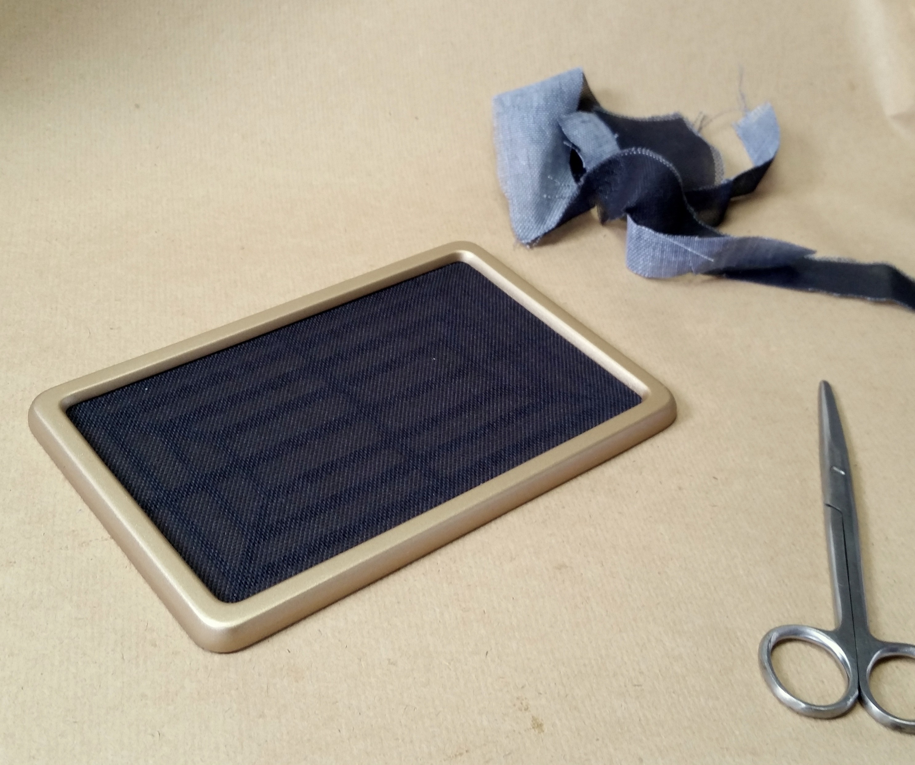
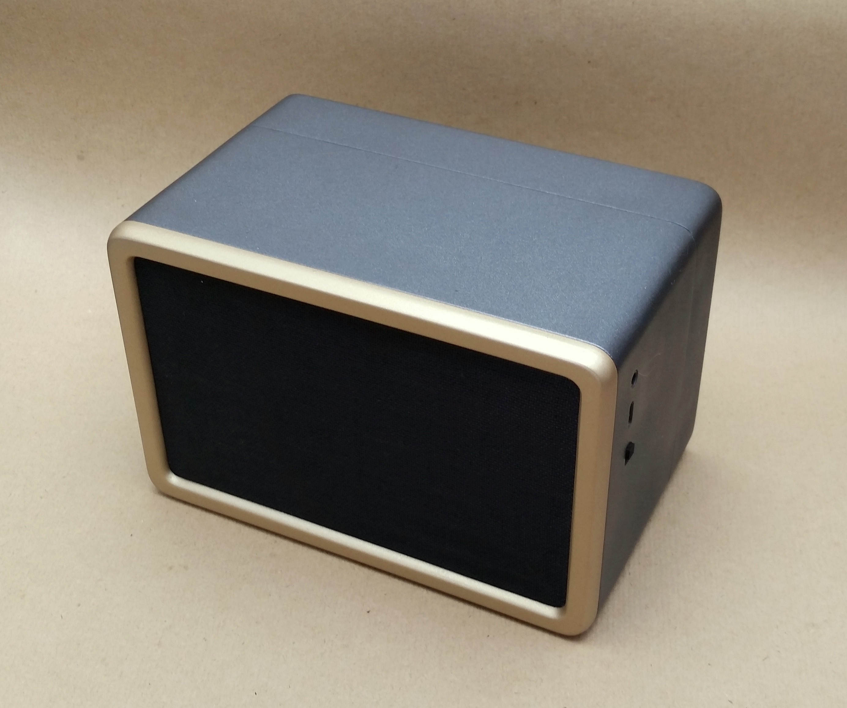
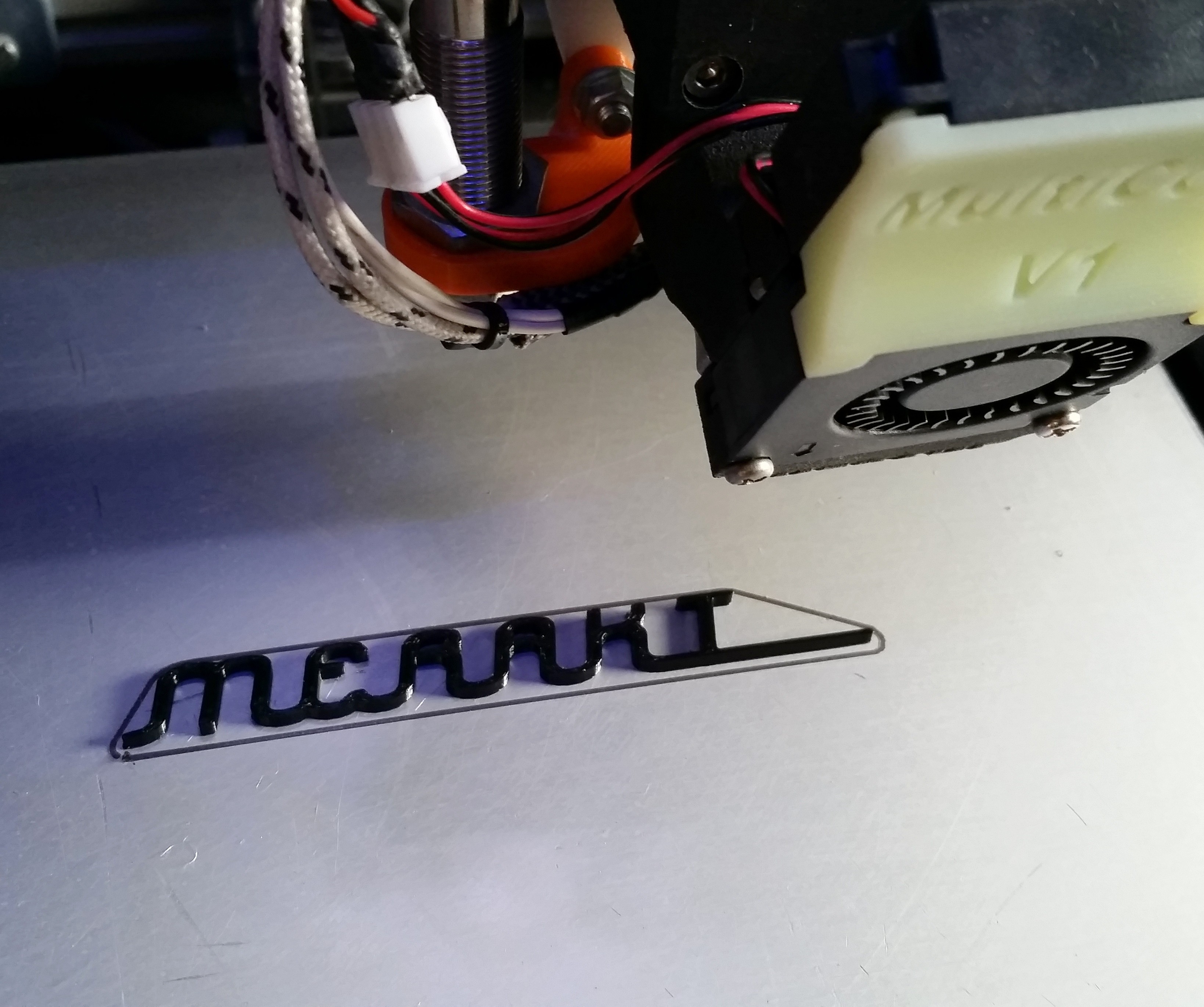
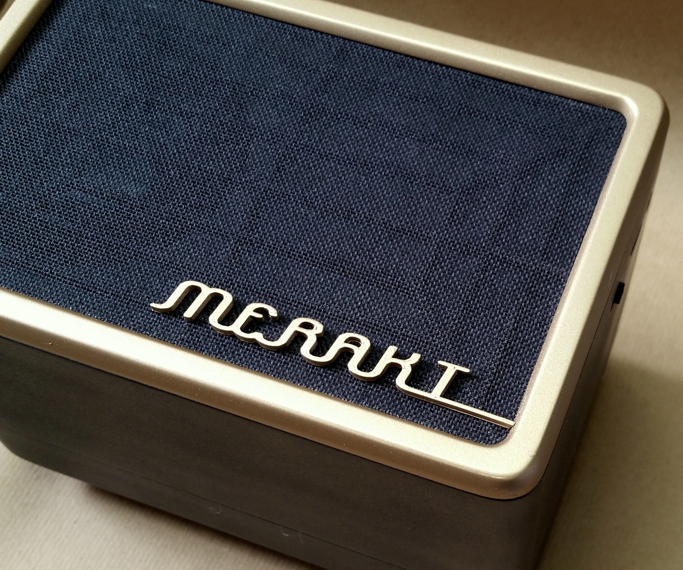
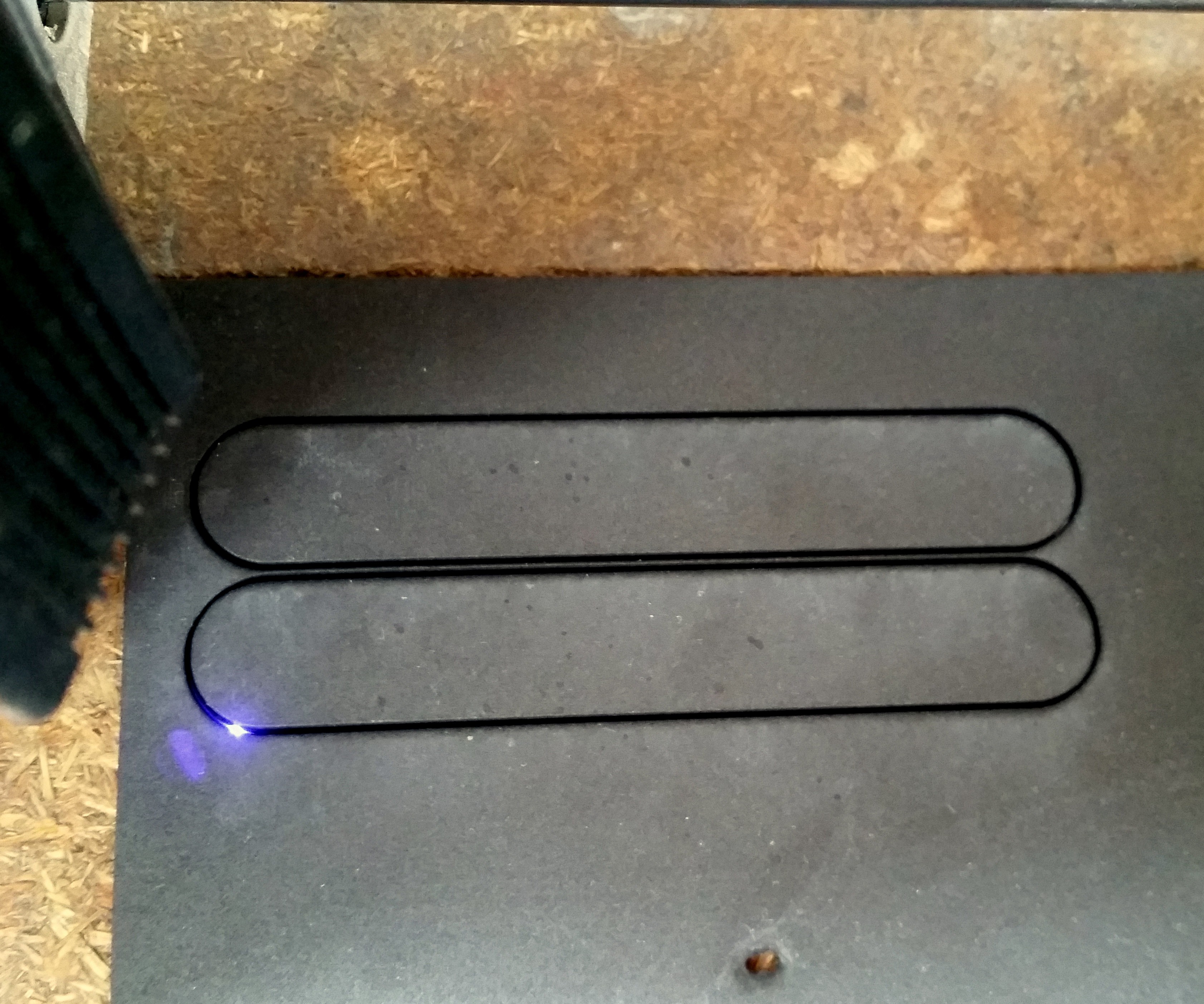
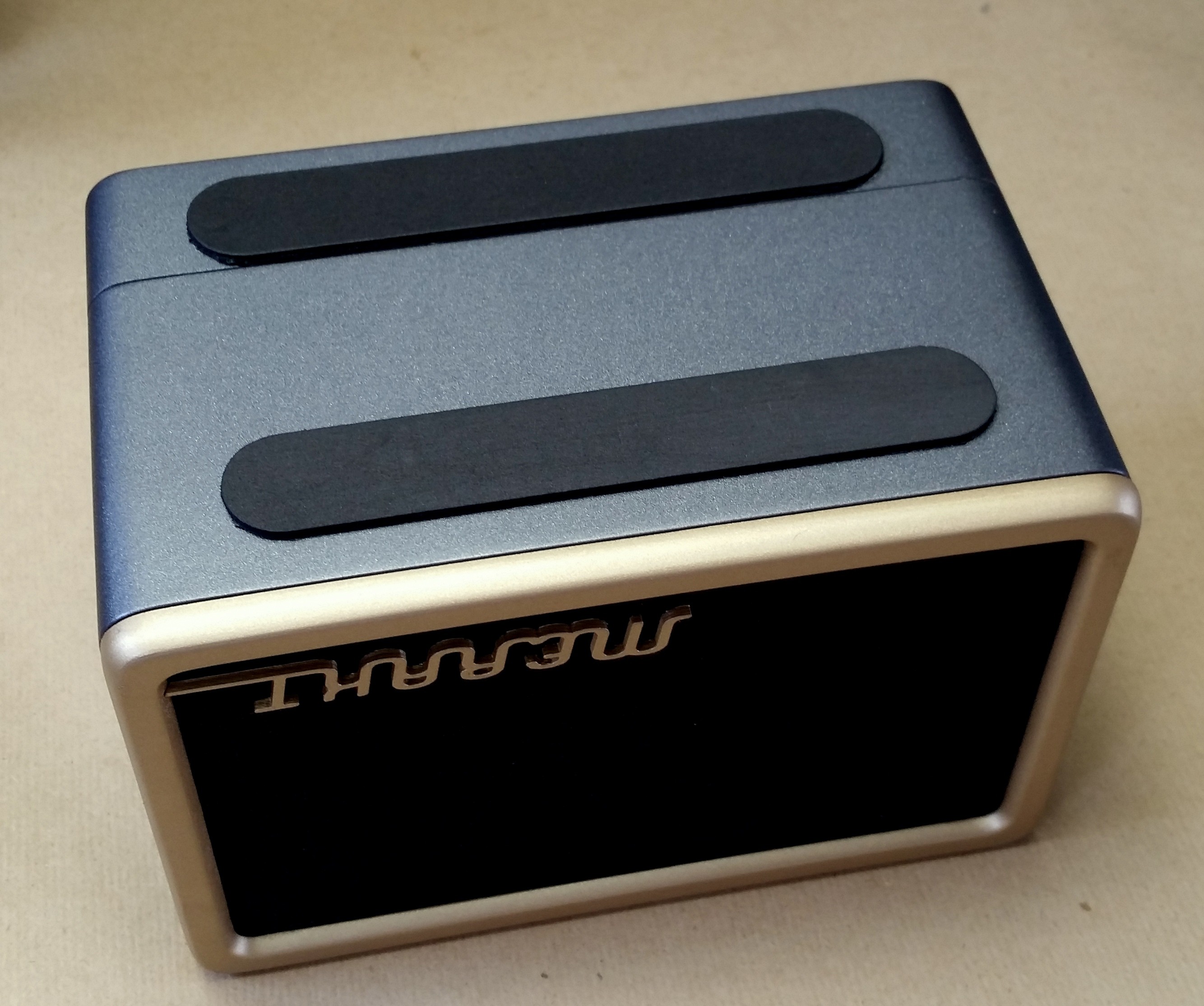
The Enclosure:
Step by step building instructions included.

 Gorky
Gorky
 Dylan Bleier
 SAYANTAN PAL
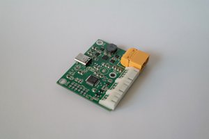
 Alex Klimaj