0%
0%
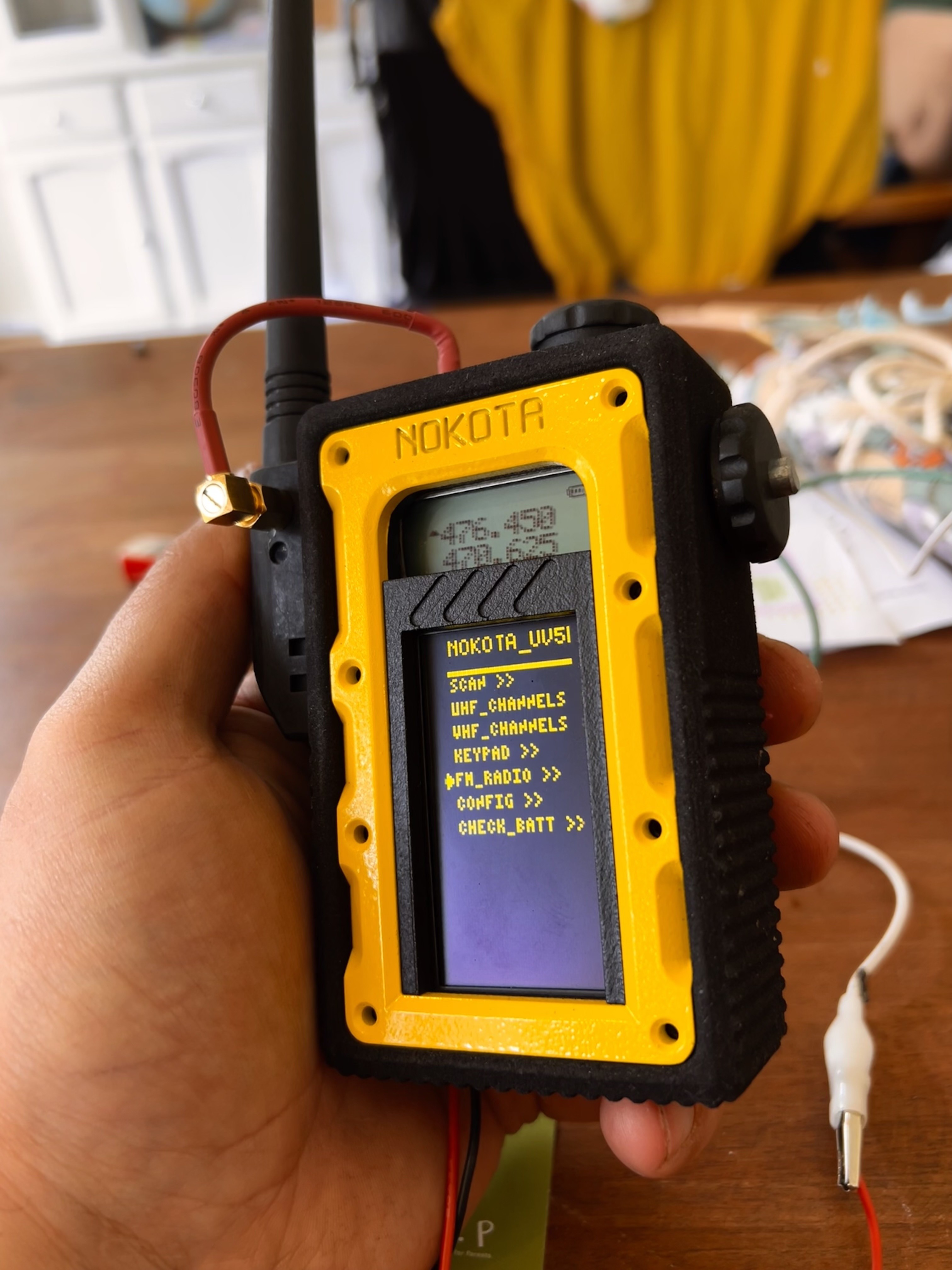
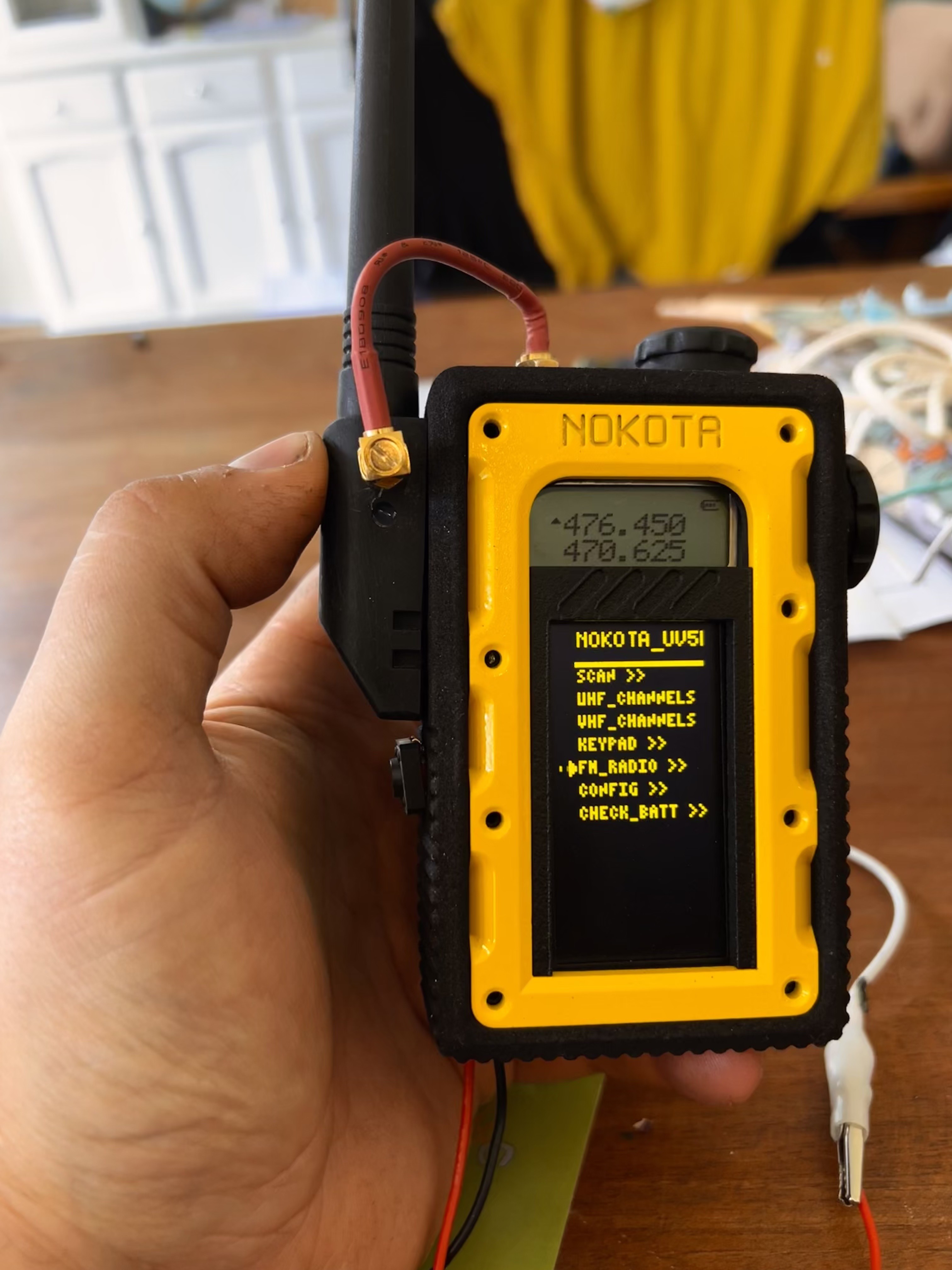
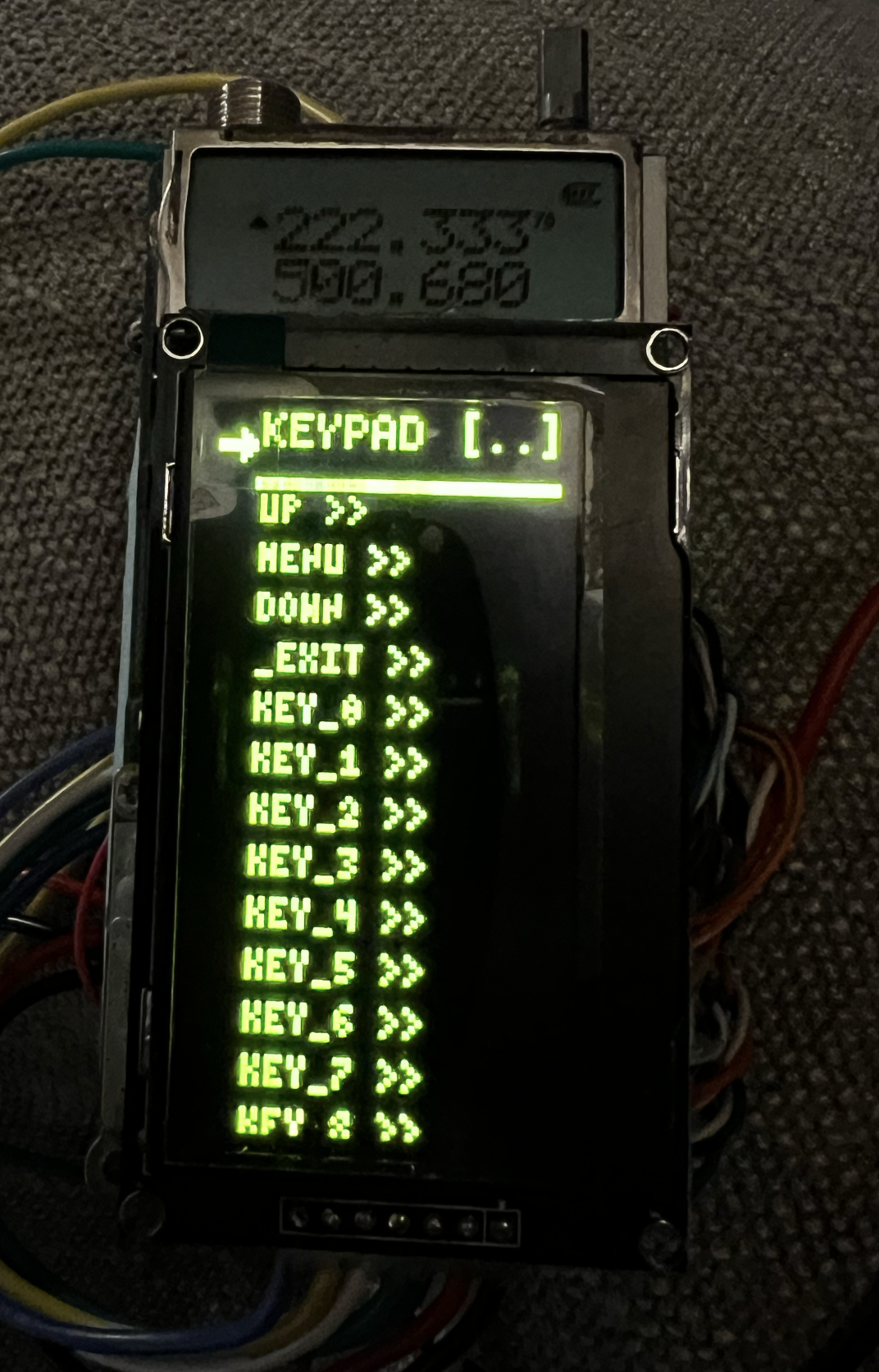
Cyberpunk UV-5R
Hacking a Baofeng UV-5R to turn it into a cyberpunk “Arduino sdr”
 Taylor Hay
Become a Hackaday.io member
Already have an account? Log in.
Just one more thing
To make the experience fit your profile, pick a username and tell us what interests you.
Pick an awesome username
hackaday.io/
Your profile's URL: hackaday.io/username. Max 25 alphanumeric characters.
Pick a few interests
Projects that share your interests
People that share your interests


 Toulon
 Benjamin Blundell
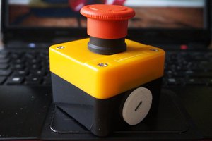
 Ithasu
 The Reverend
Nice work.
I personally would have bypassed the UV5R's internal MCU and re-implemented everything on one MCU that way you don't have to navigate the UV5R menus by pressing buttons using a jog wheel. You could just have a jog wheel native menu system.
To my knowledge those radios use the RDA1846 SINGLE CHIP TRANSCEIVER chip and a RDA5802 Single chip FM Tuner, both of which you can control via I2C.
Additionally for that cyberpunk goodness, it might be fun to add a GPS receiver and switch the MCU from an Arduino to something with a bit more oomph, say an ESP32. This would give you the ability to run APRS quite comfortably. Add a Lora module and you could even make it MeshCom compatible.
Depending on your MCU it may even be possible to add support for WSPR or JS8call. I know they aren't that common on VHF/UHF but WSPR is becoming more popular for beacons so if the MCU could decode it would be very nifty for understanding propagation.
Oh one last thing. With a GPS receiver and a decent MCU and an SD card slot for TLE files, you could have the radio auto tune and auto correct for doppler shift of satellites.
I've been wanting to build what I mention above for a while now, unfortunately I'm terminally ill and don't have the energy to work on such projects any more.