 karen.soledad.quezada
Project improvement ideas
1) SET A PROPER LIGHTINING ENVIRONMENT
Initially, we applied a direct light source, which was reflected by the tape due to its brightness. We removed this light source, which led us to change the image preprocessing filters, using dilate, erode, filter2D, and thresholding. If you apply a non-direct light source, it is likely that the processing parameters and filters used will need to be changed. However, this is recommended regardless. 2) CHANGE YOUR COMPUTER VISION METHOD Thresholding the image between whites and blacks forced us to use white gears to achieve better results. However, due to the lighting, this doesn't seem to be the best option. In a new iteration, we propose applying masks that allow filtering gears of colors like orange or yellow, avoiding issues caused by lights and shadows. 3) SEPARATE GEARS ACCORDING TO THEIR MODULE
This time, we separated the gears based on their number of teeth. Since the applied function also provides an estimated diameter, we propose working with these parameters to calculate their module. This represents an improved use of this program as it would allow you to obtain groups of gears with the same module, which can form functional systems
4) USE AN ENCODER FOR YOUR CONVEYOR BELT
This time, we were unable to improve the encoder available on the conveyor belt, which would have allowed us to accurately estimate the moment when the arm should pick up the gear. This is because the encoder, by providing the speed of the belt and knowing the position of the gear (provided by the function), allows for the calculation of time. In this project, we had to estimate the moment to pick up the gear experimentally. 5) INCREASE THE NUMBER OF TEETH IN YOUR MK2 ARM GEARS
Increase the number of teeth on the gears of the Mk2 arm to have a higher number of steps, enabling more precise movements and reducing backlash.

 esben rossel
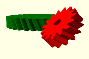
 marciot
 jasonwinfieldnz
 lumbric