Close
0%
0%

Laser4DIY

Laser4DIY is an open-hardware machine for producing PCBs by ablating copper with a laser

Similar projects worth following
Engraving or cutting metal with a typical CO2 laser cutter at a fablab or makerspace is a no-go. These machines emit infrared light, which is reflected by metals like copper used in PCBs, preventing engraving or cutting. However, copper's reflectivity decreases with green or blue light. But while high-power blue laser diodes are affordable, their 2-5 Watts power is insufficient for metal structuring, which requires kilowatts.

This challenge sparked the Laser4DIY project. Since affordable options couldn't ablate copper for PCB production, we began by designing our own open-source laser source. After years of experimentation and development of additional open-source components (including pump laser diode driver electronics, a 4-channel TEC-Controller cooling system, a low-profile motorized XY table, and a safety enclosure), we've created a functional, relatively affordable (around 2000-3000 Euro/USD), and safe machine under an open license.

If you ever tried to engrave or even cut metal with a laser cutter at a fablab or makerspace, you know that it does not work. The usual CO2 laser cutters available there produce infrared light, and metal (especially copper, which is used on PCBs) basically acts as a mirror at these wavelengths. So there is no energy going into the material and it cannot be engraved/ablated/cut this way. Too bad. But the reflectivity of copper is much lower with green or (even better) blue light, why not use one of those high-power blue laser diodes you can get for little money, you may ask. Unfortunately, "high power" does not mean the same thing when talking about laser structuring metal. While these laser diodes usually come with laser power of 2-5 Watts, we are talking *Kilo*-Watts here. This was the starting point of the Laser4DIY project: as all the affordable options commonly available do not work when you want to ablate copper for producing PCBs, we started the design of our Open Hardware machine be designing the laser source itself. Years of experimentation, optimization and developing quite a few additional Open Hardware components on the way (driver electronics for the pump laser diode, a cooling system including a 4-channel TEC-Controller, a low-profile, motorized XY table and a safety enclosure) finally lead to a design, which works, is relatively affordable (material price is around 2000-3000 Euro/USD), is safe to work with, and is published under an open license.

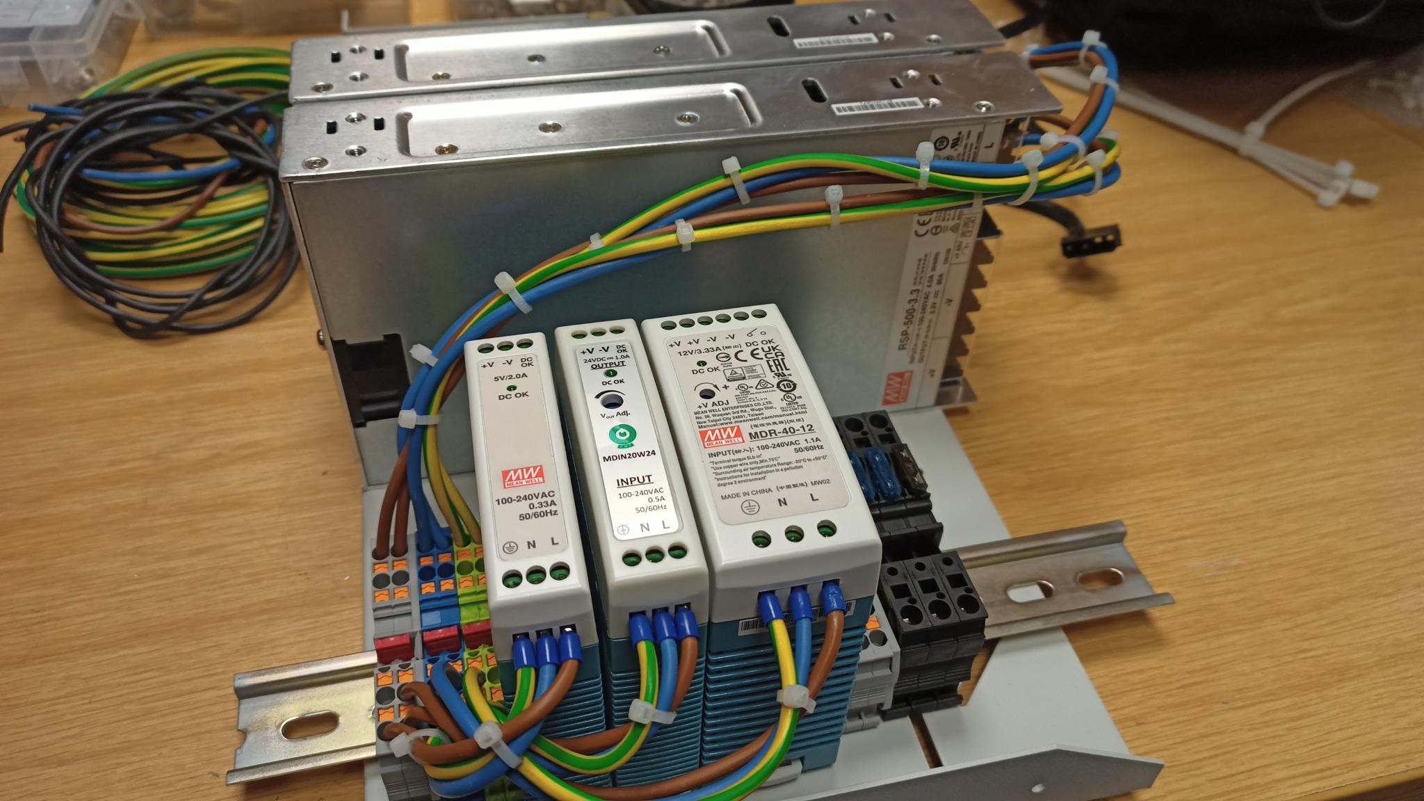
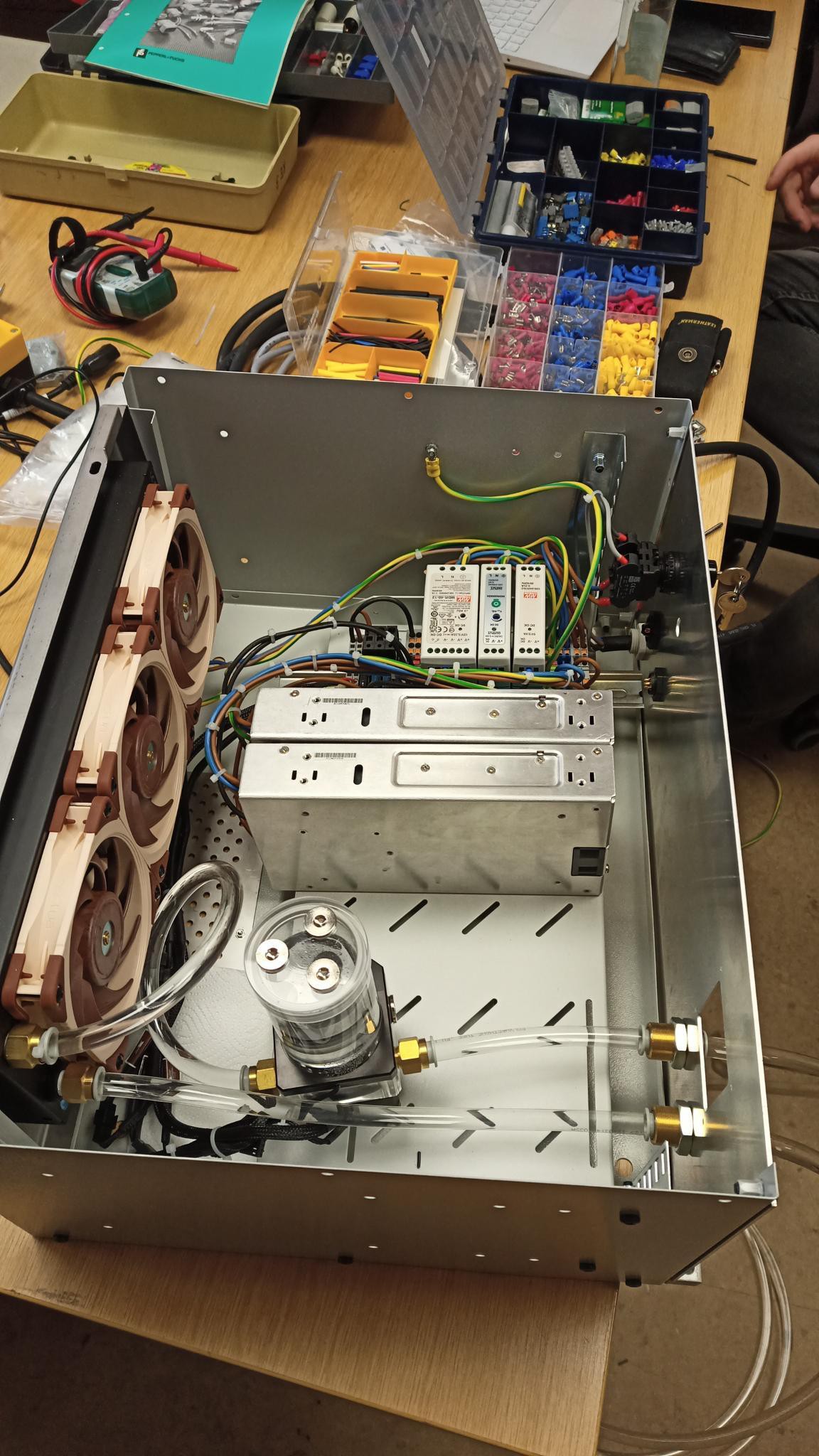
The Laser4DIY machine consists of two parts: the actual laser/structuring machine is placed in a laser safety enclosure made from stainless steel sheets, in which the laser source, the XY table and electronics are located. The power supplies and the cooling system have been moved to a separate supply unit. This offers the advantage that the laser enclosure only contains low voltages of up to 24V, and makes it significantly more compact and lighter.

Exploded view of the Laser4DIY device


The two enclosures (lid of laser chamber is removed for a view on the laser source)

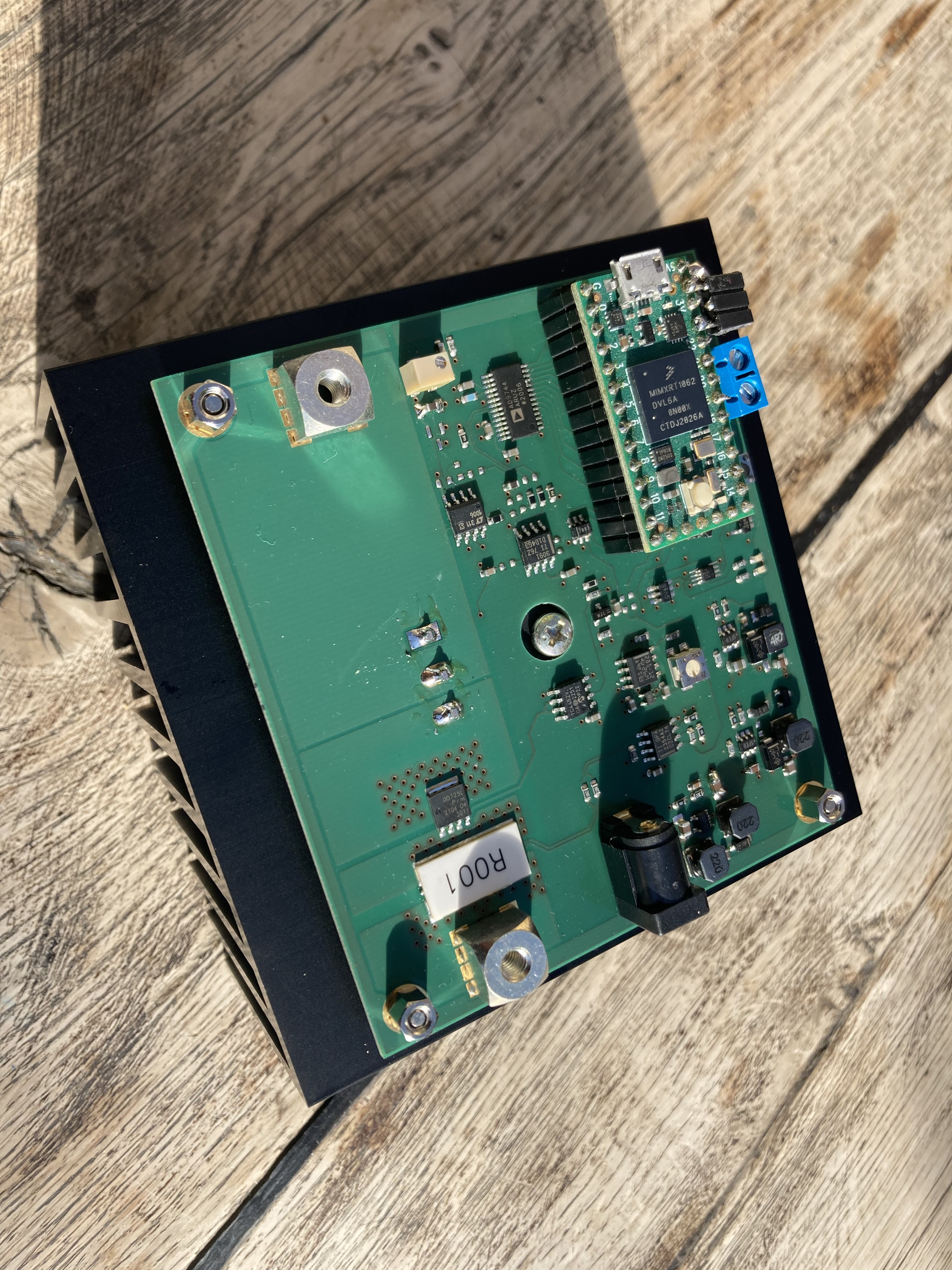
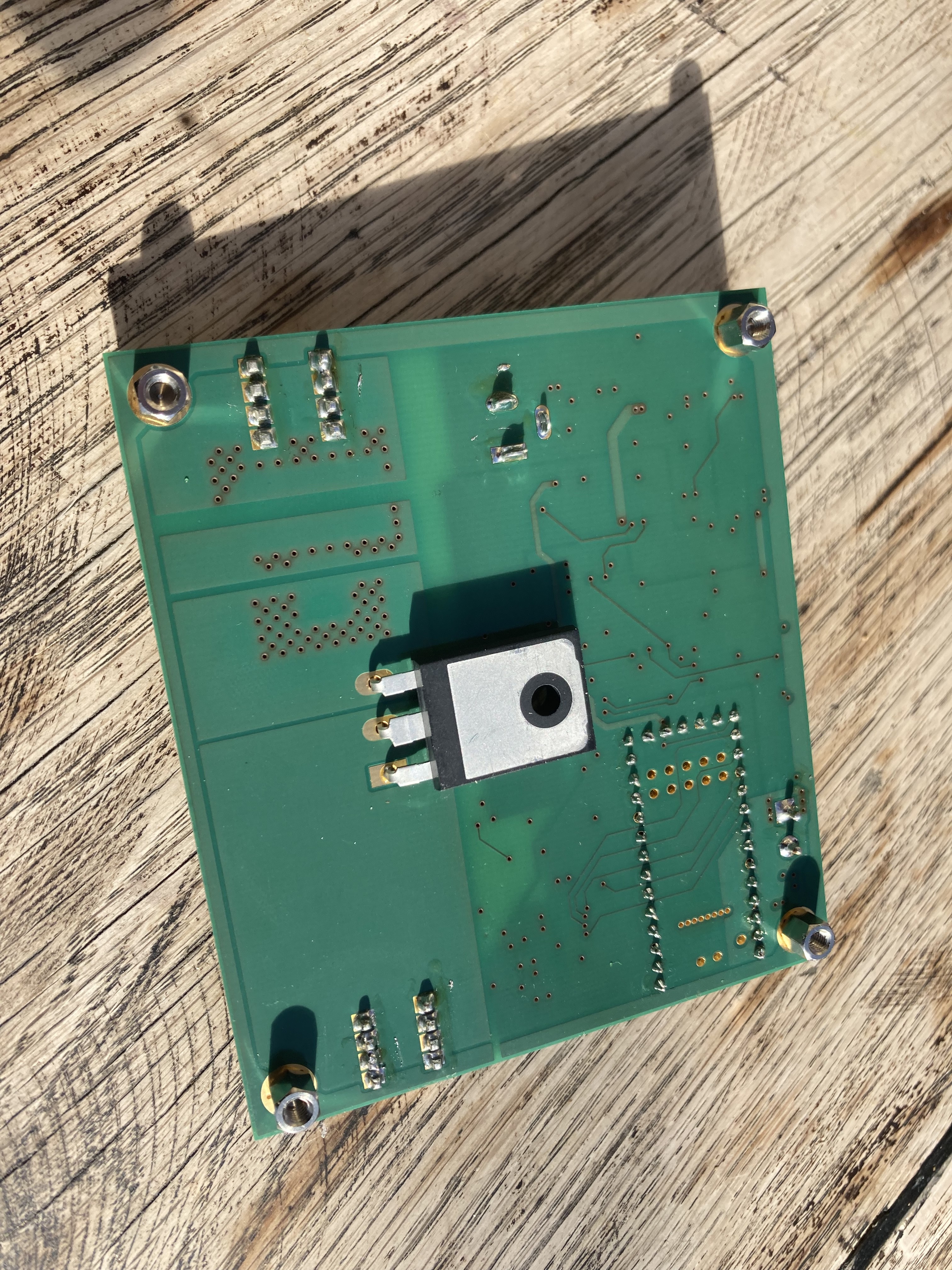
The main enclosure is divided into two parts: The left part contains the electronic components (laser driver, TEC controller, protective circuit, controller for the XY table) as well as the connections for power supply, water cooling and exhaust air. The right part is lightproof and connected to the left part via a "tunnel". Cables, cooling and exhaust air hoses are routed around two corners, so that no light can get into the left part of the case, where it could get out through ventilation openings. The laser source sits on a breadboard made of 8 mm thick laser-cut aluminum and is protected against dirt and accidental contact with a laser chamber made of steel sheet at the top. The laser beam is directed downwards through an opening onto the XY table, where the PCB to be processed is located. For loading, the work table can be moved out to the right side. The cover is secured with safety switches, when opened the laser is switched off. An external suction device is connected via a hose that leads directly under the breadboard to the working point of the arrangement.

With this safety housing, the device meets all the requirements for certification as laser protection class 1, so that it can also be operated outside of a laser protection room.

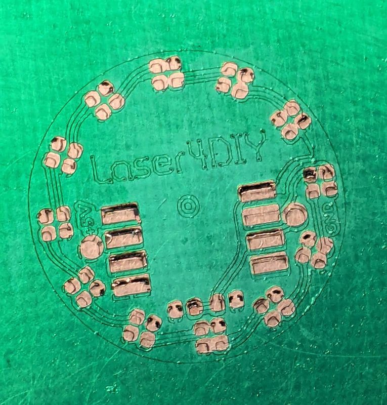
The Laser4DIY laser structuring machine is controlled via USB. You need a CNC control program capable of talking to a GRBL compatible CNC controller, we use LightBurn at the moment. The basic configuration (without optical amplifier) produces laser light with an average power of 0.25 W at λ= 532 nm. This corresponds approximately to a pulse energy of 20 µJ and a peak power of approx. 9 kW. We are using 2 passes with 40 mm/min each to create reliable, electrically isolating ablations. The width of the ablation is approx. 15-20 µm, which enables very fine details.

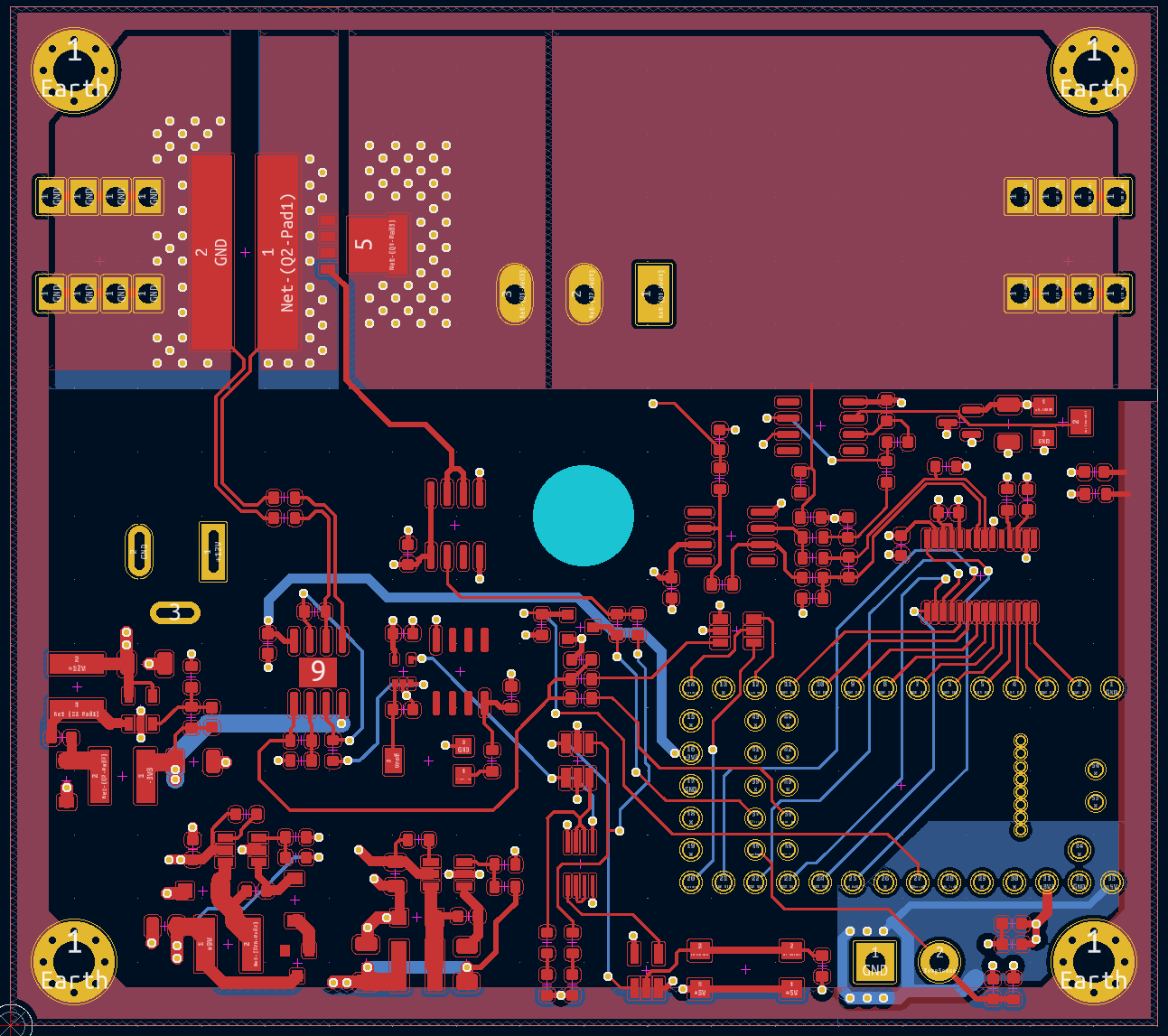
Circuit board created with the Laser4DIY device


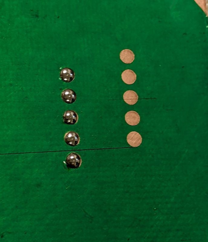
Microscope view of an ablation...

Read more »

View all 6 components

  • New Laserdriver is assembled

    Tobiwan08/11/2023 at 15:50 0 comments

    We assembled our latest version of the laser driver and it is ready for testing:

    Here you can see the underside with the power dissipation transistor before final assembly:


  • Laser4DIY on the Hackaday Podcast!

    FabLab München08/07/2023 at 09:03 0 comments

    In case you missed it: On the July 21 Hackady podcast Elliot and Dan were talking about our Laser4DIY project!

    https://hackaday.com/2023/07/21/hackaday-podcast-228-bats-eggs-lasers-duck-tape-and-assembly-language/

    Lazzzor talk starting at min 29 :-)

    Small correction on what was discussed on the podcast: our pump diode driver is running in constant current mode. We do not pulse the pump diode (yet). But yes, the magic of the q switch works with a cw pump diode too, and we indeed generate pulses ~2.5ns with almost 50kW peak

  • Solder mask laser etching? part 2

    FabLab München07/27/2023 at 12:12 0 comments

    Last time we did a test to see if solder resist film can be laser engraved, see https://hackaday.io/project/191904-laser4diy/log/221159-solder-mask-laser-etching

    That looked quite promising, so we went one step further and tried to put a solder resist mask on a PCB we created with Laser4DIY:

    That worked...  but not exactly great. :-(

    First of all, this PCB is tiny. It's our Laser4DIY Coin made by Alex, measuring only 17mm in diameter. So the pads are tiny as well and that caused issues:

    • The registration is off. We tried to do it using the red pilot laser on the CO2 laser cutter and that is not precise enough. We have to think of better ways
    • The pads are too big in the solder mask. I guess this is caused by the laser spot size. The resolution of our CO2 laser (we used an Epilog Zing) should be sufficient, but simple engraving the exported solder mask pattern does not do the trick. We have to shrink the engraving pattern to compensate for this.
    • And finally, we got ugly dark spots during the process. At many places where the CO2 laser was engraving on previously ablated copper, the underlying FR4 was burned and at some places even causing defects on the copper. We hope that this is a non-issue as soon as we got registration and engraving area right, because if the PCB design is correct, the solder mask should only be removed on copper areas. 

    Definitely need more experimentation in that area...

  • Laser4DIY on the Hackaday Blog!

    FabLab München07/18/2023 at 13:33 0 comments
  • New Diode Driver Electronics Version

    FabLab München07/14/2023 at 07:31 0 comments

    Our new version of the diode driver is coming along nicely! We had a version running already, but it needed a couple of fixes, so here is the new layout. It's manufactured right now, we can't wait to try it out!

    Here you can read up on the new concept: https://wiki.fablab-muenchen.de/display/L4DIY/Laser4DIY+Laser+Diode+Driver

  • Solder mask laser etching?

    FabLab München07/13/2023 at 10:41 0 comments

    When you are done with laser structuring the copper your PCB still is not finished. A proper solder mask is one of the thinks you'd want. Wouldn't it be nice if it could be done with a laser as well?

    We did a quick test with a solder mask film (Bungard Lami). This film is meant to be used with a photo etching process, but maybe it can just be selectively removed with a laser?

    We used a heat press to put the film on the PCB (usually a laminator is used), then put it under a UV lamp for a minute to cure, and threw it into a CO2 laser cutter. A couple of engraving passes at full power later revealed the bare copper. But the question is: is it complety removed so that solder sticks to it?

    We wiped the board with isopropanol and hit it with a soldering iron.

    That worked!

    (These are solder pads with D=2mm)

    Crips edges, takes solder well, very promising!

  • Beta Testing Status

    FabLab München07/11/2023 at 15:39 0 comments

    There are currently two teams trying to build a Laser4DIY device, and beta testing the machine and giving us feedback on the documentation and assembly manual. The teams are located at two hacker/makerspaces, at Das Labor in Bochum, Germany and a team locally here at the FabLab München, which is in Munich, Germany of course.

    The teams started with the motorized XY table and the supply unit. Next thing will be the safety enclosure. Here are some photos of the progress so far:

    Photos: Jan/Andre (Das Labor), Ralf/Felix (FabLab München)

  • Finally on hackaday.io

    FabLab München07/11/2023 at 15:26 0 comments

    OK, it took a while, but finally we are on hackady.io  😁

View all 8 project logs

View all instructions

Enjoy this project?

Share

Discussions

Olviae wrote 07/17/2023 at 08:56 point

there was an article somewhere, they used co2 to cut out copper foil on adhesive very easily, then they could put it on whatever. also make flexible pcbs with it and skulptures.

  Are you sure? yes | no

Similar Projects

Does this project spark your interest?

Become a member to follow this project and never miss any updates