 Sagar 001
Geared Dc motors are used in a lot of hobby projects like in making some kind of robot car and moving robotics. But for precise movement it is very important to use special kind of motors. For example for a balancing robot, we have to use stepper motors (proper stepping of wheel). Because in balancing the movement needed is very precise and normal motor can not complete the task. But there is one solution to these problems where we do not want to use stepper motors but want precise movement then encoder can be used with BO motors.
This encoder just record the rotation speed and direction and convert them into a pulses which can be paired with a microcontroller and driver to precisely change the voltage levels according to the desired pulses needed. These pulse control finally decide the movement speed of motor and using BO motors is very cost effective solution.
How magnetic encoder works:
An electronic magnetic rotary encoder utilizes magnetic fields to measure the rotation of an object. It consists of a magnetized rotor and a stationary sensor. As the rotor rotates, the sensor detects changes in the magnetic field and converts them into electrical signals. These signals are processed to determine the rotational position, speed, and direction of the object. The sensor can be based on various technologies, such as Hall effect sensors or magneto resistive sensors, which detect the magnetic field variations. By analyzing these signals, the encoder provides accurate rotational data, making it useful for applications such as motor control, robotics, and industrial automation.
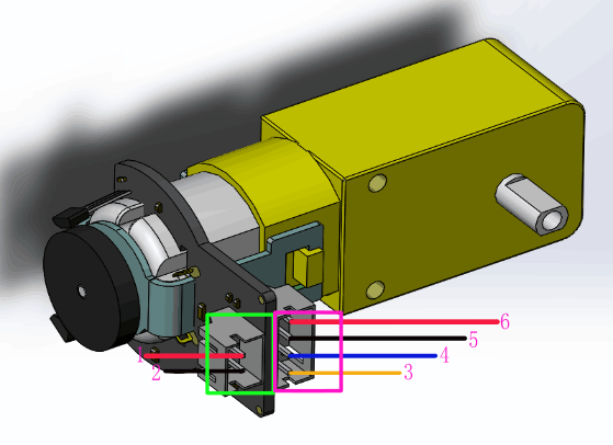
A simple encoder consists of 4 wires (2 for power and 1 for interrupt and other 1 for rotation direction). Microcontroller never checks for any motion recorded by encoder, but encoder by itself by generating an interrupt tells the microcontroller and the step is recorded.
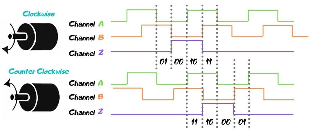
Encoder A (labelled C1, PinA) of the motor connects to pin 2 of the Arduino. Pin 2 of the Arduino will record every time there is a rising digital signal from Encoder A.
Encoder B (labelled C2, PinB) of the motor connects to pin 3 of the Arduino. The signal that is read off pin 3 on the Arduino will determine if the motor is moving forward or in reverse.
Gear motor and Encoder Specs:
Here I have a BO motor from DF robot, It is a geared motor with 120:1 gear ratio (1 output shaft movement when motor rotates 120 times). It has an integrated quadrature encoder that provides a resolution of 8 pulse single per round giving a maximum output of 960 within one round.
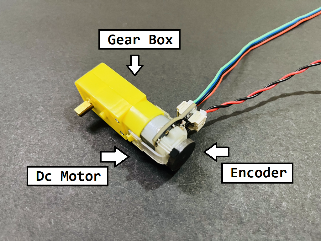
- Gear ratio: 120:1
- No-load speed @ 6V: 160 rpm
- No-load speed @ 3V: 60 rpm
- No-load current @ 6V: 0.17A
- No-load current @ 3V: 0.14A
- Max Stall current: 2.8A
- Max Stall torque: 0.8kgf.cm
- Rated torque: 0.2kgf.cm
- Encoder operating voltage: 4.5 to 7.5V

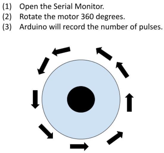
Encoder value calculation: Encoder pulse per revolution = 8 One rotation of output shaft = Encoder pulse per revolution X Gear Ratio So pulse per one rotation = 8 X 120 = 960 Pulse per revolution.

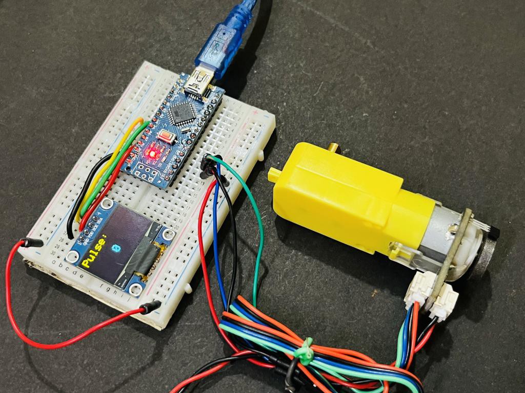
Code for Pulse Calculation:
// Encoder output to Arduino Interrupt pin. Tracks the pulse count.
#define encoder0PinA 2

// Keep track of the number of right wheel pulses
volatile long right_wheel_pulse_count = 0;

void setup() {

  // Open the serial port at 9600 bps
  Serial.begin(9600);

  // Set pin states of the encoder
  pinMode(encoder0PinA , INPUT_PULLUP);

  // Every time the pin goes high, this is a pulse
  attachInterrupt(digitalPinToInterrupt(encoder0PinA), right_wheel_pulse, RISING);
  // 2Nd method to use Interuppt pin (Either use PIN 0 or use funtion digitalPinToInterrupt
}

void loop() {

    Serial.print(" Pulses: ");
    Serial.println(right_wheel_pulse_count);
}

// Increment the number of pulses by 1
void right_wheel_pulse() {
  right_wheel_pulse_count++;
}
Code for Velocity of motor:
This code reset the encoder counter after every rotation which gives the precise number of turns done by motor per unit time.
//The sample code for driving one way motor...
Read more »
 JP Gleyzes
 Danny FR
 justin.richards
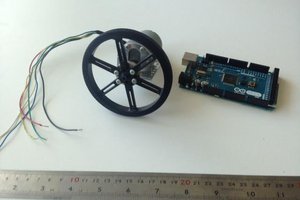
 Ozan Enginoglu