 Dave Ehnebuske
Introduction
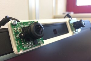
To make the camera I wrote a bit of firmware for the ESP32 CAM and built a simple "camera body" with interchangeable pinholes, The firmware is in the linked github repository.
The idea is to use the ESP32 CAM board and camera as a "point and shoot" camera that saves the pictures it takes to an SD card inserted into the SD card slot built into the ESP32 CAM board. The firmware will work "out of the box" with the lens and camera unmodified, but I wrote it so I could take pinhole camera photos for a local photo show.
The only controls are a switch that acts as the shutter release and the board's built-in reset button. To use the camera, power up the ESP32 and wait for the built-in red LED to flash five times. (There are two LEDS on the board. The red one is marked LED1 and is on the side of the board with the processor. The other is the white "flash" LED on the camera side.) Once the red LED flashes, the camera is ready. If it repeatedly flashes, pauses and flashes again, count the number of flashes in a group to figure out what went wrong:
    Flashes  Problem
    =======  ====================================
          2  Camera initialization failed
          3  SD card file system mount failed
          4  No SD Card found in the card reader
To use the camera, click its shutter. The red LED will flash once to indicate that the image was captured and saved. If the red LED doesn't flash, something went wrong. Maybe I'll add more error indicator LED flashing if this turns out to be a problem, but so far it hasn't.
Activity on the SD card occurs at two only points. First, during initialization. And, second, after the shutter is pressed but before the red LED flashes to indicate the image was captured. So, it should be okay to pull the power on the camera at other times.
If the shutter isn't clicked for five minutes the camera will flash the red LED five times and go into deep sleep mode. To get it going again, press the reset button on the board.
Camera Construction
The body of the camera is laser cut from 3mm Baltic birch plywood. Here are the parts:
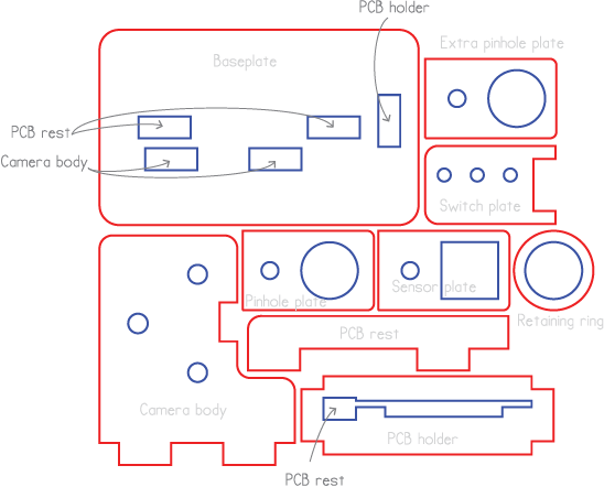
There's also an SVG file of this if you'd like to cut your own. The parts in the drawing are not kerf-compensated. The retaining ring is only needed for longer focal length pinholes.
The pinholes are each made from thin kitchen aluminum foil stretched over one end of a 4mm length of thin-walled, 10.33mm o.d. brass tubing. (It's 3/8-inch i.d. stuff I had around the shop.) For the shortest focal length pinhole, the tube and foil are press-fit into the pinhole plate to form the pinhole assembly. For longer focal lengths, the pinhole assembly is formed by press fitting the tube and foil into the retaining ring and then press fitting the other end of the tube pinhole plate. The ESP CAM sensor, with its lens removed is placed in sensor plate to form the sensor assembly. The pinhole and sensor assemblies are stacked together and attached to the body of the camera with an M-3 screw that goes into a heat-stake nut pressed in from the back of the plywood camera body. The brass alignment pins in the camera body above and below the pinhole and sensor assemblies are made from 2.9mm diameter driver pins for pin-tumbler locks. The pinhole assembly is removable to allow pinhole assemblies with different focal lengths to be used. The shutter switch is a microswitch from my stock.
The Pinhole
The ratio of the distance from the pinhole to the sensor (the "focal length") to the diameter of the pinhole (the "entrance pupil") is called the f-stop or focal ratio. For a pinhole camera to work at all well, the f-stop needs to be at least 32. Preferably higher. We can make the focal length whatever we want by moving the pinhole farther from the image sensor. A long focal length means the pinhole diameter can be bigger for the same f-stop, which makes it easier to make. But a long focal length also narrows the field of view that the camera sees. Here's a diagram showing a cross section of...
Read more »


 AIRPOCKET
 Xabi Z
How did you arrive at a pinhole diameter of 0.125 mm for a 4 mm focal length? The hole size for a good image is given as 0.0366 x sqrt of focal length as per Wikipedia. I tried a pinhole size of 0.075 mm but could not get an image due to the light level being too low. The exposure time is automatically controlled - I could not change it manually. With a larger pinhole size I obtained an image that is fuzzy, as in your photo. I have seen photos taken with a non-digital pinhole camera that are well defined. There are also very small pinhole surveillance and spy cameras that are able to get well defined images. How do they achieve that? Thank you.