Woody is a work in progress, see project logs for details.
Woody is scheduled for exhibition at OC Maker Faire on October 21, 2023
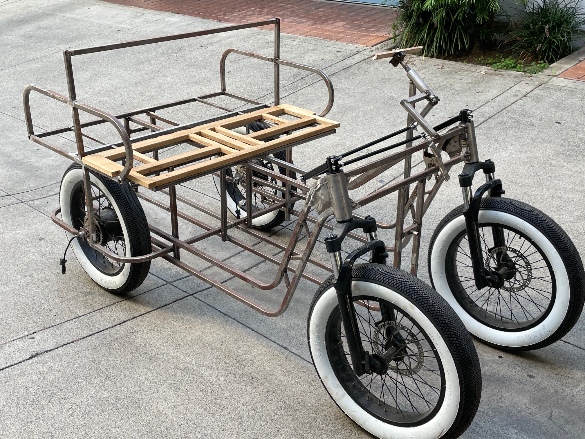
Woody is a scratch built quad wheel bicycle with four passenger capacity, with electric power to assist pedaling.
Already have an account? Log in.
To make the experience fit your profile, pick a username and tell us what interests you.
Woody is a work in progress, see project logs for details.
Woody is scheduled for exhibition at OC Maker Faire on October 21, 2023
well, not many updates for 3 weeks, but mucho progress. In somewhat chronological order:
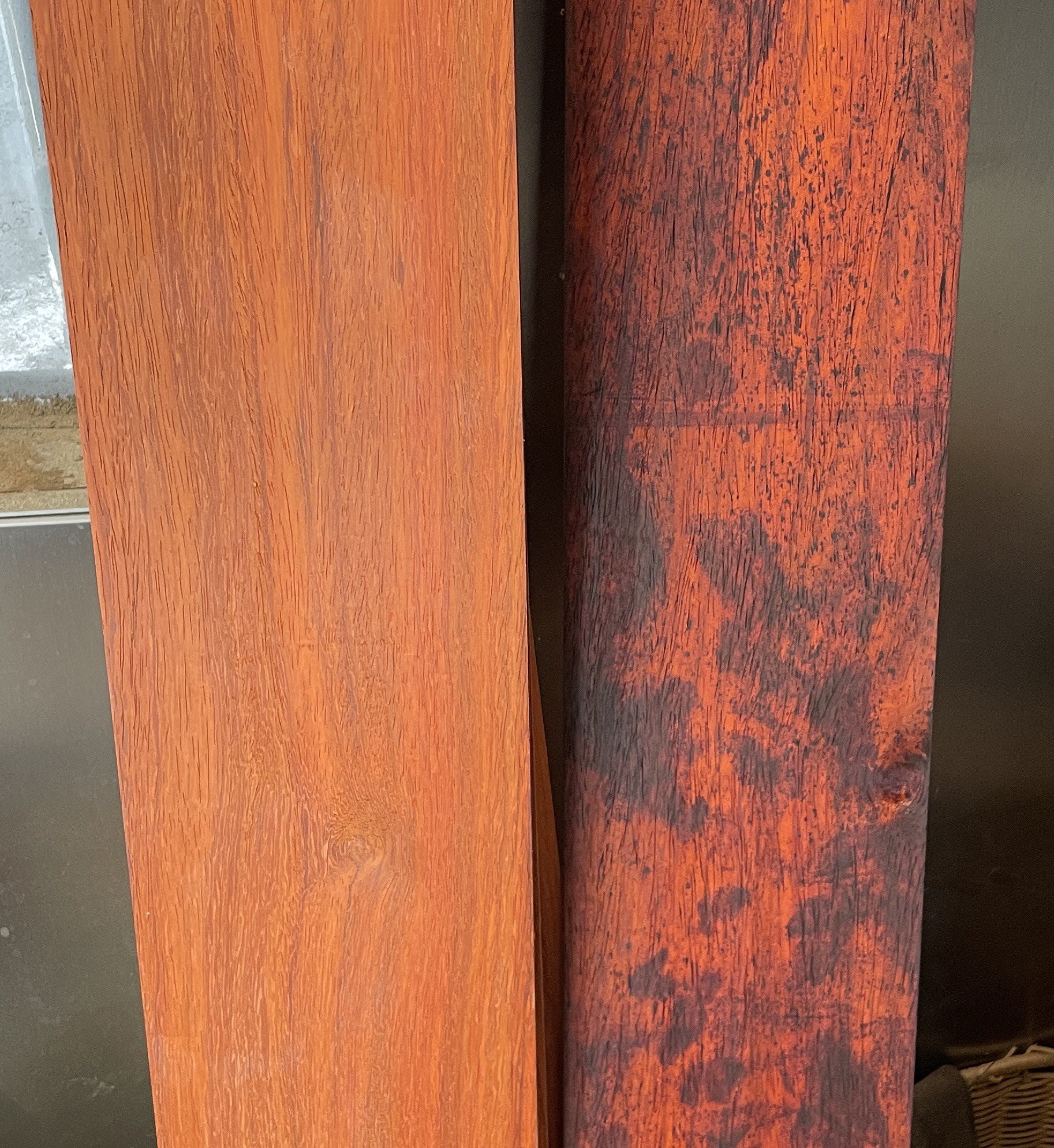
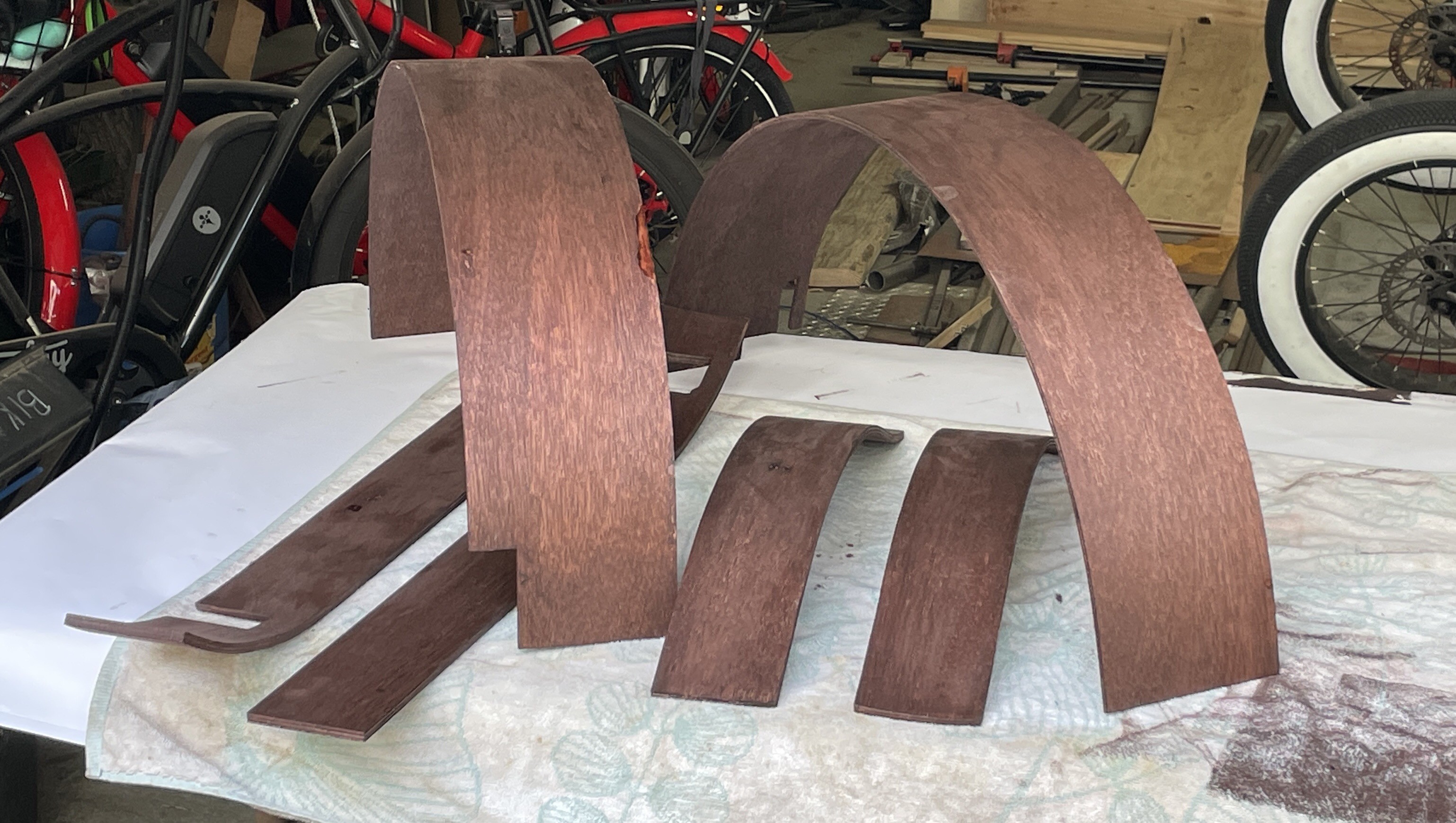
The padauk was abandoned. It did not respond well to steaming, becoming black spotted, and not very bendable either!
 so I switched to generic 0.1” luan ply wood. I was able to use 2 layers for the fenders, and 3 layers for the running boards.
this is before staining, and this is after.
next up was stripping all the components, checking all the welds, grinding, then off to powder coating!
 We selected Illusion Rootbeer Brown.
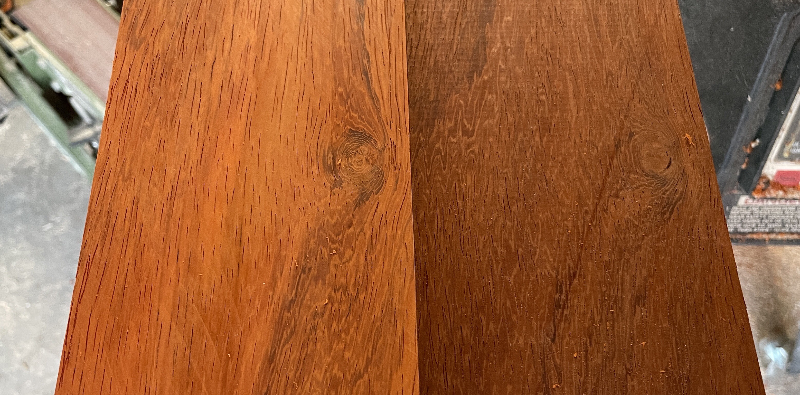
This is padauk, an African hardwood. This has been resawn to about 7mm thick. At left is a freshly sawn surface, and right is one which has aged for many months.
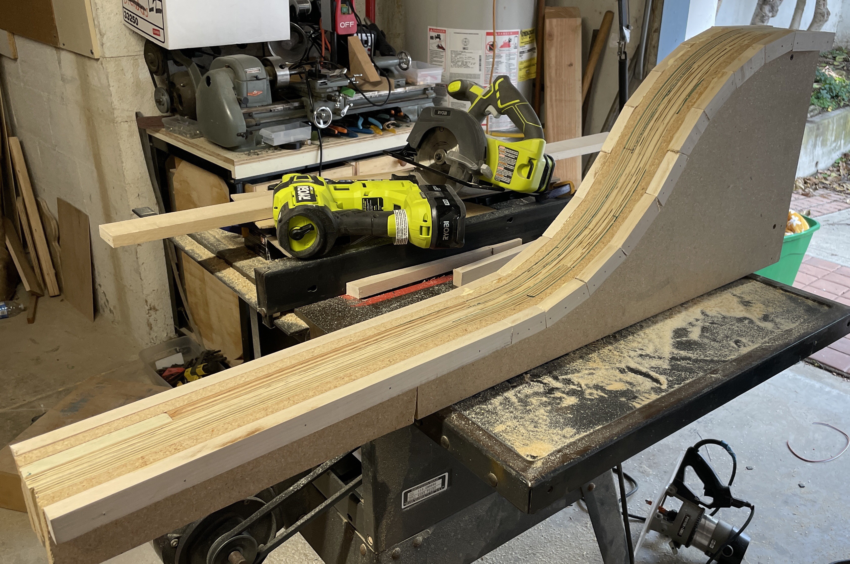
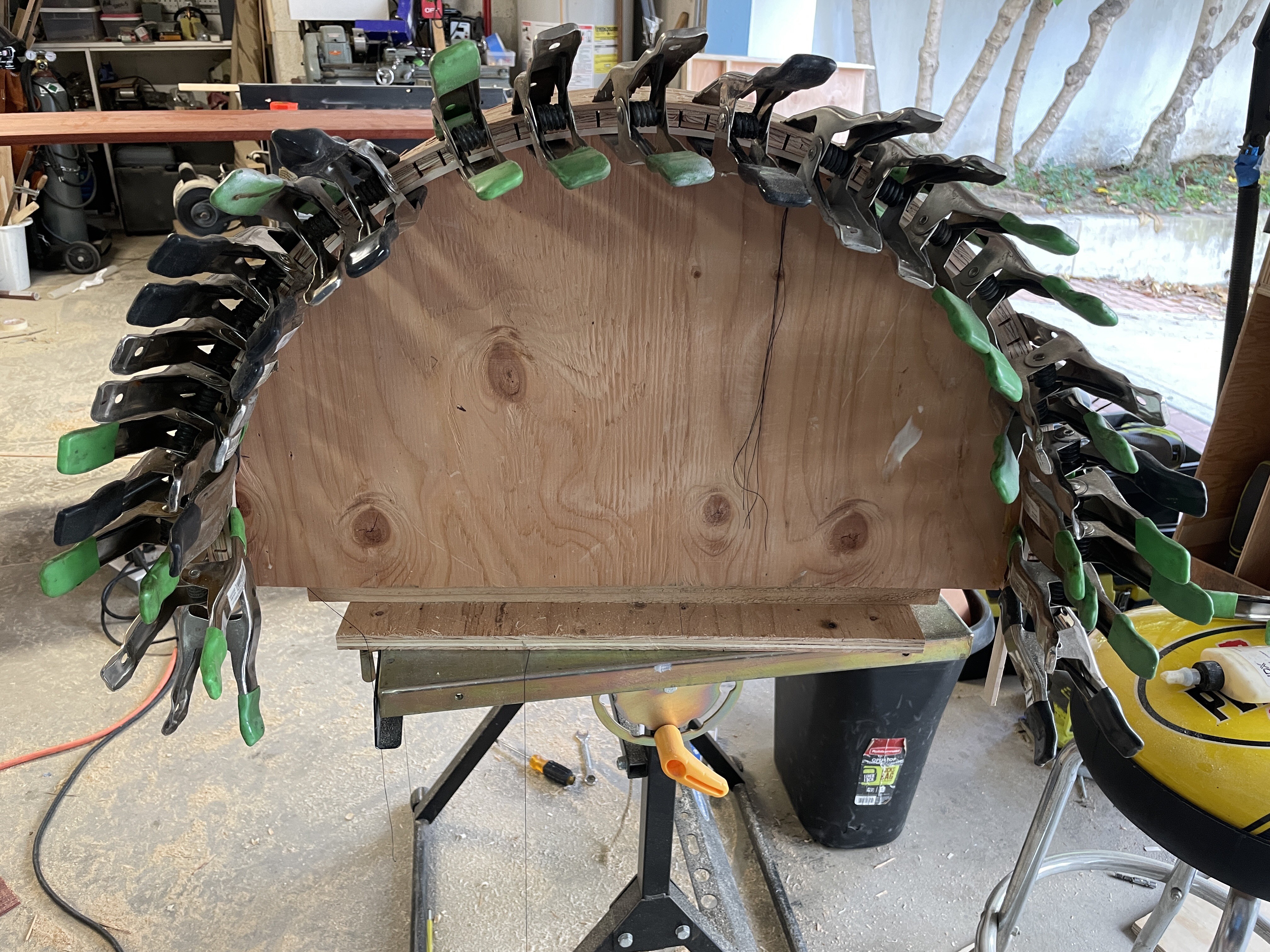
Next is the form for the running boards and front fenders.
after that is the form for the rear fenders. A bit easier as it is a bit more than half of a circle.
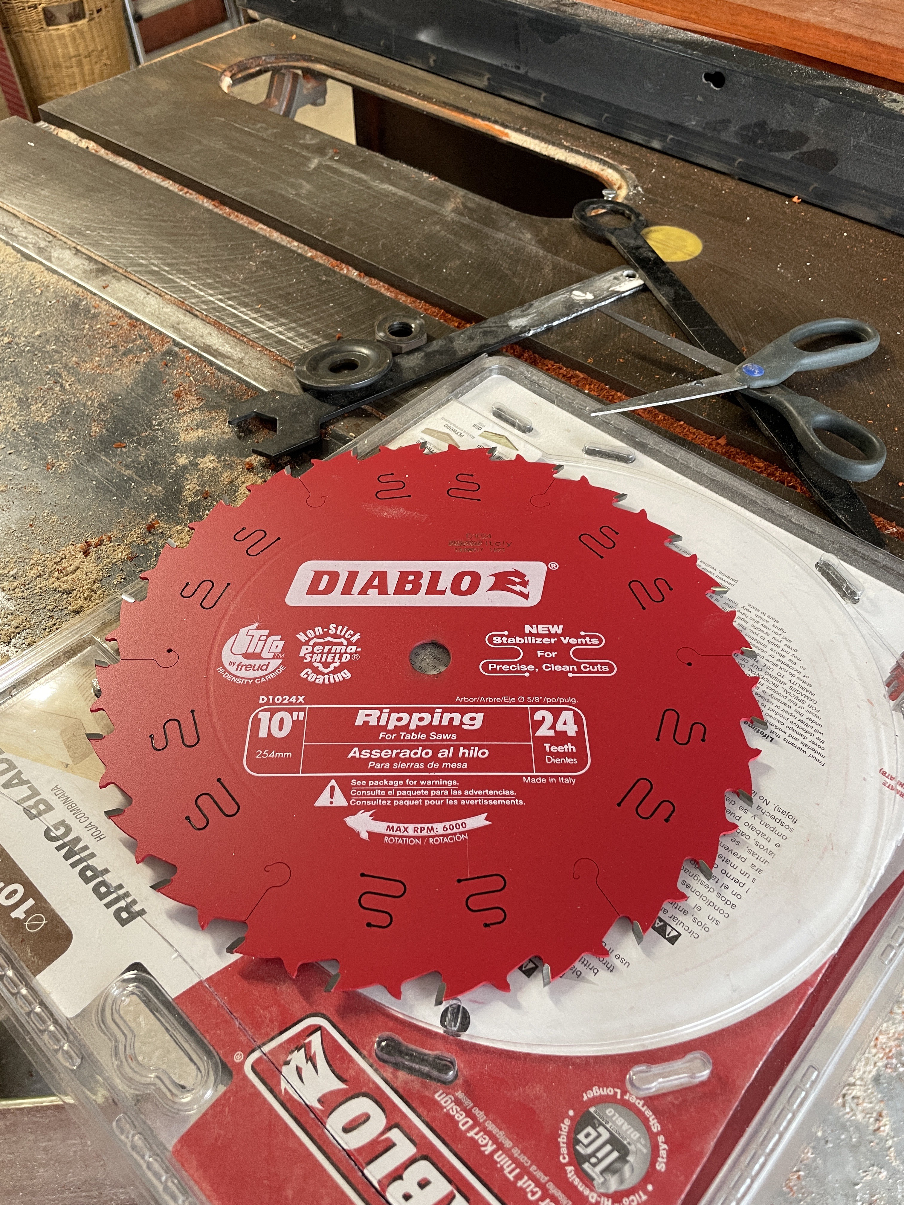
And, a new rip blade used for reshaping the padauk.
the electric system on Woody will be tricky. Two Bafang motors with their 9 signals, extending over a longer distance, to a a pair of controllers intended for dual drive use, but with sketchy documentation and random connectors.
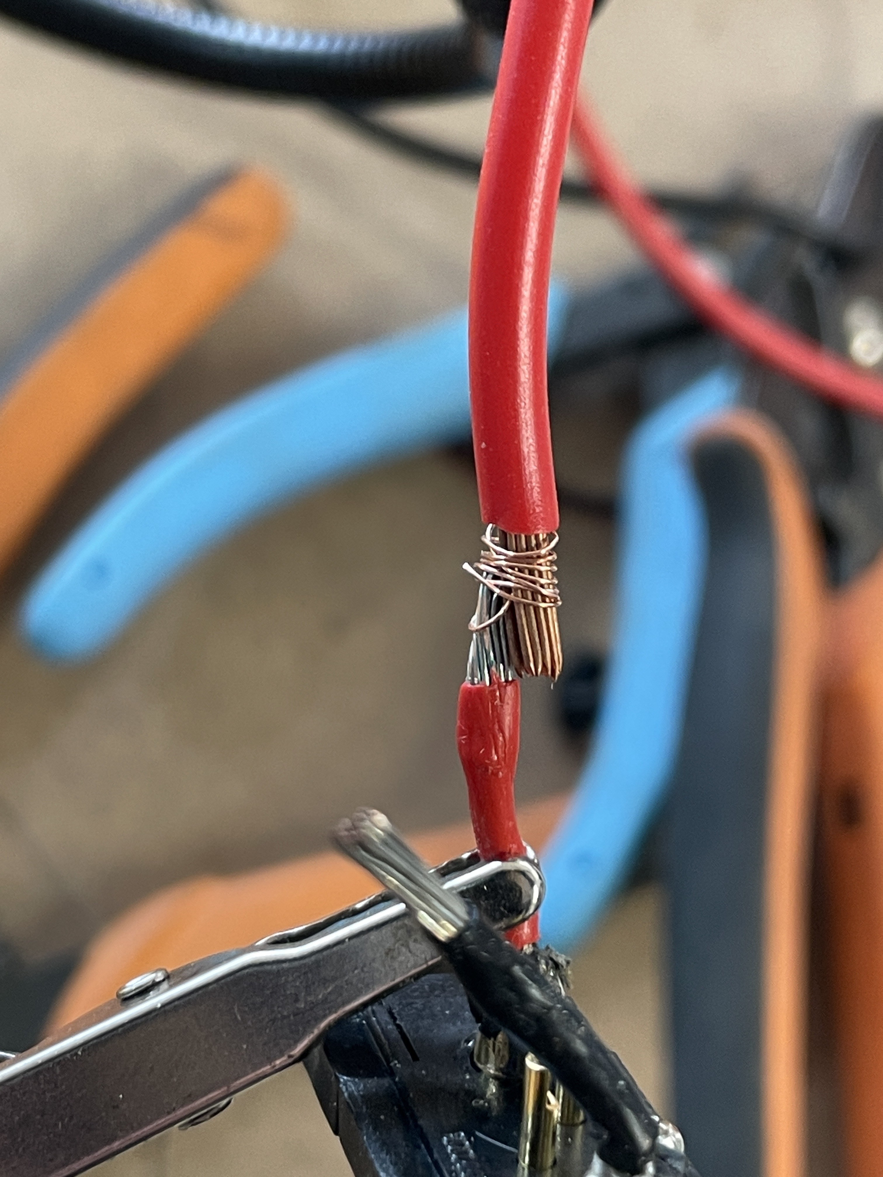
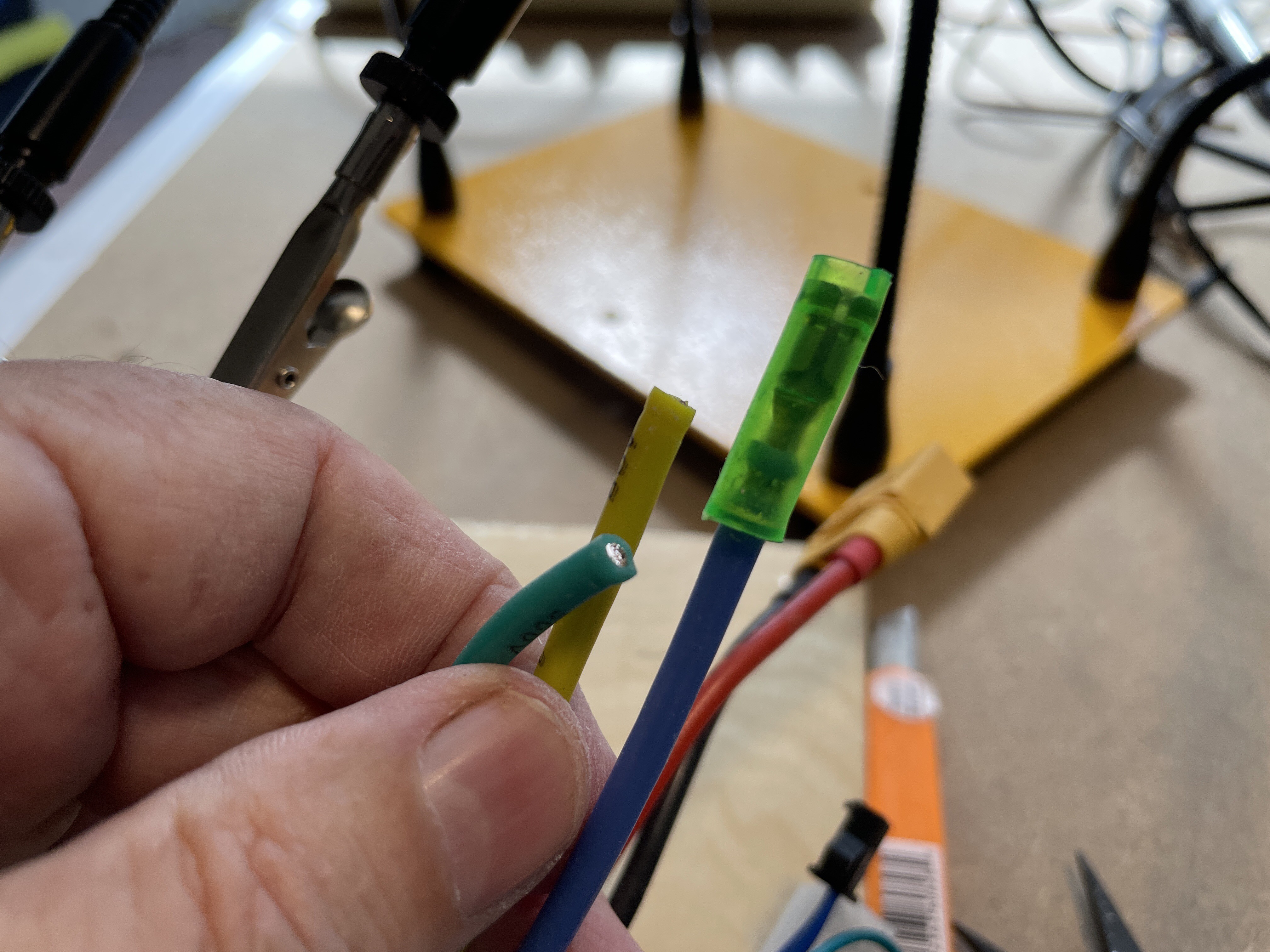
The plan is to cut the connectors away and shorten the cable from the hub. These were about 16g wires for the phases, about 28g for the signal wires. I used 14g to splice into the phase wires near where they exited the hub. I used a piece of copper strand to tie the two wires together before soldering, see below. This picture is actually battery positive, not a phase wire, both about 16g. Batteries connect with XT90 connectors, to an X harness connecting the two batteries in parallel, then splitting out to two leads with XT90s to power the controllers.
next the phase wires were spliced to a multi conductor cable. Each splice was protected with heat shrink.
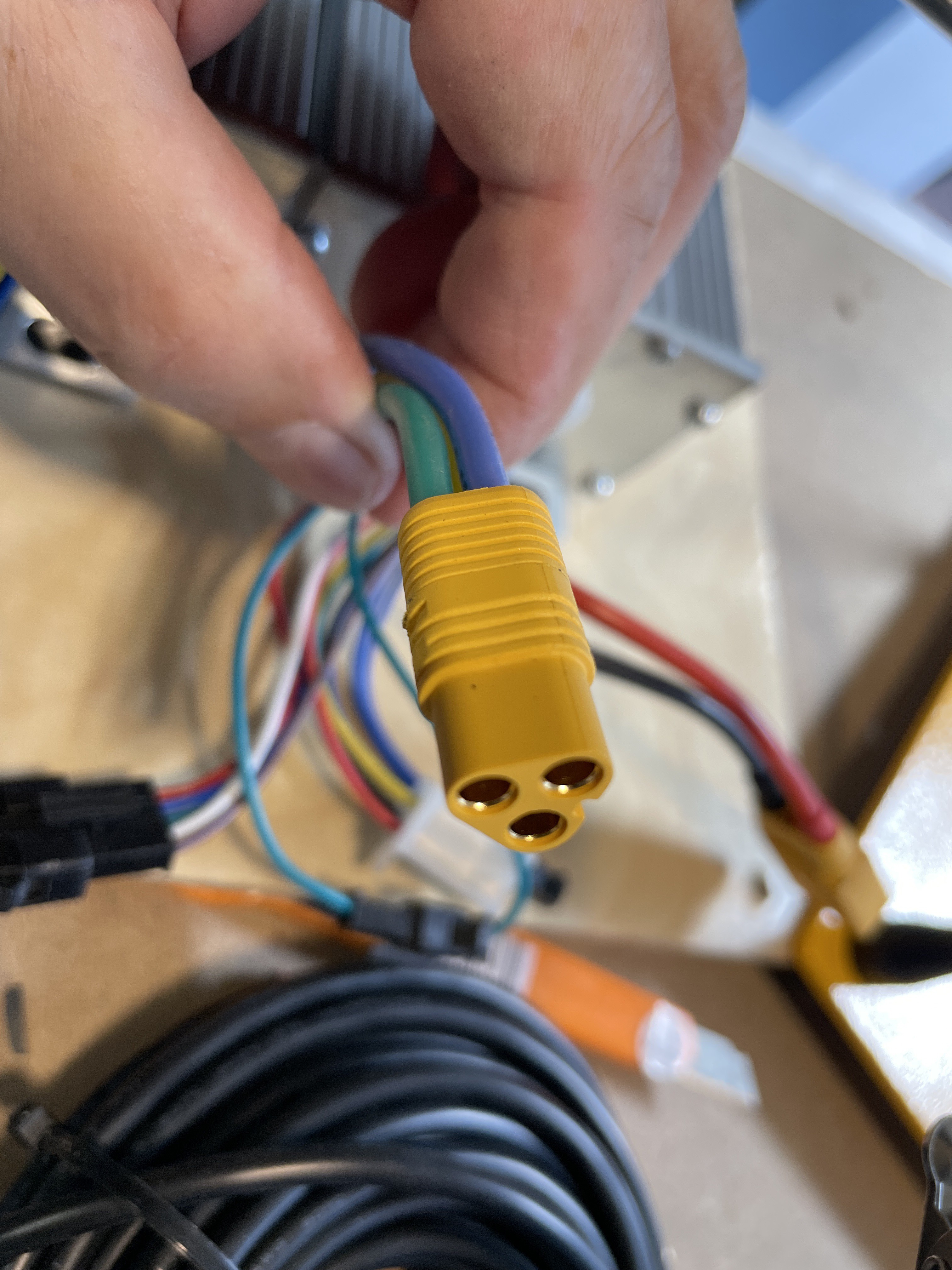
The motor had some sort of bullet plugs for the phase wires, I changed this to an MT60 connector.
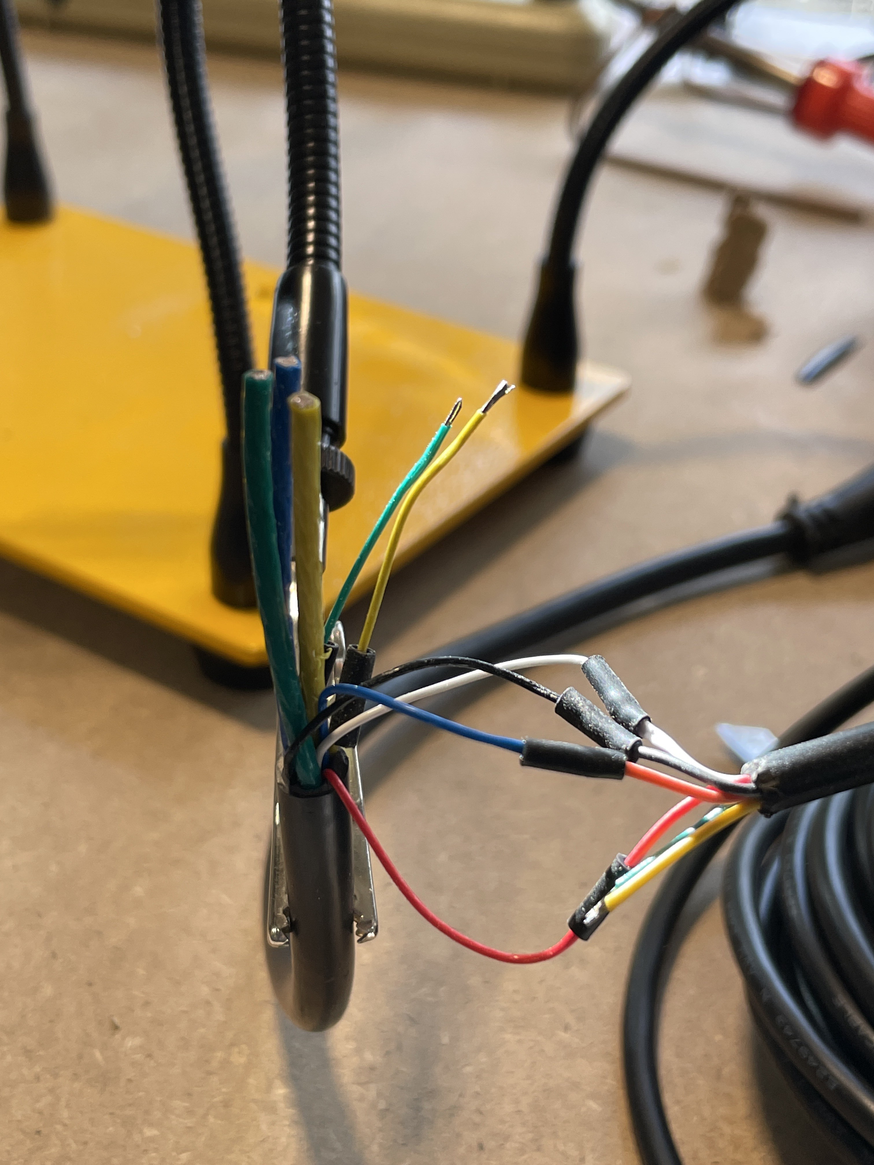
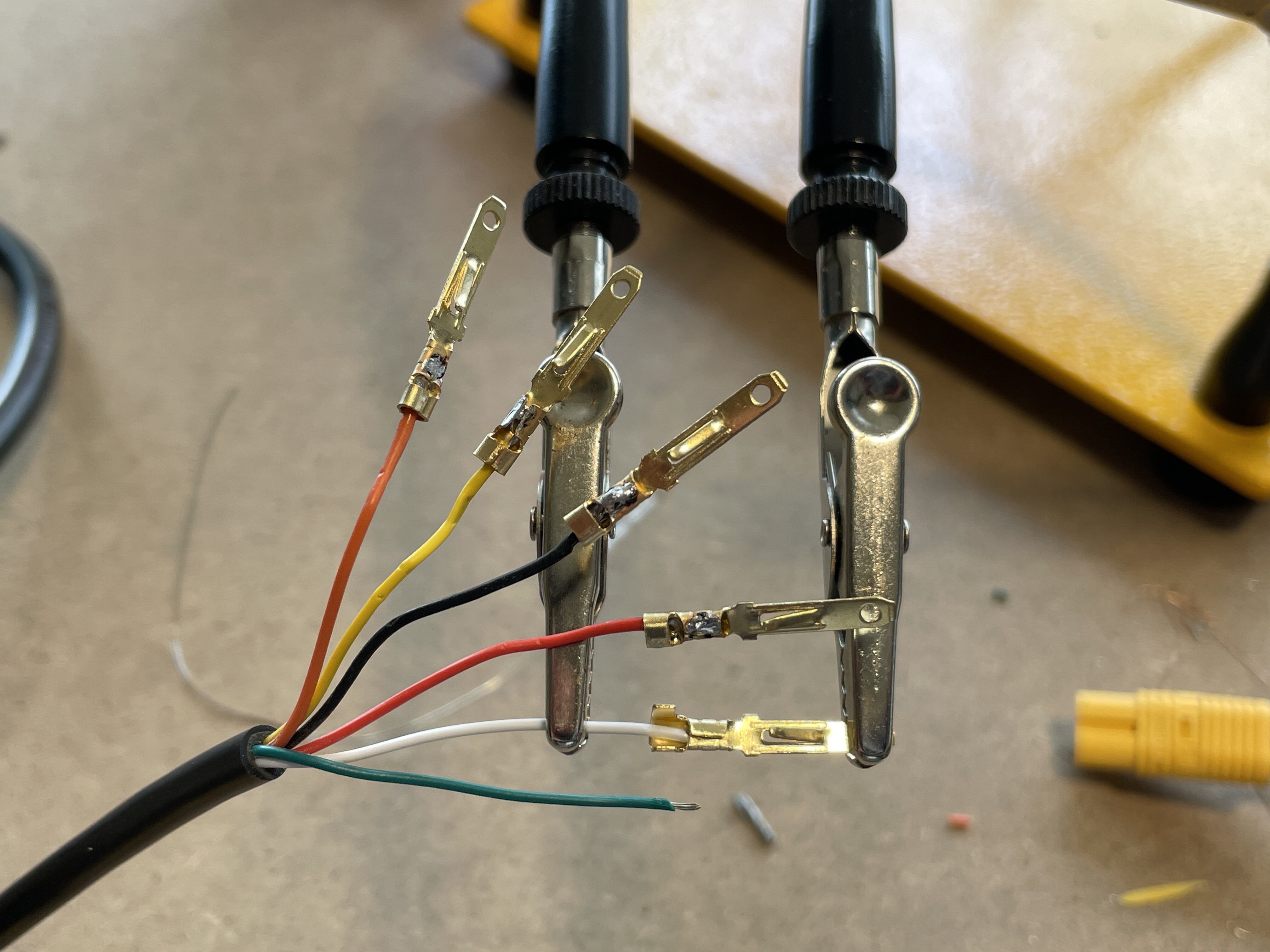
for the Hall sensors and 5V etc the controller used this 3.8mm connector. I was able to buy a kit with 2,3,4,6,9 positions in each polarity, and a bunch of crimp on contacts.
The gauge was a bit small to be crimped so had to tin first, crimp, then solder.
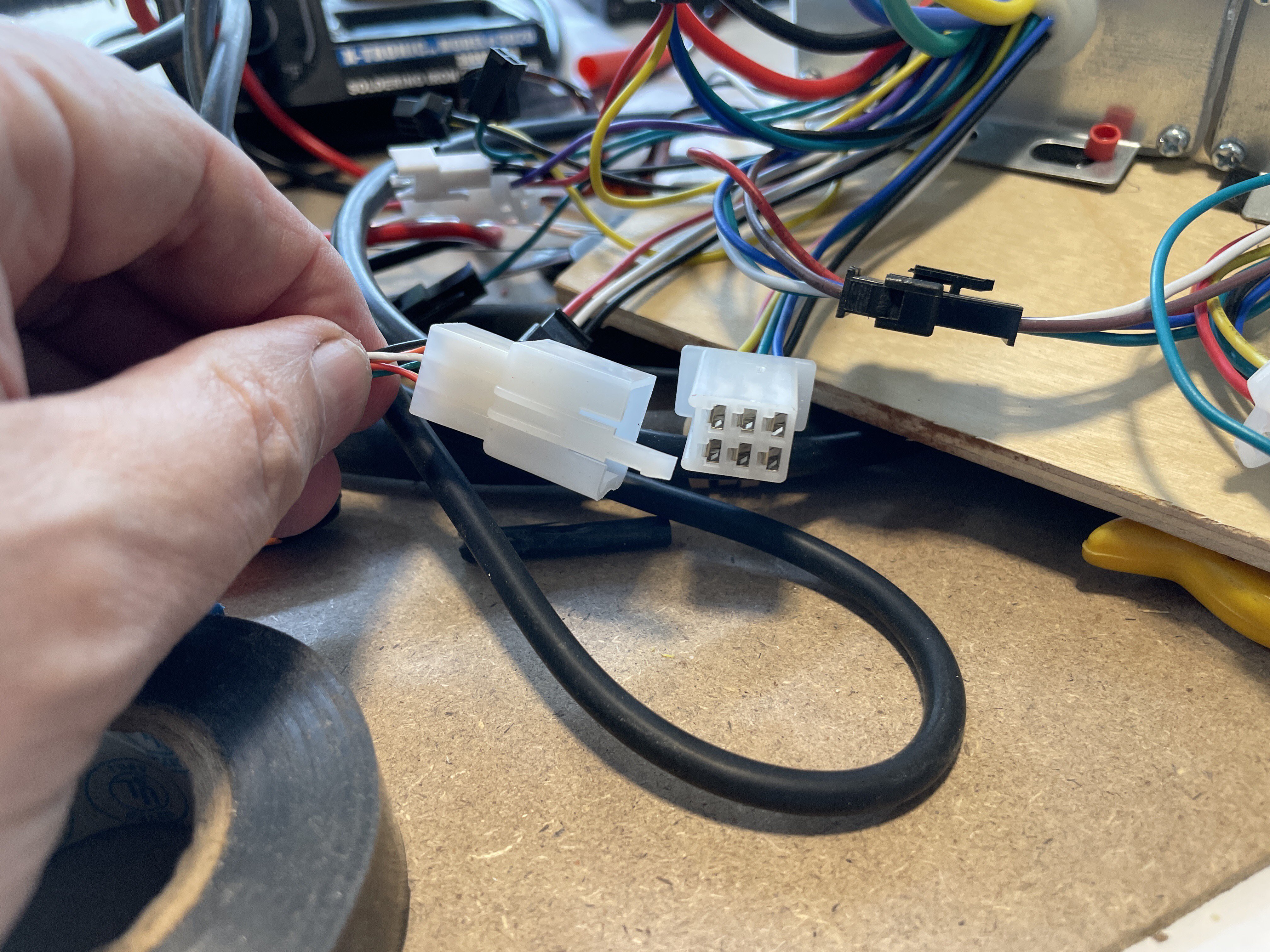
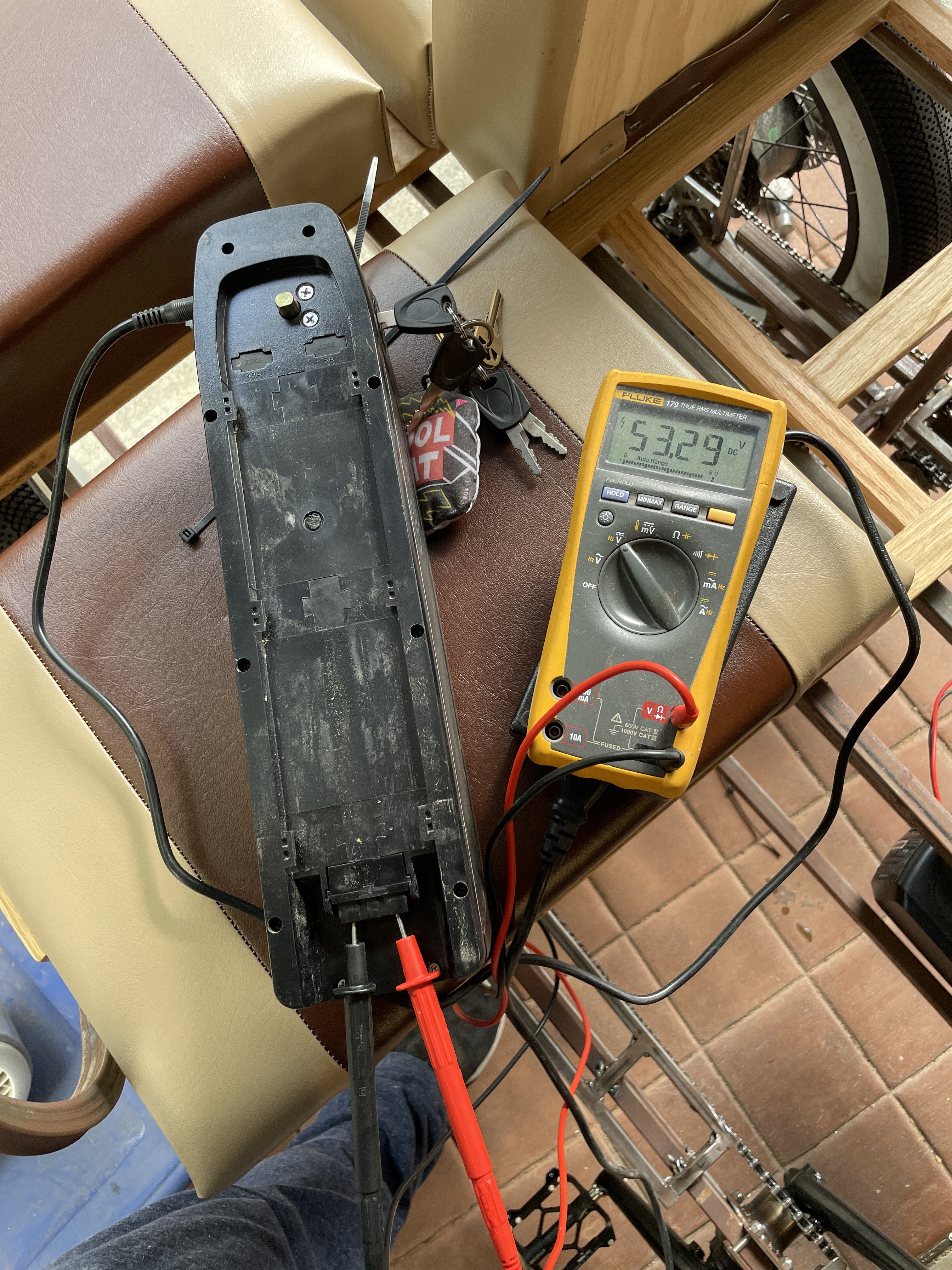
One battery was a bit below the other, so 15 minutes of charging brought it within a couple milivolts. I then plugged they X harness which connects to two batteries to the two controllers, with batteries tied together in parallel.
So, does it work you ask? Well, somewhat. One motor functions but has very little power, the other had nothing. So next up, debug!
in the run up to Maker Faire OC, a few things were completed. The top was removed, and the stringers were glued into place as well as on to another.
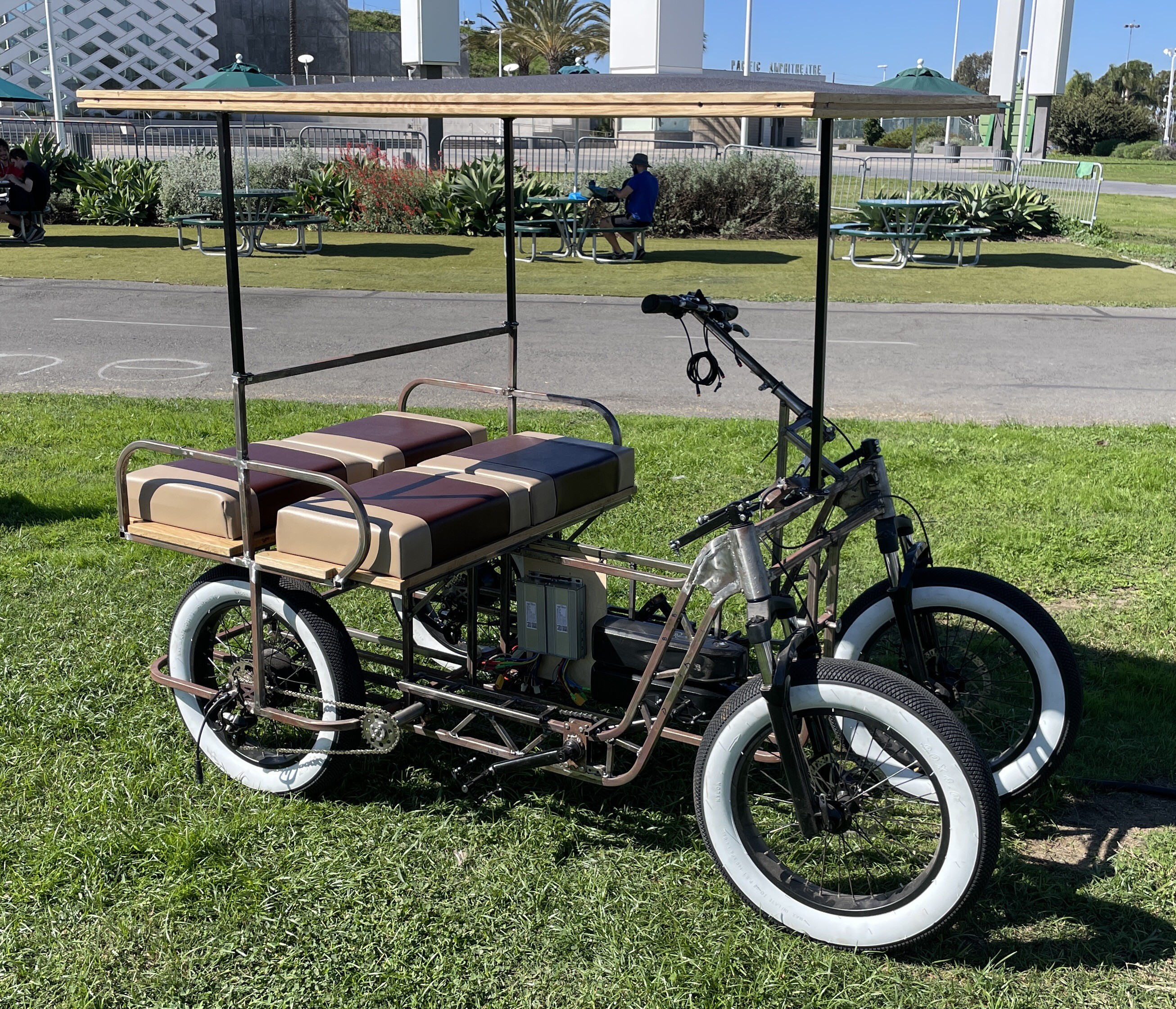
Then the shade cloth was added. I used a dado 1/8” wide by 1/4” deep, and some 1/8” screen spline. It took about 30 minutes to work my way around, getting the spline fully embedded. After the spline was in place, I was able to chase around with a sharp knife, cutting off the excess, results shown below. This method withstood a trip in the back of a truck a bit over 40mph without loosening.
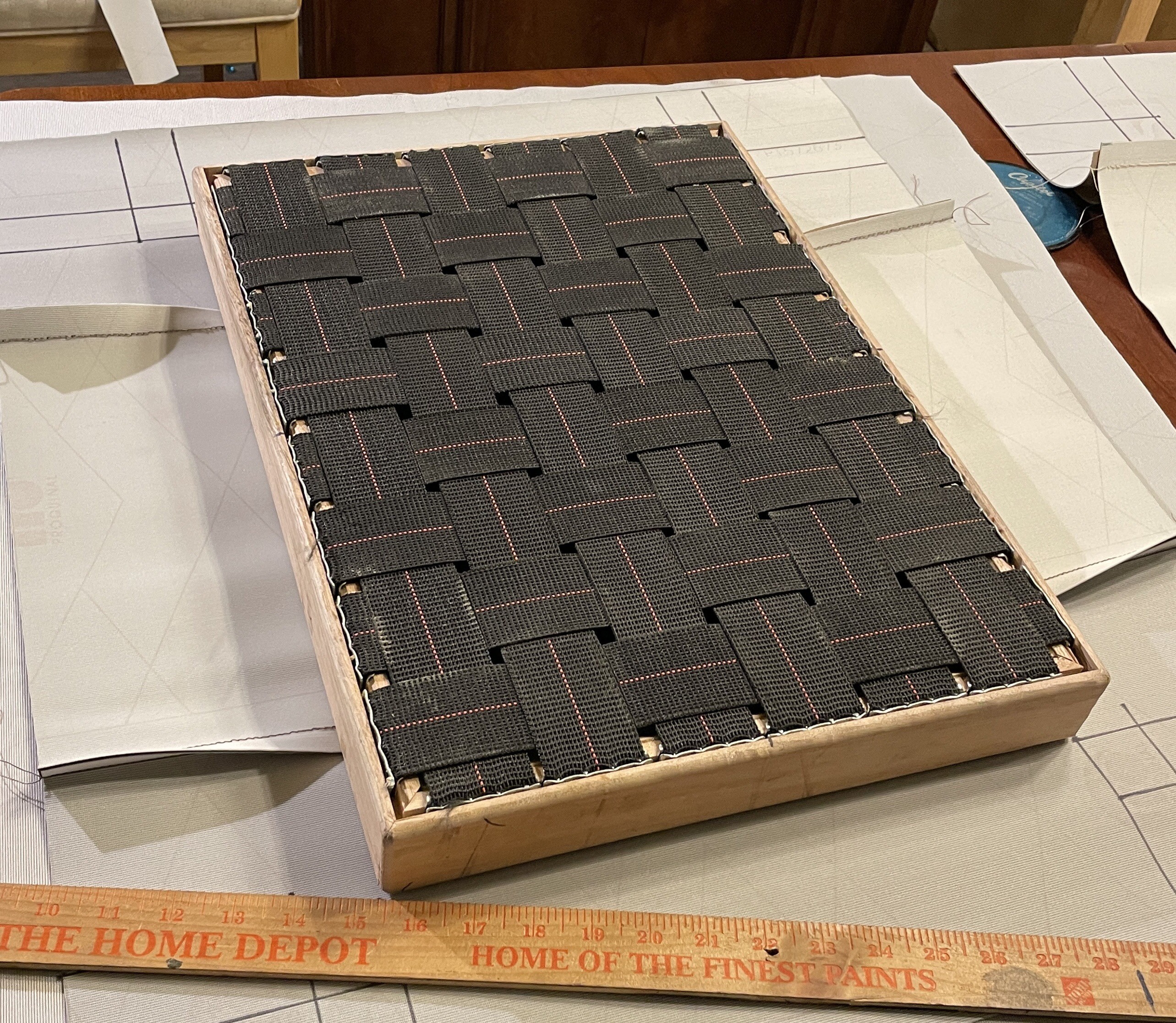
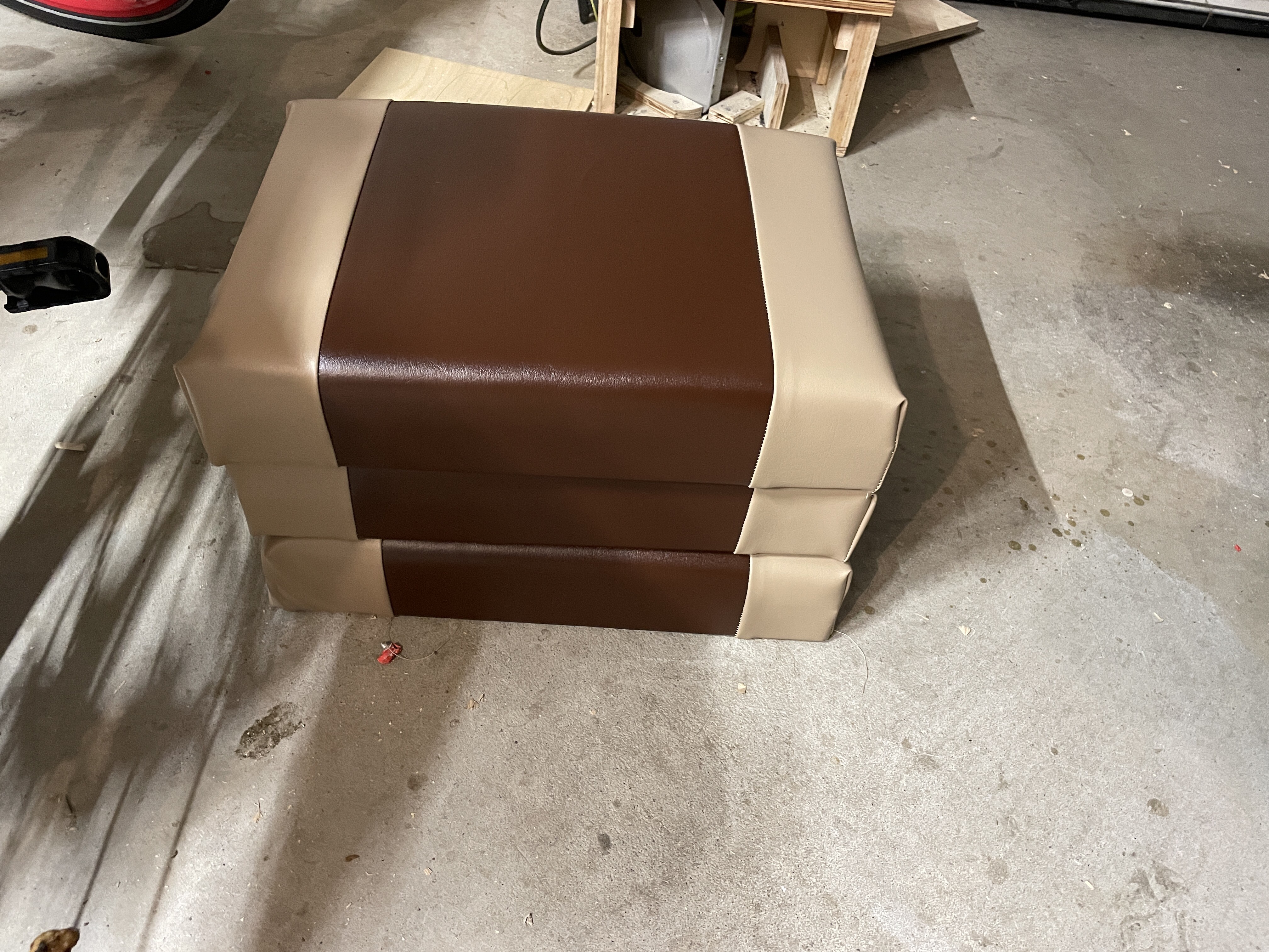
The night before maker Faire the seats were finished as well, some pics below. These are 2” high on the sides, 19x14” width and length, with 2” foam on top of the woven upholstery elastic.
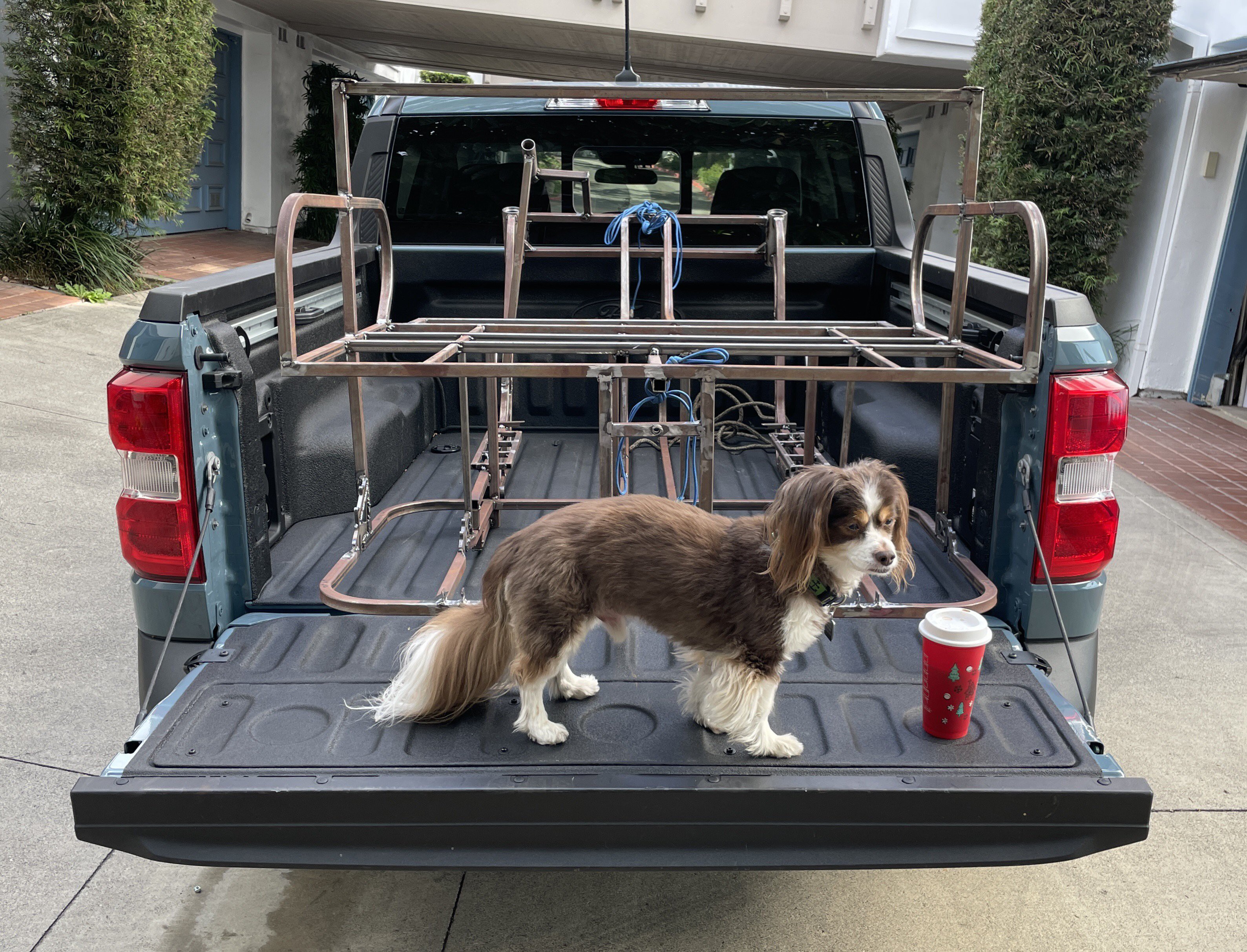
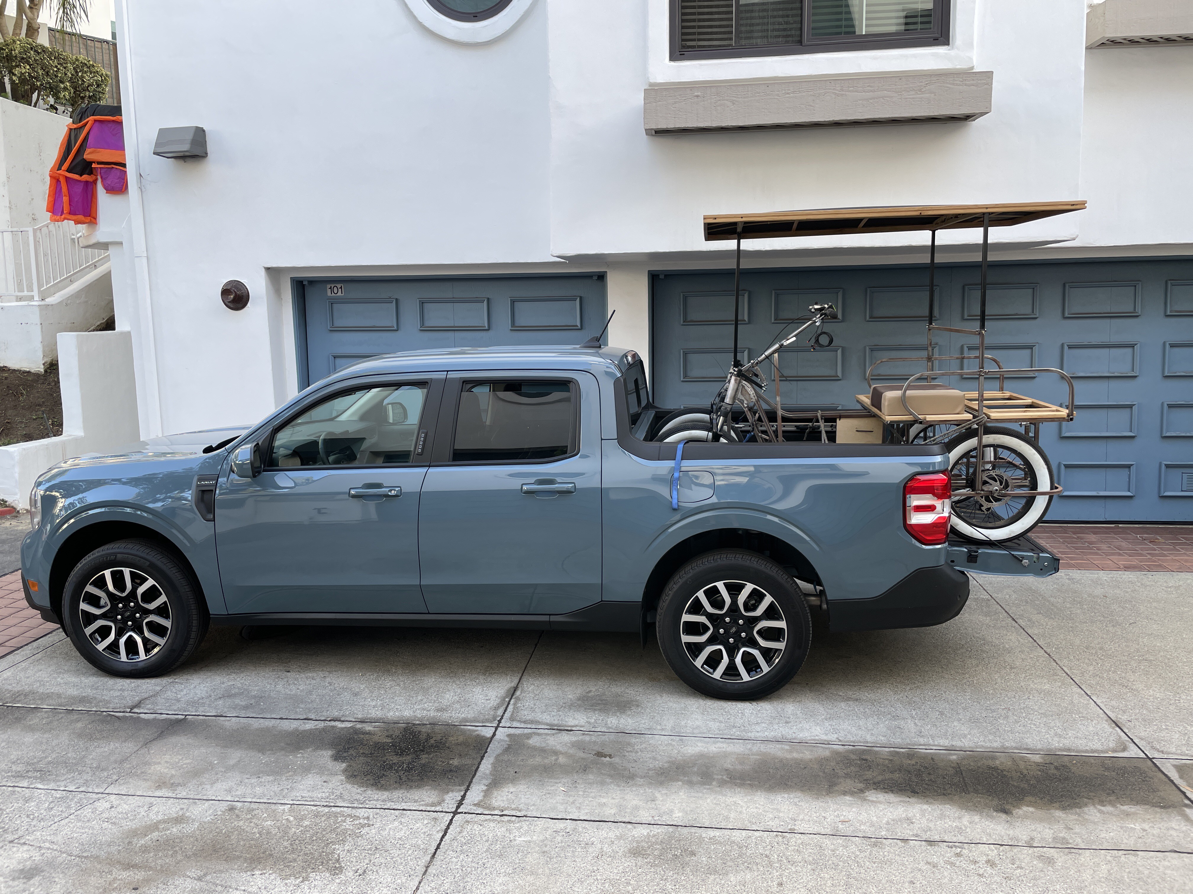
The next day the bike was loaded up!
and here it is at Maker Faire!
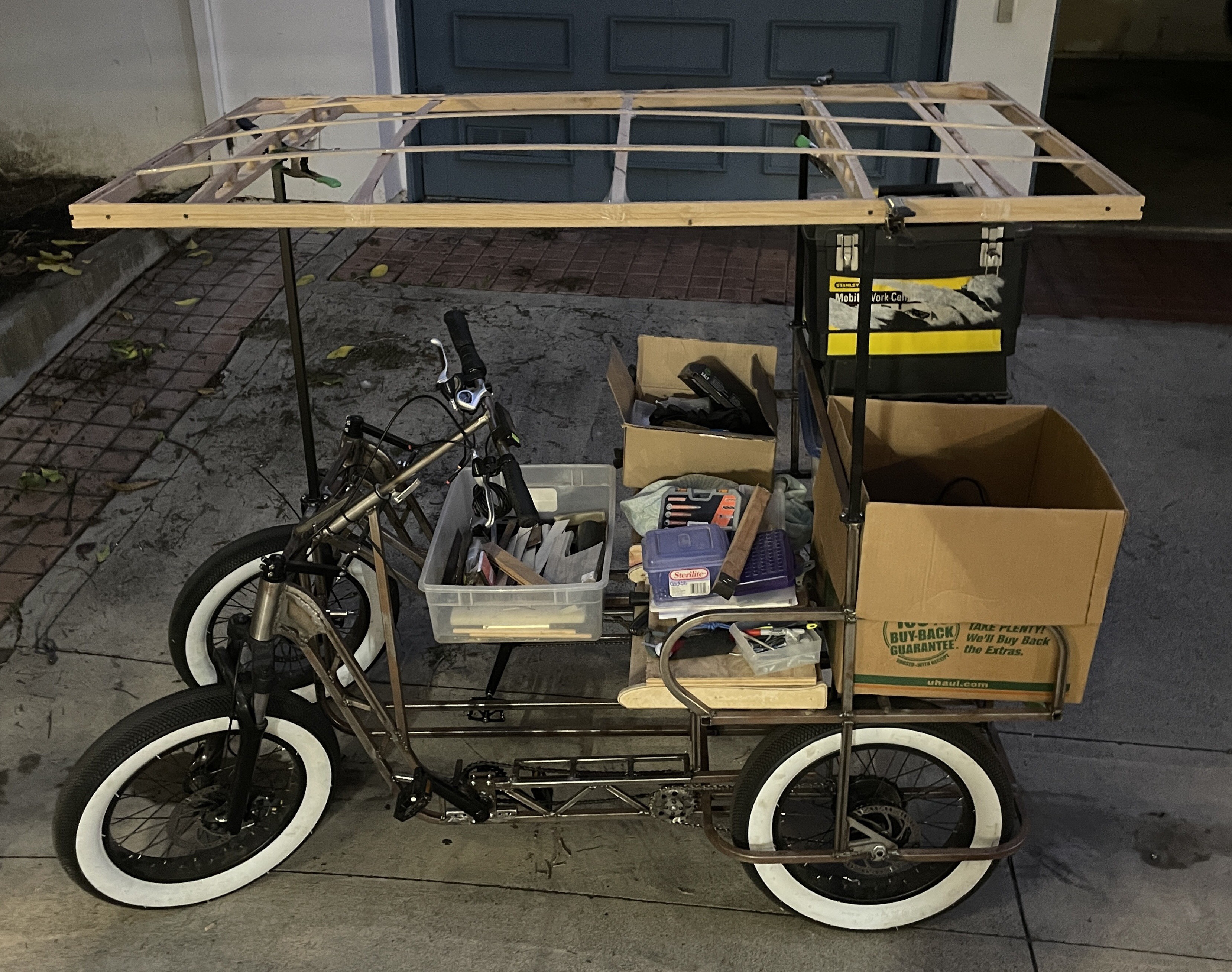
maker Faire OC is this weekend, and Woody will not be complete.. we still plan on going though. In it’s raw state it is easier to see this is a hand built vehicle anyway.
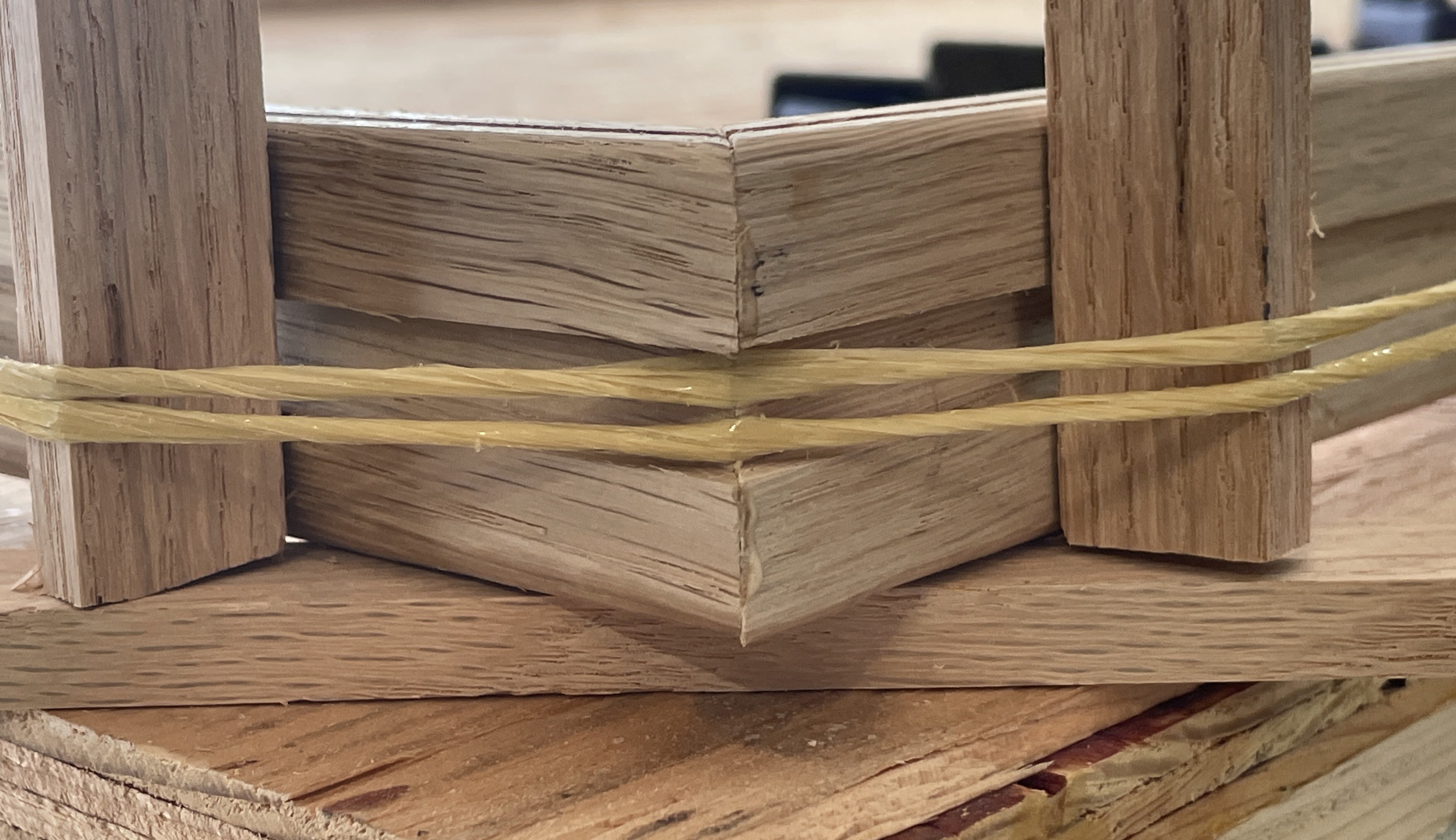
Anyway, to update briefly, tonight the awning was built. The wood used is white oak.
The perimeter is 1.5” tall, and a slight bit over 3/4” deep. The top edge has a rabbet for the bent stringers and a 1/8” dado 0.25” deep for screen spline holding shade cloth. The outside vertical surface has a 0.375x0.125” dado for the programmable light strips.
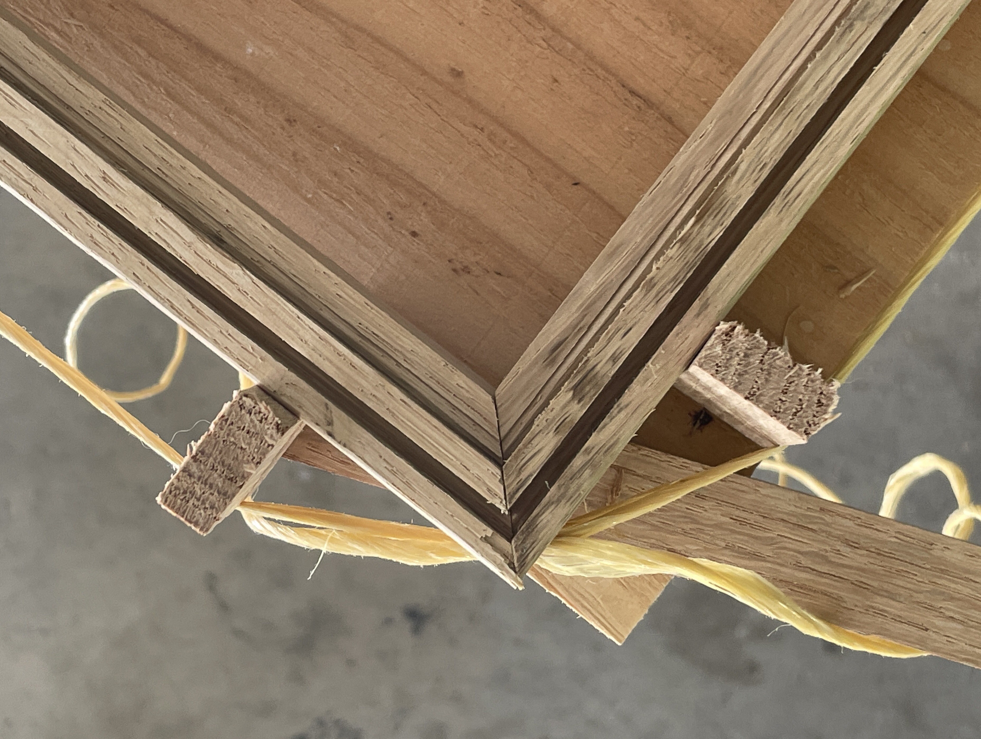 Top view of rabbet and dado. Rabbet was cut will alternating top bevel combination blade, perhaps I should avoid this!
The side view shows the dado for LED strip, as well as the polypropylene twine used to cinch the frame together. The led dado was made on a router table.
7
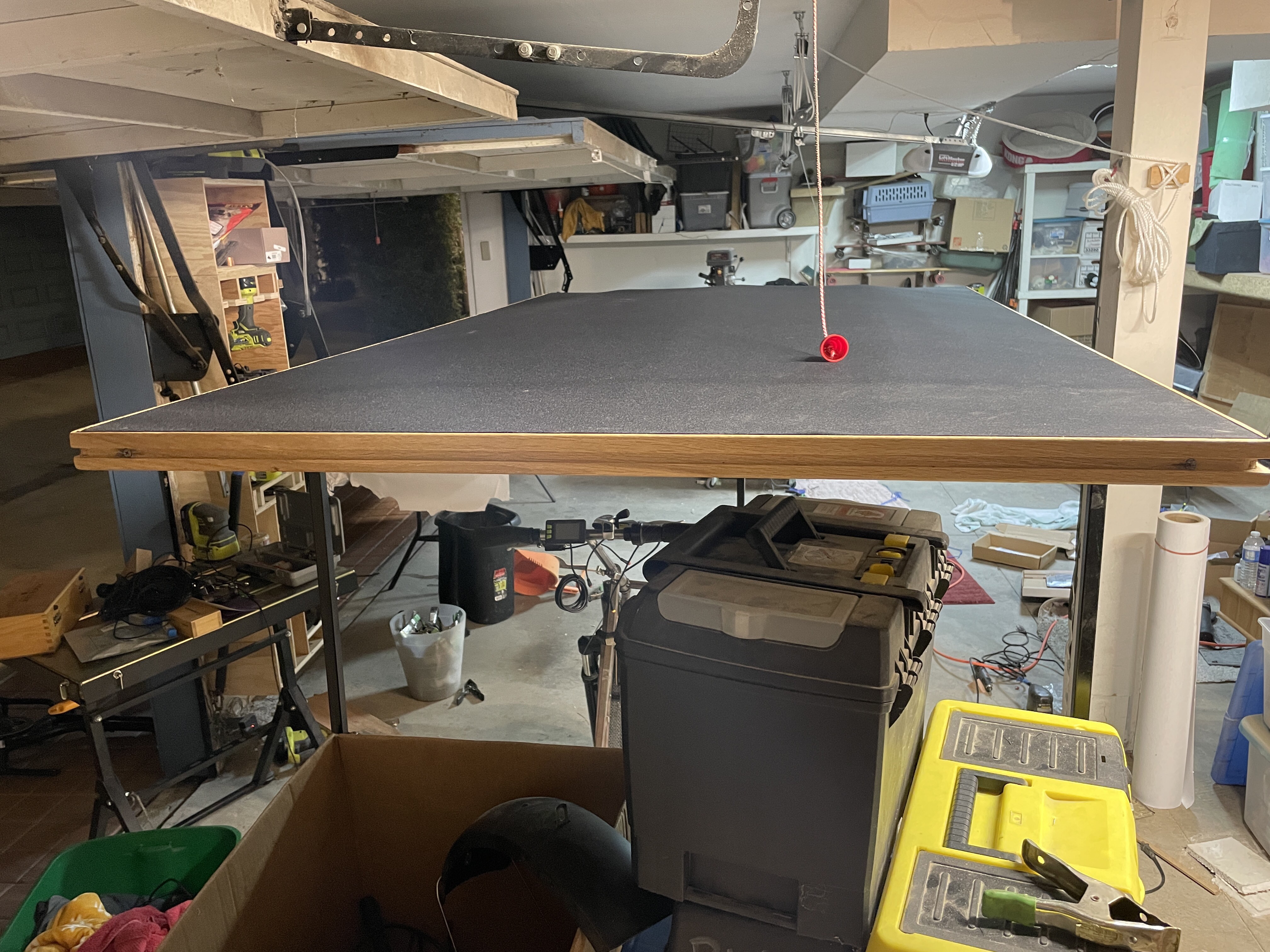
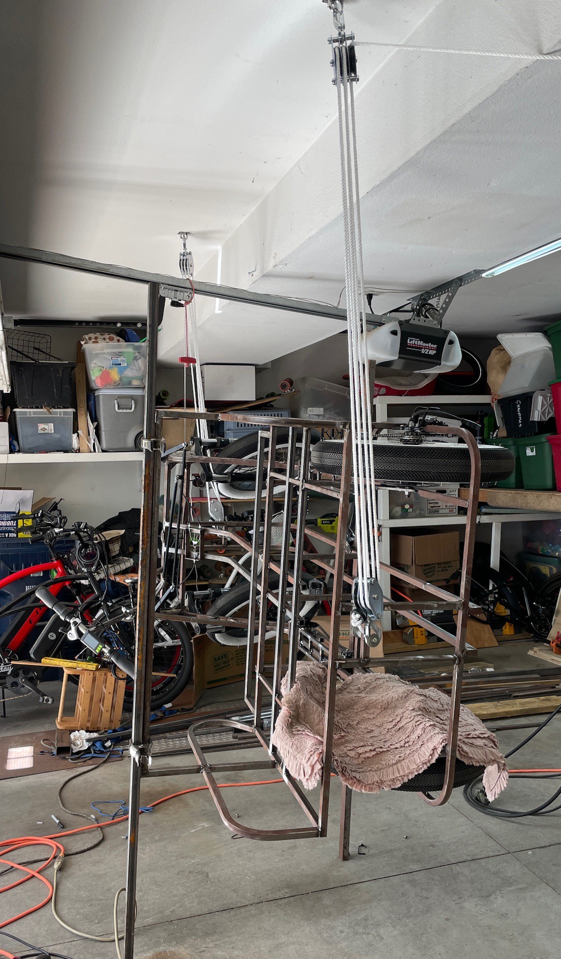
This weekend was spent mostly welding. First though, I needed to get to the bottom of the bike. I bought a pair of pulleys and rope. I thought I was getting nylon rope, but it is poly propylene. Oh well.
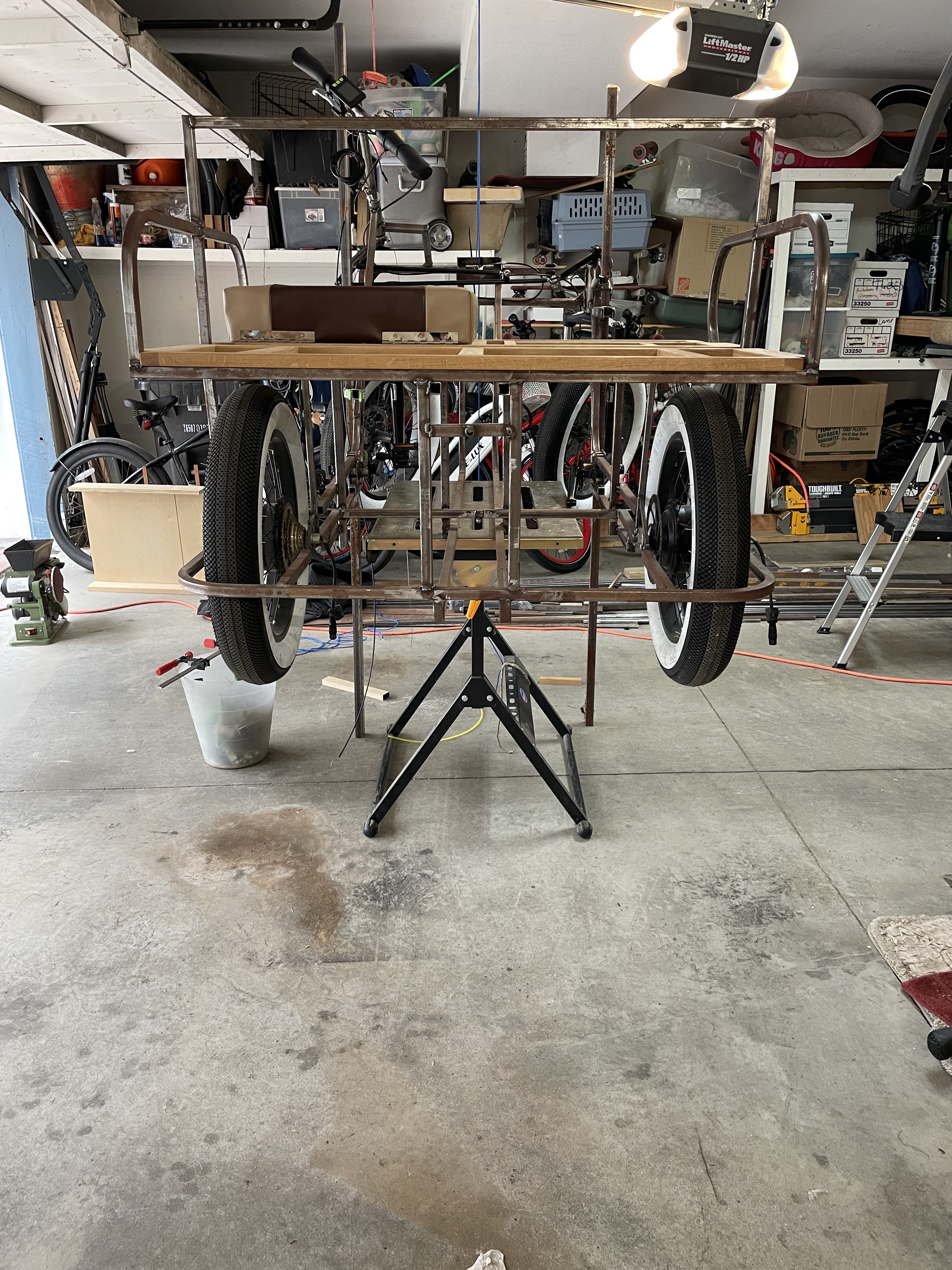
A pair of cleats attached to the ceiling allow me to raise the bike to a comfortable working height. In below picture, the bike is also rotated about 90°. Note in this picture along square tube is clamped to the frame at the seat top to hold the bike in this position. There's also an old rug covering the lower wheel to prevent sparks and dust from messing with tire, chain, and derailleur.
Next up the structure for mounting the running boards was cut, welded together, then to the frame. The front sprocket is about 1/16" proud of the top surface, s a bit of the wood running board will be hogged out here.
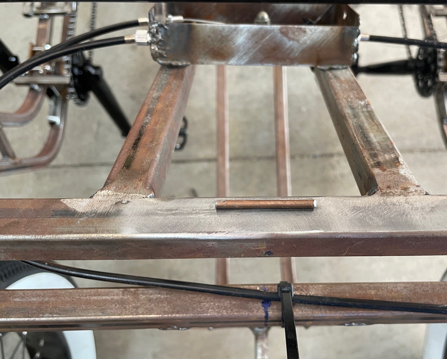
I tried something and I guess it worked, but don't try this without ventilation for sure. I wanted to weld a plate which needed to be flat horizontally, but the tube to which it is welded is inclined about 10°. So I cut a bit of welding rod and used CYA glue (cyanoacrylate, or Crazy Glue) to hold it in place while the plate was welded. I definitely could smell the glue burning as the tubes heated up.
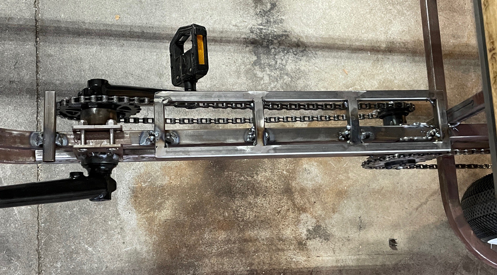
Perhaps a kinder/gentler was of doing this is to use masking tape. Below are the zig zag 1/2" square tubes used to reinforce the two 3/4" main tubes. It ends up masking tape worked well here, and did not catch on fire provided I used a small tack weld. Also on the very right edge of the picture a rusty piece of tubing is clamped to the frame to prevent swinging on the pulley ropes.
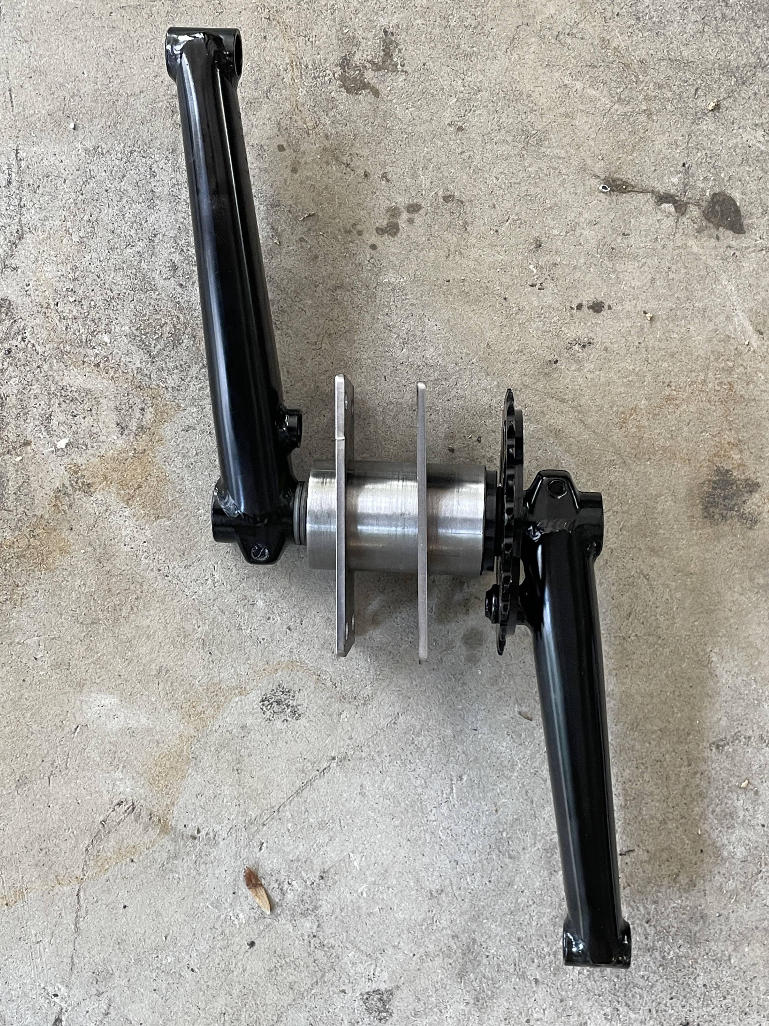
woody is using BMX cranks because they allow very small sprockets. Below is one of two assemblies before welding. The bottom bracket was turned on the lathe, and the two plates were made by sendcutsend.
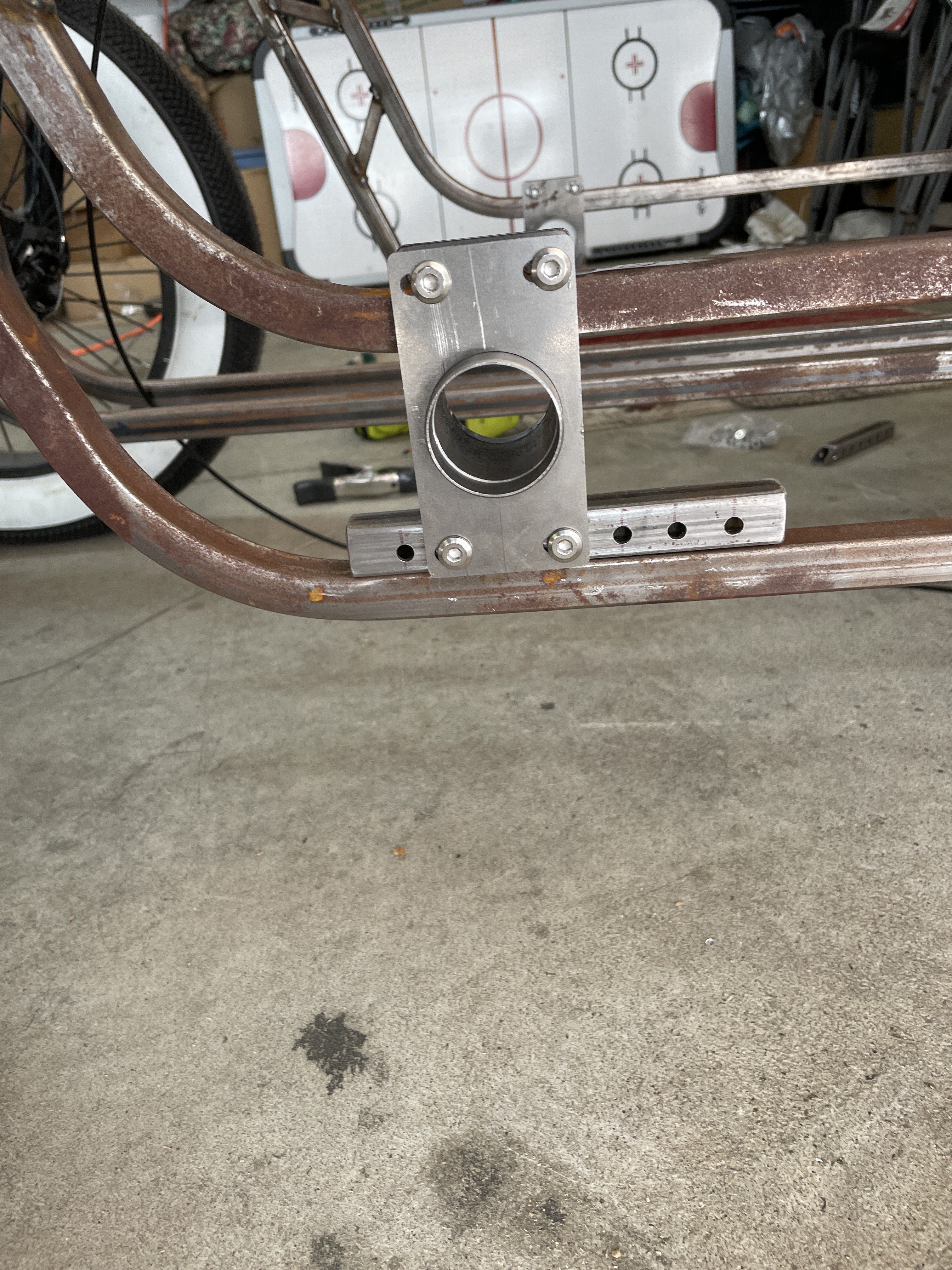
And here it is bolted in place. The holes are slightly more than 0.75” long to allow chain tensioning. The lower piece was added to help raise the crank height a bit.
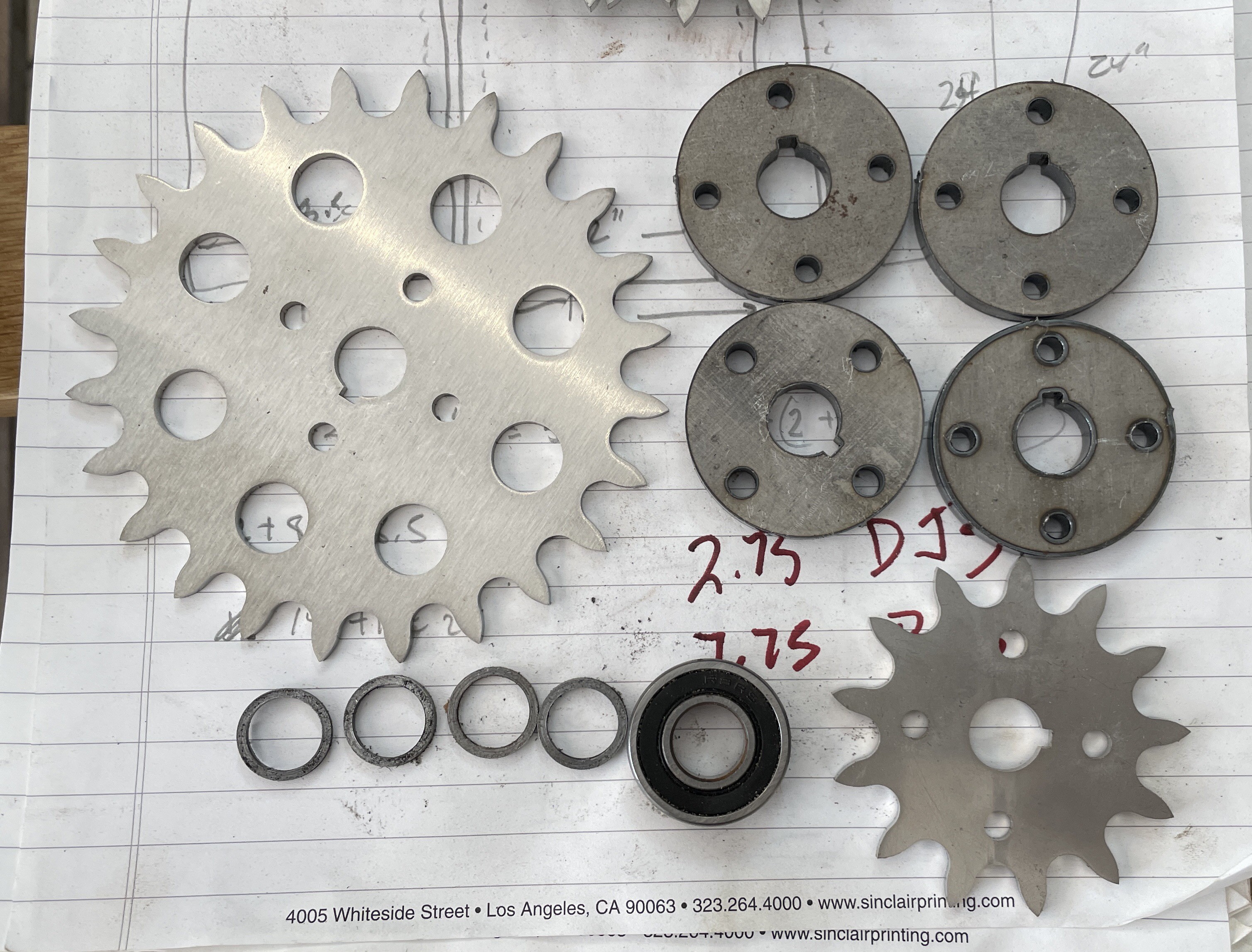
These are the sprockets, bearings, sprocket flanges as well as some small washers cut on the lathe to prevent rubbing against the bearing seals.
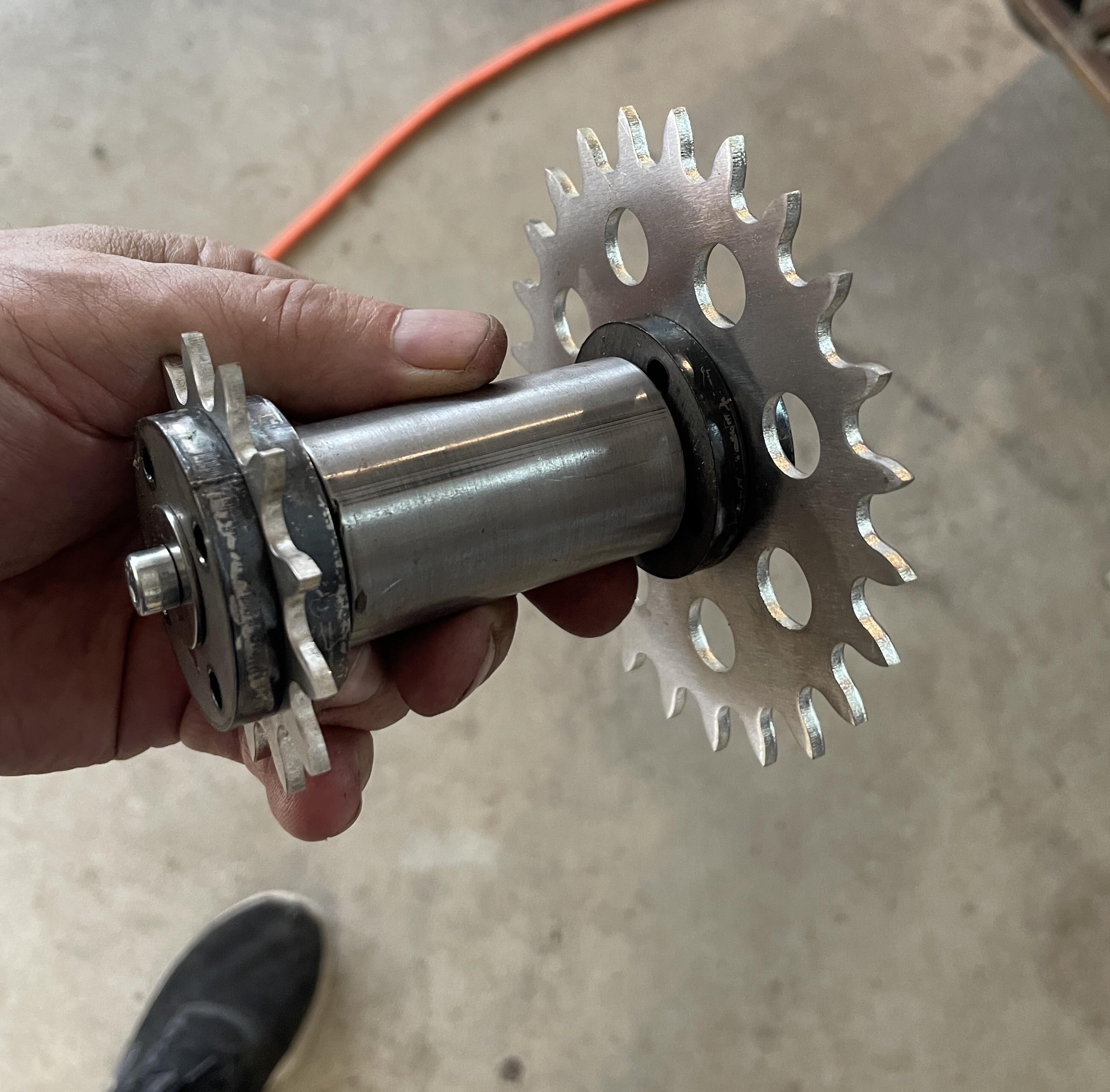
And this is what an assembled Jack shaft looks like. Note two different gear sizes, this gives a gain of two across the Jack shaft, allowing the front sprocket to be half its normal diameter and yet still get a useful gear range.
The whole bike was moved up on top of a welding table to make it easier to install components.
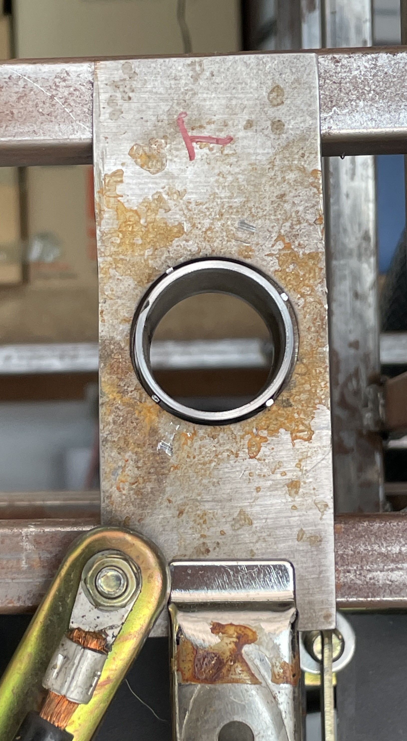
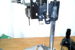
Making 1.25” diameter holes in sheet metal was beyond my drill press capabilities so a quick trip to Harbor Freight and I bought a chassis punch set. However, 1 1/4 conduit is a bit bigger than 1.25” OD tubing. So I hammered a bit of steel wire thinner to shim the tubing into the hole.
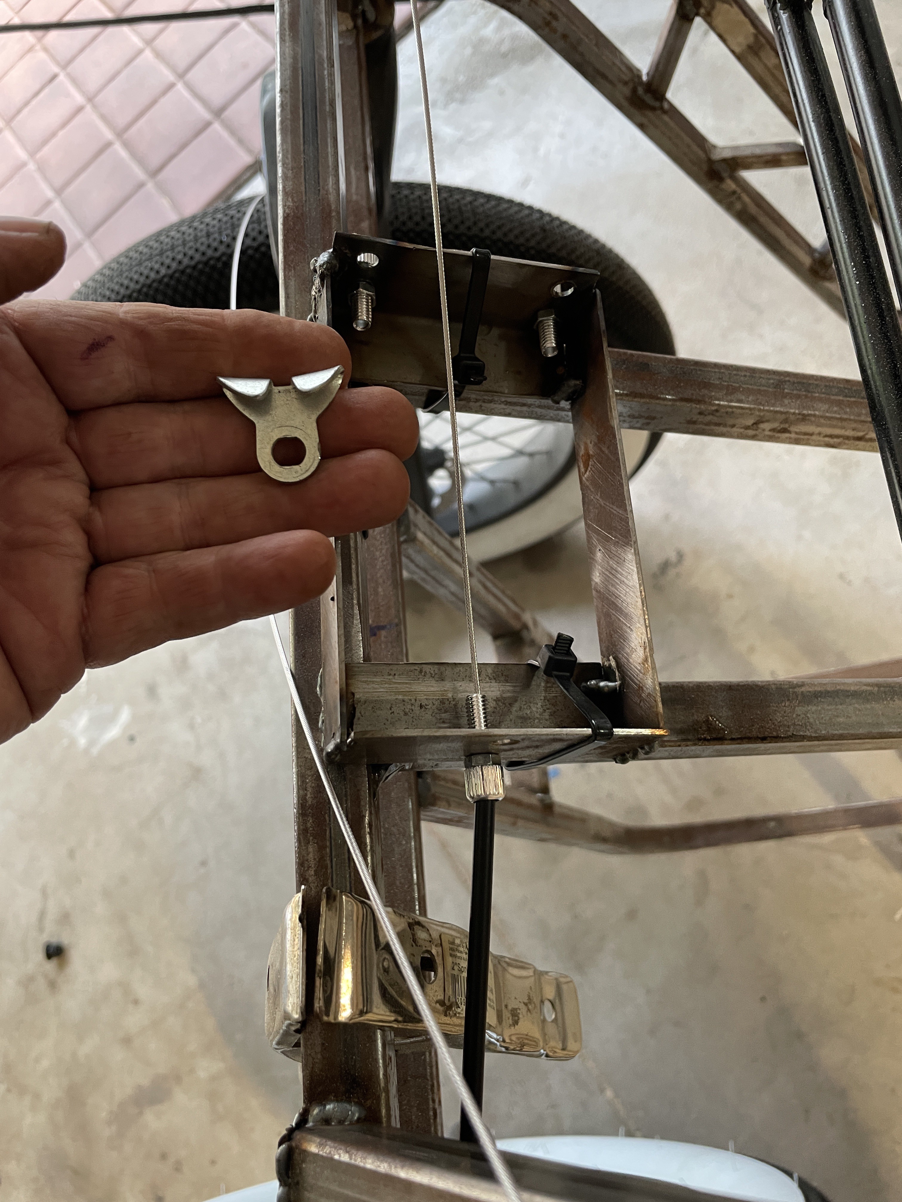
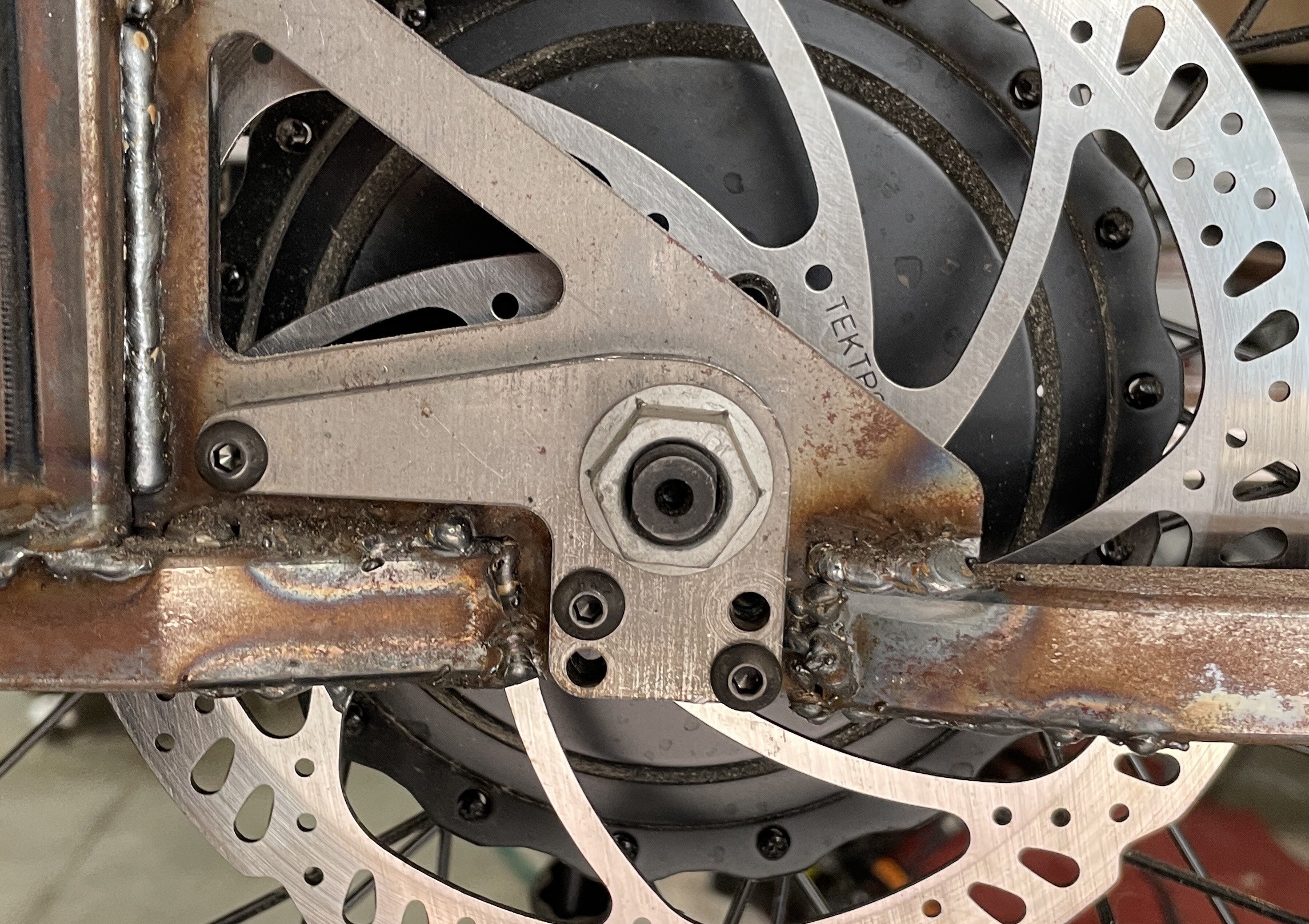 With bike elevated I tackled an easy task, installing the torque arm. Evidently I designed for socket head screws but bought button head. This two screws are missing. The torque arm contact the two flat sides of the axle, allowing torque from the motor to transfer to the frame without the axle spinning.
previously the steering column was 0.5” tube, sealed ball bearings, and a 1.25” OD as a housing. I worried that the 0.5” tube, extended about 11” to the handlebar, could easily bend or break.
Using the same seats for the ball bearings are new plastic bushings made from acetyl copolymer. Not as slippery as ptfe, and not as soft as UHMW, it turned on the lathe quite easily. Now the steering tube in 0.75” OD.
one reason to fix and finish the handlebars was this realization: as soon as the pedals, chains and derailleurs are mounted we will want to ride a bit. So handle bars are done, and on to the brakes.
The above box is temporary, it converts each brake handle to two different brakes (remember this is a 4 wheel bicycle).
One may wonder, why is the bike called Woody? Well, it was always intended to have significant wood trim. Today saw the first pieces built.
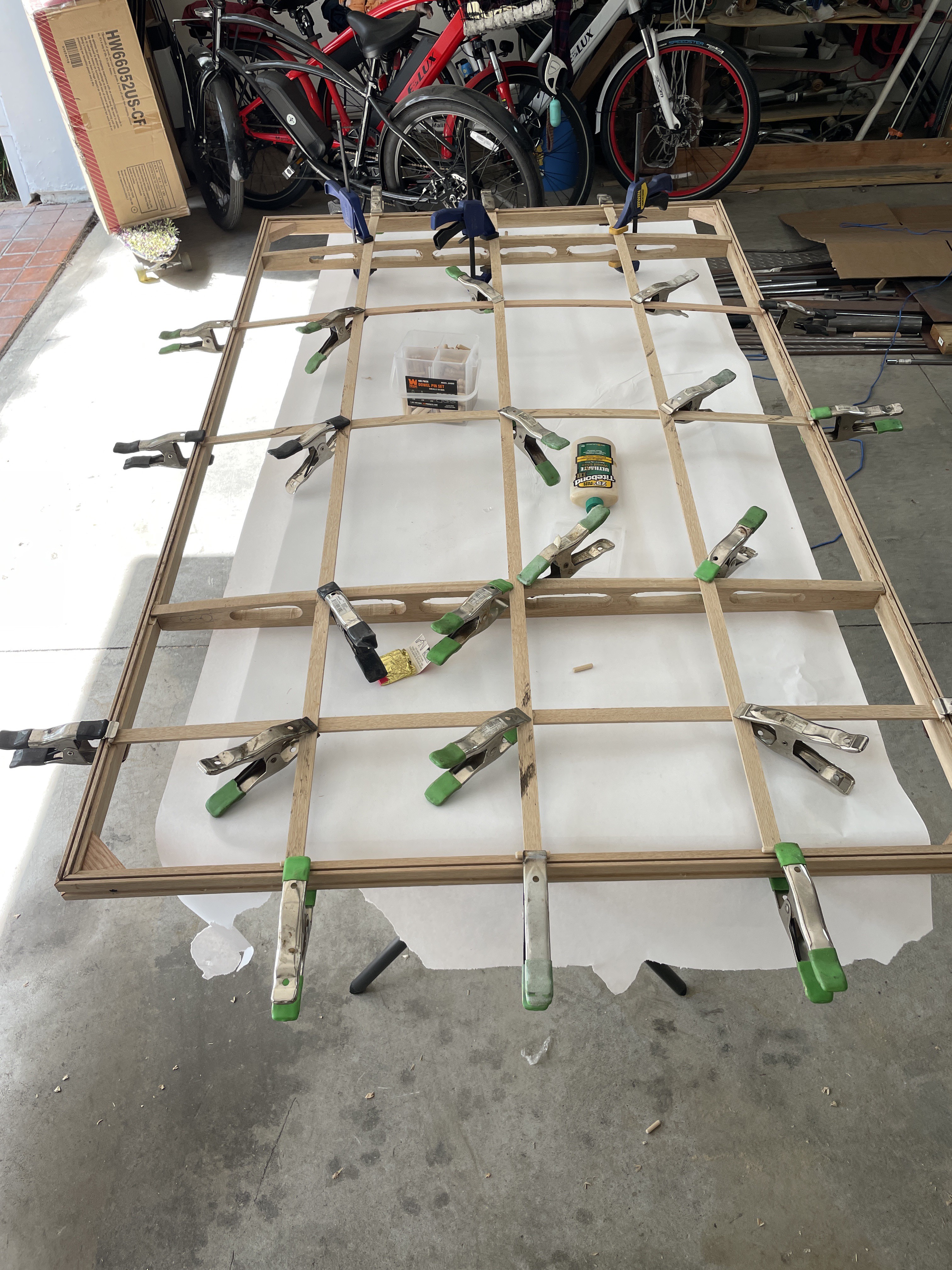
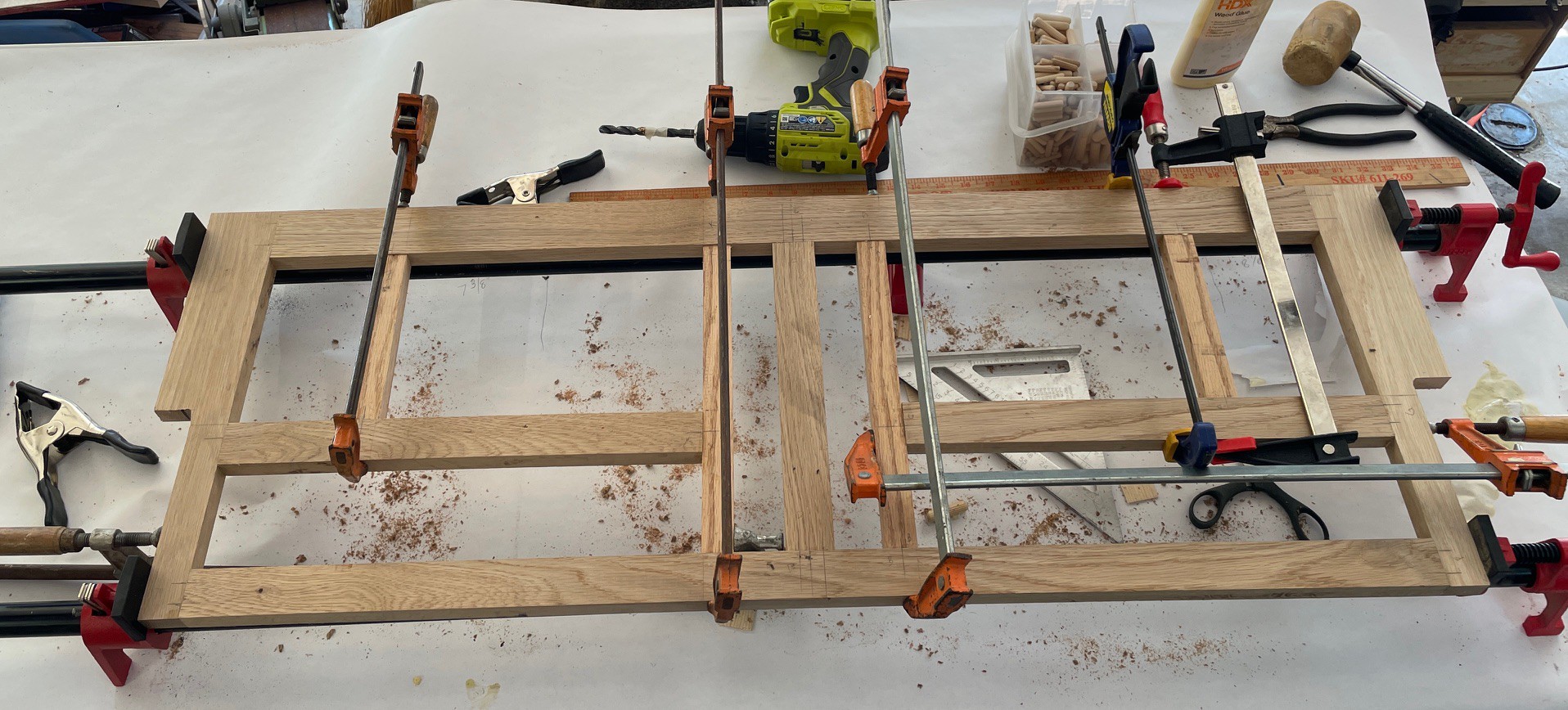
This is the front seat frame. The various rails are for alignment to the frame, and form the edges of storage bags. This is white oak, given to me by the illustrious Jack W. The joints each have one or two 3/8" hardwood dowels for alignment and strength.
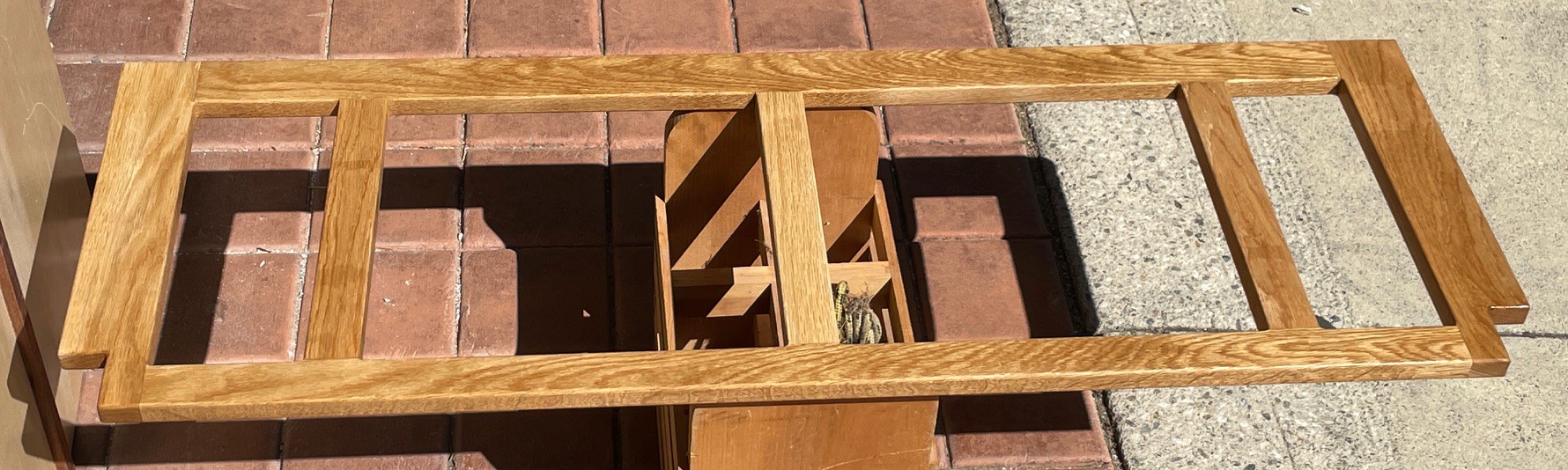
This is the rear seat frame. It is much simpler in design as there is less going on in metal behind the rear wheels. This is one coat of Gloss acrylic spray, the Rust-o-leum 2X brand. This dries to the touch in about 20 minutes, especially when left in the sun as below.
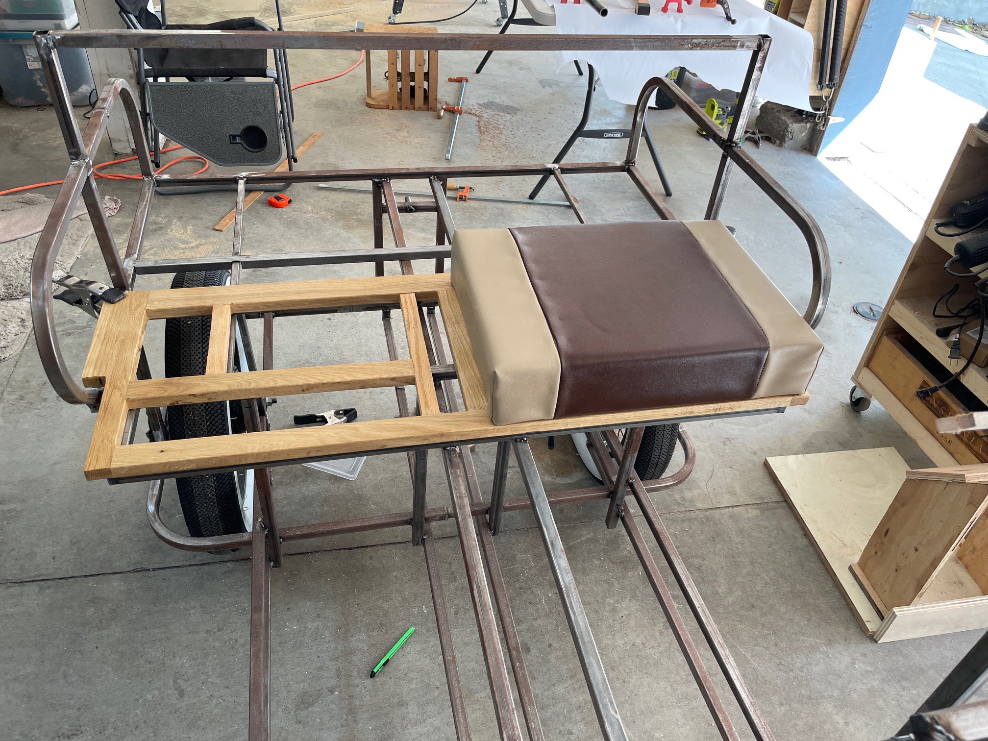
And here is the front seat frame on the bike, with the one seat which has been completed.
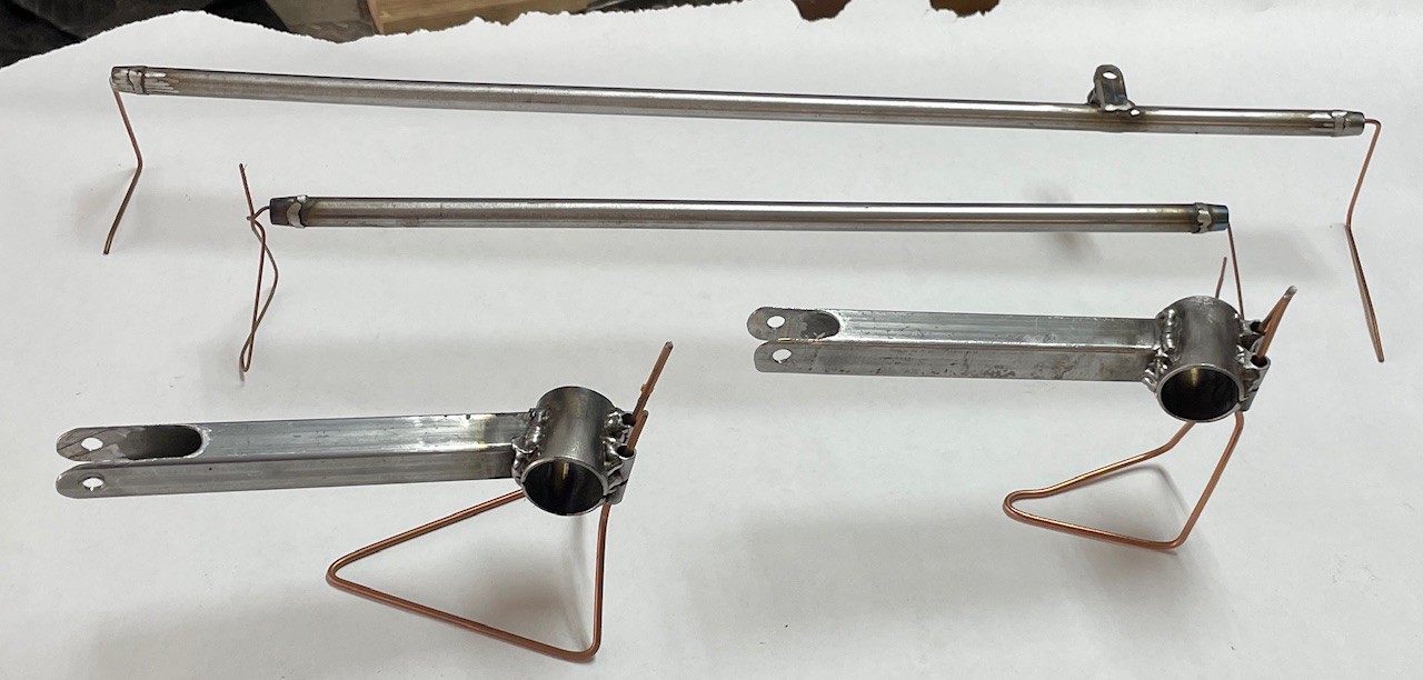
While the intention is to get the main frame powder coated, there are still miscellaneous small parts which be painted with rattle can, Rust-o-leum Semi Gloss Black.
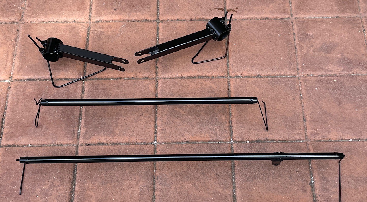
These are the two steering arms, the tie rod, and connection from the middle of the tie rod to the steering column. A few bits of welding rod are put to good purpose here.
After painting they are moved outside to get a bit of UV light bleeding through the overcast this morning. They were left to dry about 4 hours.
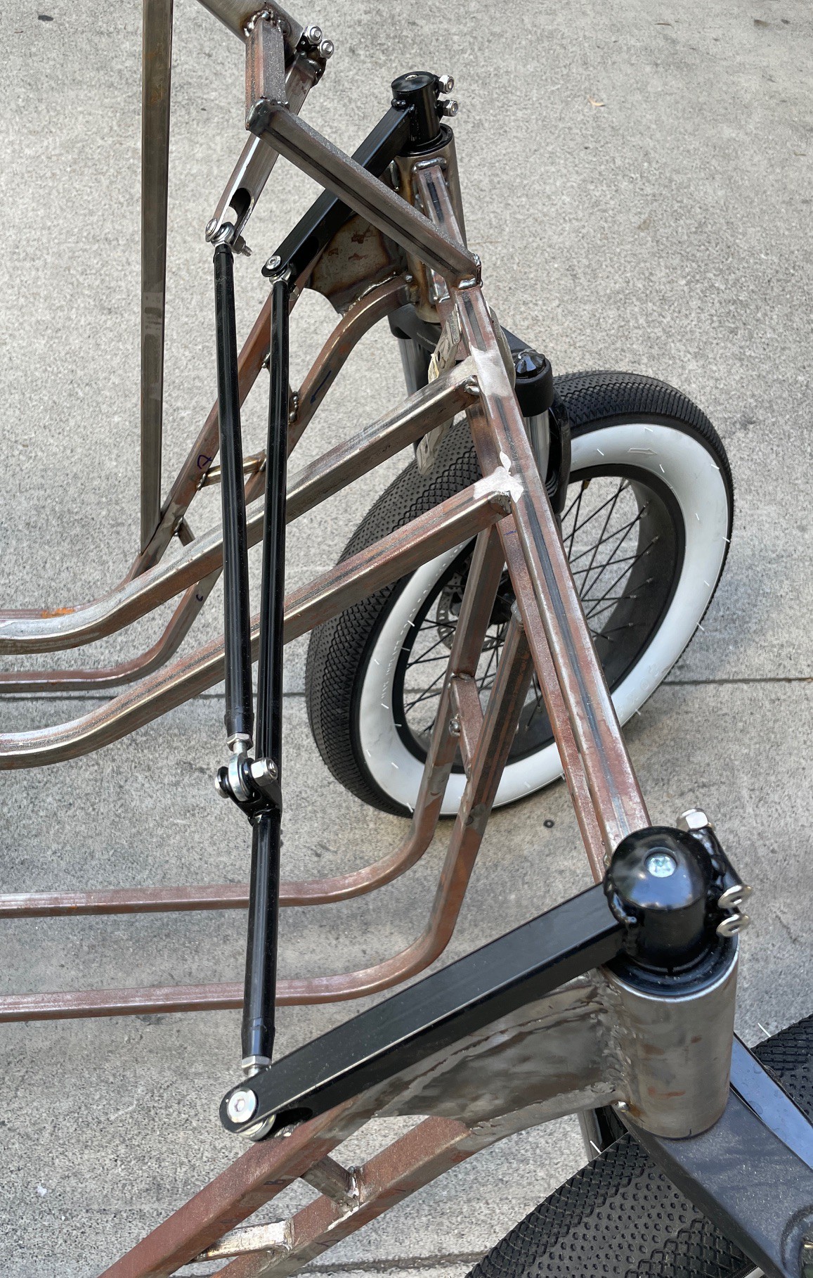
And here they are installed! Note the steering column hardware was not painted, this will be modified.

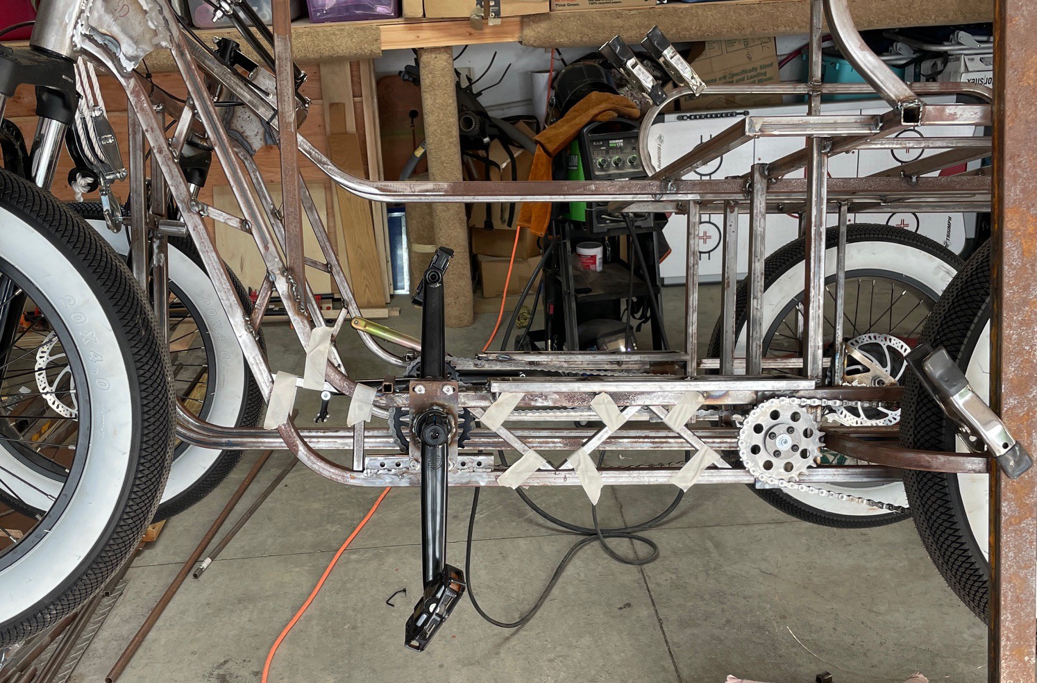
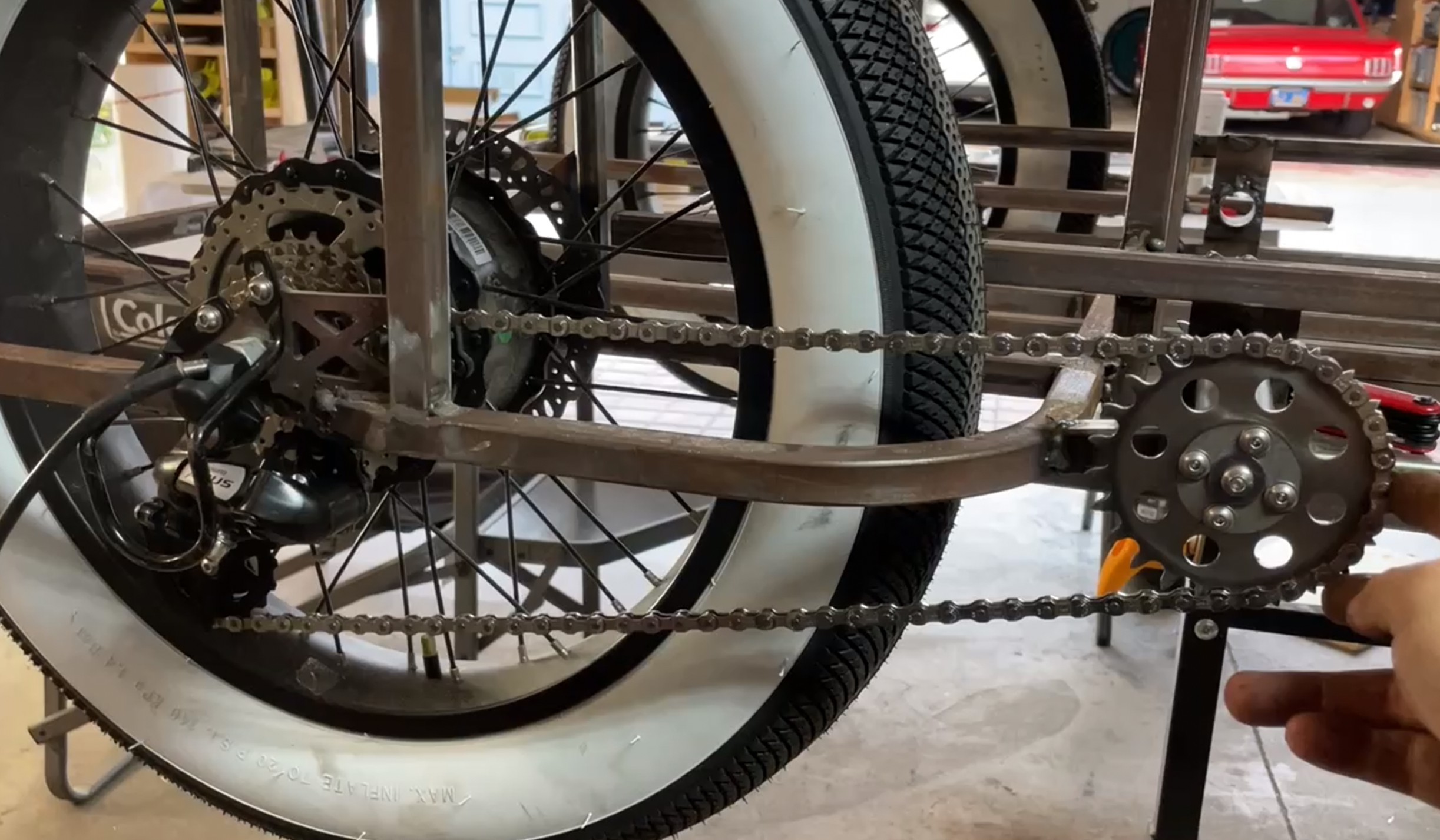 And here is a Jack shaft installed, with a chain to the derailleur. But the front chain needs to be 1/8 wide, not multispeed like the rear, so I need to buy a couple BMX chains. Also, the 0.1” stainless sprocket was a bit too thick for the 7 speed chain, and had to be ground down extensively.
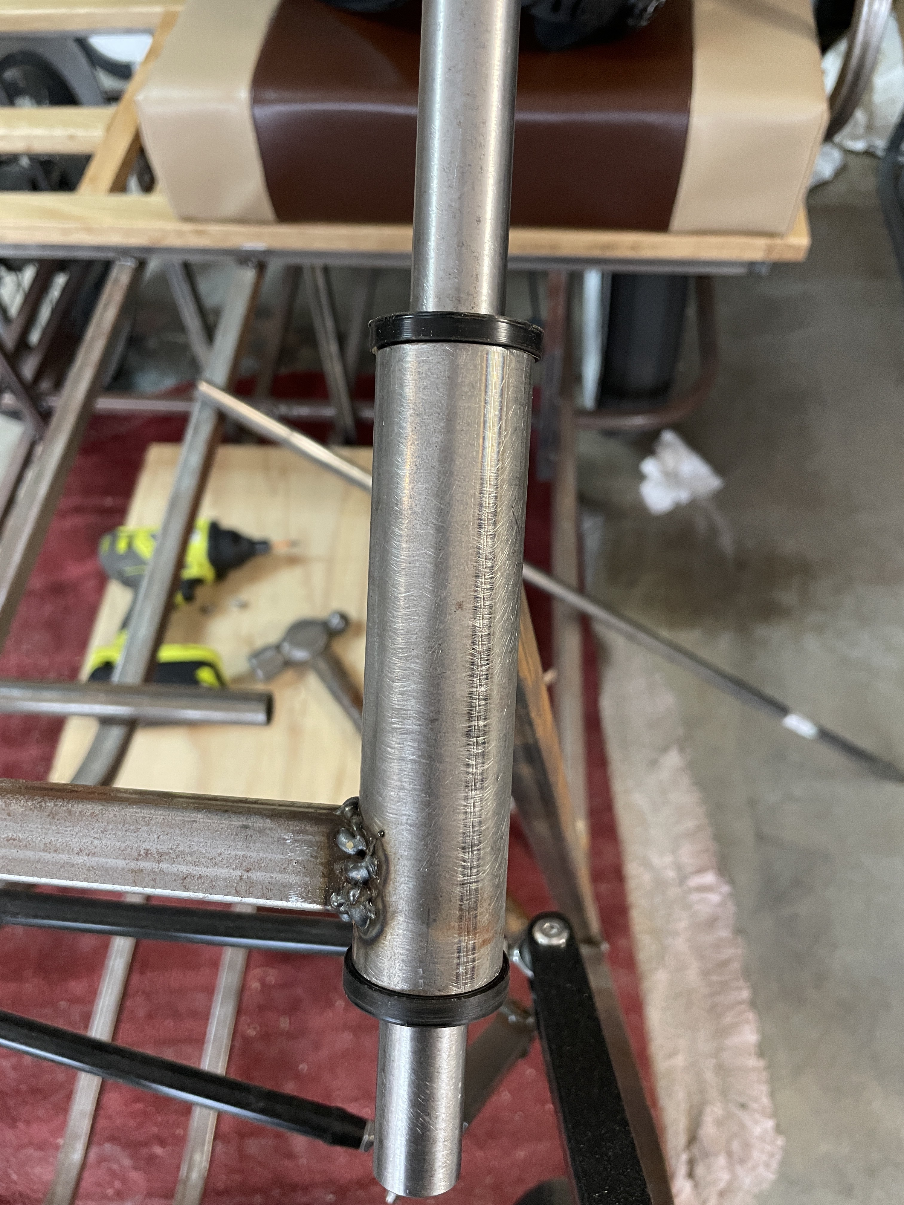
 sebwiers
 Eric Hertz