Close
0%
0%

DIY $8 Mechanical Numpad

DIY $8 Mechanical Numpad (with Arduino Compatible Firmware!) and how I optimize it for international shipping

Similar projects worth following
A few months ago, I developed and open source the 4xMacropad, a $3 macropad made using CH552G. After seeing much of the feedback from the internet, I notice I can better utilize this chip to make a keyboard with more keys. That is why I am trying to make a numpad in order to use 100% potential of this particular chip.

There are lots of good looking mechanical numpad out there with cool designs. But most of them falls into the 40 - 50 USD range (for DIY kits). That is why when I am deciding this numpad, my goal is to make it as cheap as possible, while maintain the good features from the previous builds:

Arduino Programmable
Cheap and easy to make
Little to no change in BOM list


After a few weeks of trial and error, I finally get a numpad made with the identical BOM list (actually this numpad has less SMT parts than the pervious 4xMacropad build) and successfully make it cost under $10!

Why I made this

A few months ago, I developed and open source the 4xMacropad, a $3 macropad made using CH552G. After seeing much of the feedback from the internet, I notice I can better utilize this chip to make a keyboard with more keys. That is why I am trying to make a numpad in order to use 100% potential of this particular chip.

There are lots of good looking mechanical numpad out there with cool designs. But most of them falls into the 40 - 50 USD range (for DIY kits). That is why when I am deciding this numpad, my goal is to make it as cheap as possible, while maintain the good features from the previous builds:

  • Arduino Programmable
  • Cheap and easy to make
  • Little to no change in BOM list

While improving some designs that was most commented agaist

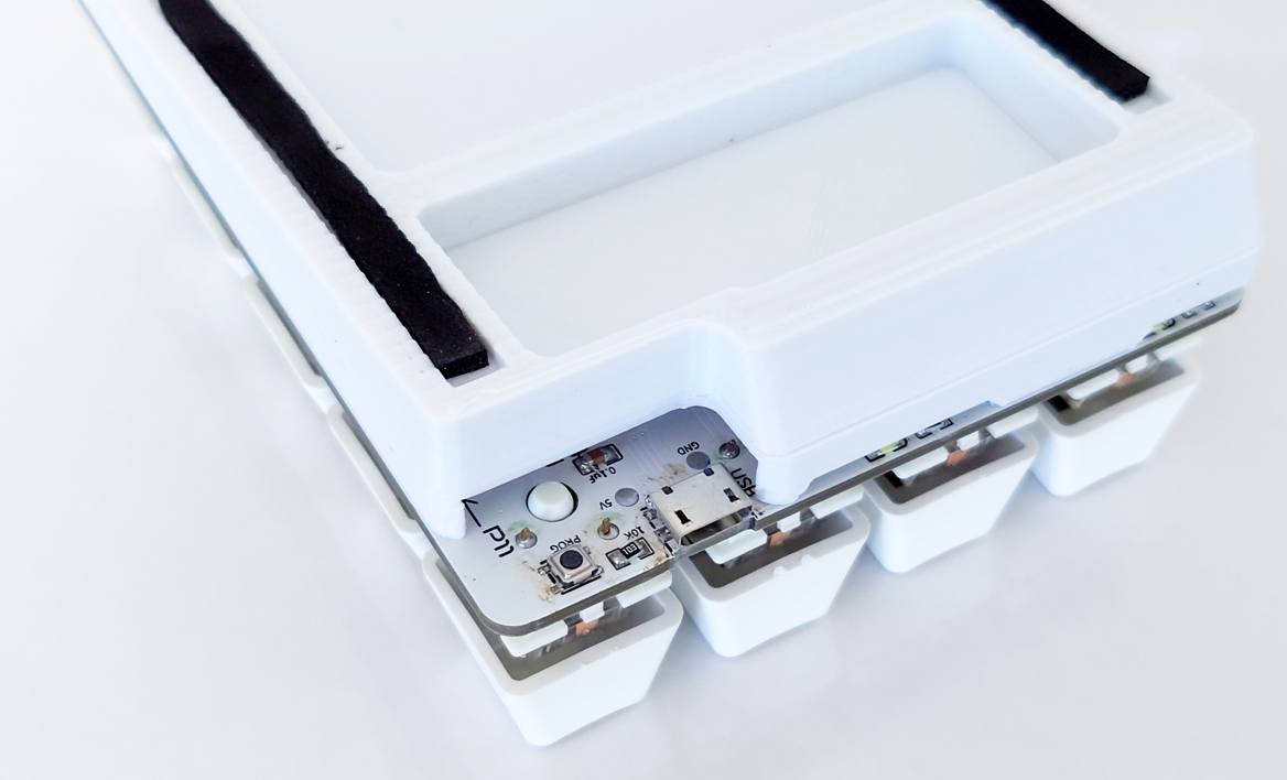
  • Swap out the mini USB port

After a few weeks of trial and error, I finally get a numpad made with the identical BOM list (actually this numpad has less SMT parts than the pervious 4xMacropad build) and successfully make it cost under $10 USD.

How this design turns out to be bad for international shipping (and for sale)

If you are also an Instructable reader, you will notice this post is slightly different than the one I wrote on Instructable. The reason is I do not have enough confident in shipping them out if I put it on hackaday (and Tindie). I have make a few sales on Tindie, but I lose money on both of the keyboard I sold. That is because of the design is not optimized for international shipping.

You see, international shipping have strict limits on size and weight of an item. And shipping the original design via parcel will cost much more than the keyboard itself, making it cannot compete with other options on the market.

In summary, international shipping prefer sizes around 15 - 20cm x 9 - 12cm with height around 4 - 6cm. You can wrap it in cardboard box or paper parcel, it doesn't really matters. Only if I optimized the macropad to the required size, I can easily ship it to Europe (from Asia) for less than 3 USD (for the slowest shipping method) or less than 5 USD to the US (also the slowest shipping method).

How I solve the international shipping issue with engineering

Eventually, I solved this be reducing the weight of the numpad to < 500g with some optimized 3D printed parts and wrapping materials.

Old design, which use a two parts construction

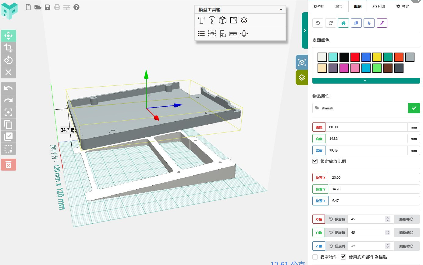
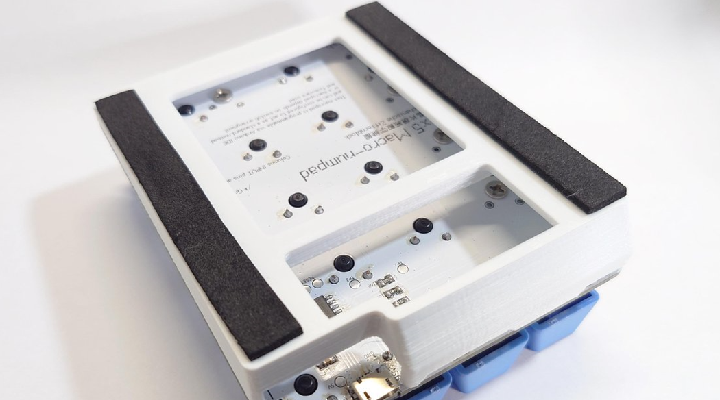
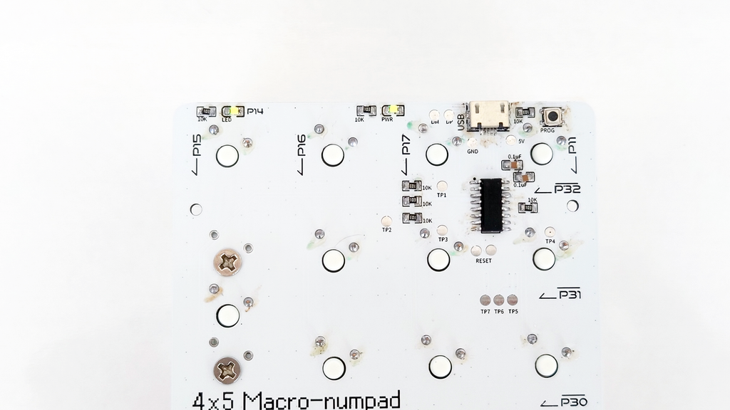
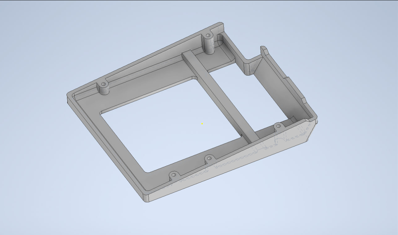
New design, which save much more materials (and weight) in shipping

After the base design is optimized, not even you can see through the bottom PCB which makes it much cooler (new vs old)

I also swapped out the foam case (which is a really nice fake leather container that I ordered from a case maker, but this add too much weight to the parcel) to a standard international shipping Y5 cardboard box.


These changes allows me to reduce the price of each units from 30+ USD to 23+ USD each (because of the shipping cost). Now this is finally ready to be put on hackaday and see how people reacts to the optimized design :D

3d models.zip

3D models for the base, with pre-shipping optimized one and international shipping optimized one

x-zip-compressed - 1.45 MB - 09/07/2023 at 05:21

Download

4x5numpad arduino firmware.zip

Arduino firmware for 17 / 20 keys arrangement

x-zip-compressed - 33.16 kB - 09/07/2023 at 05:21

Download

Gerber_Maco-Numpad.zip

Gerber file for the PCB

x-zip-compressed - 125.74 kB - 09/07/2023 at 05:21

Download

  • 2 × 0805 LED
  • 2 × 0805 0.1uF
  • 7 × 0805 10kΩ
  • 1 × Micro-USB port
  • 1 × SMT Button

View all 9 components

  • 1
    Send the PCB to Print

    The PCB is the main component of the build. So the first thing you want to do is send the PCB to print. Some manufacturer provide free printing services of 1 board per month. If you have a chance to get such promotion discount, you can get a PCB for nearly free of charge.

    You can get the PCB Gerber file here

    https://github.com/tobychui/4xMacropad/tree/main/4x5Macro-Numpad/PCB

    I am printing mine in white just to match my 3D printing filament and keycaps.

    Send the PCB to Print

  • 2
    3D Printing the Body

    The numpad base is compose of two parts. The first part is the part that cover the back of the PCB. The other part is the tilting platform that the base plate is mounted on. You can edit this part to adjust to fit your primary keyboard tilting angle or just not using it at all if you prefer your numpad to lie completely flat on your tabletop.

    You can get the 3D model files here or with the links below (or see the project file section)

    https://github.com/tobychui/4xMacropad/tree/main/4x5Macro-Numpad/3D%20Model

    The two pieces are held together using 4 M2x5 screws.

    If you are planning to use the standard numpad arrangement, remember to print the switch stabilizer as well. It help keeps the 2U switches (enter, 0 and +) stable and not moving when you press the switch down.

  • 3
    Populate the PCB

    After the parts that can be out sourced to factories, now it is the hand crafting parts. Follow the diagram above to solder the parts in place. This will allow the MCU to perform a grid scanning on all the switches by activating each row (LOW activated) and read from each column (when the read is LOW, means that active row's reading column button is pressed).

    This diagram showcase the simplified circuit diagram of the PCB, in which the rows are low activated instead of the normal high activated. This design can save 1 10K SMT resistors compare to HIGH activated design, and therefore making the BOM list identical as the previous macropad design.

View all 8 instructions

Enjoy this project?

Share

Discussions

Ale o co chodzi wrote 09/08/2023 at 05:16 point

how fast is this dev?

power is good for mobile dev?

  Are you sure? yes | no

tobychui wrote 09/11/2023 at 07:07 point

You just edit a few lines of Arduino code. And for mobile, I am not sure if it will works or not. At least I tried on my Sony phone it doesn't seems working. But Samsung with dex mode might work I guess? You gonna test it out yourself :P

  Are you sure? yes | no

Similar Projects

Does this project spark your interest?

Become a member to follow this project and never miss any updates