Close
0%
0%

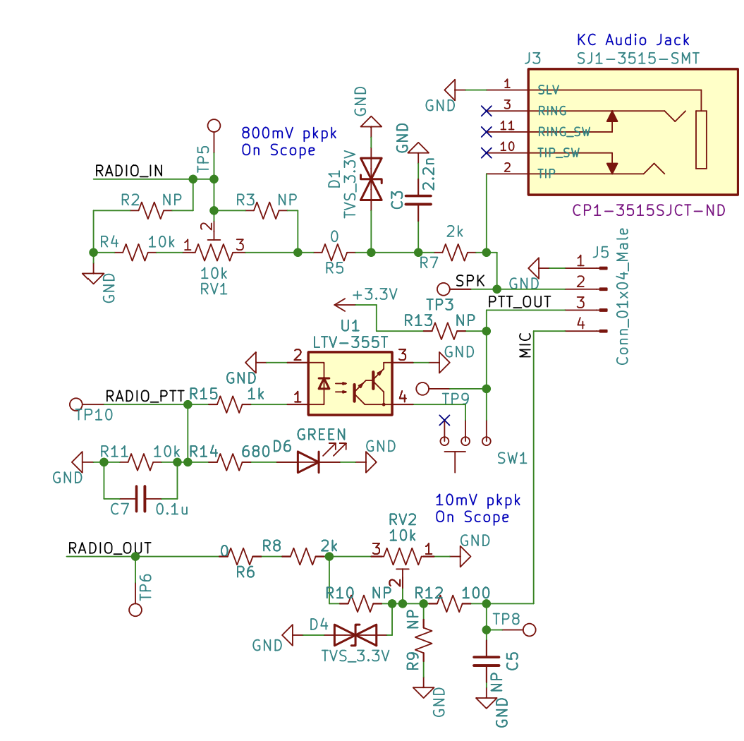
AGC Preamp for Boondock Echo

Non-standard use cases sometimes need special treatment

Similar projects worth following
I've been beta testing for Project Boondock Echo and I'd like to be able to boost the audio signal going into it from my scanner.

Detailed description to follow

  • Impedance Measurements

    Dan Maloney11/09/2023 at 17:51 0 comments

    Seems like I need to know the impedance of the scanner REC output and the dock's aux input. Bearing in mind I have no idea what I'm doing, I turned to Alan Wolke (W2AEW) for help. He's got a load of great videos, one of which explains how to measure -- or at least approximate -- input impedances of unknown circuits with a scope, a function generator, and a variable resistor.

    1. Dock Input Impedance

    Test setup is the same as before: function generator making a 1-kHz sine wave at 60-mVpp into the mic jack of the Baofeng. Transmit into 50-ohm dummy load on 146.420 MHz, scanner receives and pipes it into the 3.5-mm extension cable and into the aux jack on the dock. Scope probe on TP5. I already know that unloaded, the scanner puts out 680 mVpp, so if I adjust the pot on the sidekick board so the signal is half that, that means the resistance from TP5 to ground should equal the input impedance. I got 18k ohm measuring it this way -- seems high given how much the dock seemed to load down the scanner, but whatever.

  • Audio Measurements

    Dan Maloney11/08/2023 at 19:07 0 comments

    1. Direct from scanner

    Signal generator is set to 30 mVpp on 146.420 MHz into a dummy load. Scope is clipped to 3.5-mm extension cable tip and shank, probe on 1:1. Looks like a good solid signal coming out of the scanner around 560 mVpp:

    Boosted signal up to 60 mVpp, scanner out jumped to 680 mVpp:

    2. Sidekick board measurements

    Turns out the schematic I have is for the old version of the sidekick board the one without the aux jack. So it's really TP5 I need to be measuring. Here's 60 mVpp on TP5:

    The sidekick appears to be loading down the scanner output quite a bit. Also of note, that's with the gain trimmer all the way CW. If I turn it back to about midrange, i.e., where it's supposed to be, it's only around 230 mVpp.

    3. Baofeng vs. Scanner

    Turns out not to make any sense to do this -- the Baofeng's output into the dock is variable with the volume control, so you can drive whatever the input is to the 800 mVpp target.

  • A Fabricobbled Signal Generator

    Dan Maloney11/08/2023 at 04:23 0 comments

    I don't have much test gear, so I need to make due with what I've got. In the end I used this glorious mess to generate a 1-kHz sine wave and send it to the scanner over-the-air:

    The function generator sends a 1-kHz sine wave 30-mVpp out to the Baofeng mic jack over a 3.5-mm extension cable. The Baofeng is set to 146.420 MHz, a simplex frequency in the 2-meter band. I replaced the antenna with my Li'l Dummy dummy load, just to keep radiation to a minimum. I added that frequency to my scanner, and when I key up I get a nice pure tone out of the speaker. I also make sure I identify myself, just in case my signal is getting out of the shack.

    So now I have a test signal. What I don't know is how hard to drive the Baofeng. I did some Googling and 30 mV p-p seems reasonable for an electret mic like the Baofeng uses, but it's just a guess. More research needed.

    Next steps:

    • Set the scanner up to pipe this signal to the REC OUT jack
    • Measure the signal between shank and tip of the extension on the REC OUT with my oscilloscope
    • Measure the signal at TP6 on the BE dock with my oscilloscope
    • Set up my other Baofeng -- you can't have just one -- to receive this signal and hook it up to the dock
    • Repeat measurement using Baofeng rather than scanner and compare everything.

  • Initial (Bad) Measurements

    Dan Maloney11/08/2023 at 04:11 0 comments

    I made a stab at some measurements back when we were first getting me onboard with the test. My thought was to compare the signal coming from my scanner, which wasn't being recorded, to the signal coming from the Baofeng, which was recording just fine.

    Audio sidekick board partial schematic. I measured at TP5 with trimmer RV1 at its default setting. I honestly can't say what I found -- I didn't write it down. I do recall that the scanner audio signal was much lower than the 800-mV p-p specified above, and that the Baofeng output was much higher.

    The reason I got poor numbers (that I don't remember) was because I was measuring the audio for whatever was being said on the radio at that moment. I feel like I need a simple sine wave coming from the scanner to accurately assess what's going on at TP5 with my oscilloscope. So, step one is to build something that can send an audio sine wave to the scanner (or the Baofeng) so I can get an accurate measurement for each.

  • Scope of the Project

    Dan Maloney11/08/2023 at 04:01 0 comments

    First things first: define the problem. Everything I know so far is fuzzy; I need some numbers to make sure I'm solving the right problem, and solving it in the best way.

    Problems as I understand them now:

    1. Boondock Echo is designed with the Baofeng in mind.
    2. The Bearcat BCD-996P2 scanner I'm using has a "REC OUT" jack that outputs line-level audio, but only for the specific channels selected in its program and at a fixed level regardless of volume setting on the scanner.
    3. I have the scanner REC OUT jack connected directly to the Boondock Echo dock's aux input via a 3.5-mm audio extension cable.
    4. In order to record anything on the BE dock I have to crank the input attenuator on the audio sidekick board all the way off, plus I have to jack the gain to at least +12 dB in the app.
    5. Even then, KC reports that my signal is still in the weeds.
    6. I get a lot of variability in audio signal strength across the channels I want to record -- some are soft-talkers, some are mic-swallowers. It makes it hard to get a consistent recording, and transcription can be iffy as a result.

    What I need to figure out is how much signal my scanner is putting out versus what the dock is expecting, and see if I need to boost it, attenuate it, or both.

View all 5 project logs

Enjoy this project?

Share

Discussions

Similar Projects

Does this project spark your interest?

Become a member to follow this project and never miss any updates