OhmByOhm
Tg: Tg means "glass transition temperature", if we pass the Tg temperature of a PCB then the PCB substrate will go from being a hard glassy structure to a malleable rubber structure, this can ruin the PCB's mechanical performance and would crack/break it.
Dk: Dk is the dielectric constant of a PCB's substrate, the higher this value the better the insulation and vice versa. If the Dk is high then the capacitance between the power plane and ground would be much higher, this can be good to keep the input voltage stable but ruins signal integrity at high frequency. A low Dk value means the capacitance is lower and can keep signal integrity at high frequencies. The Dk varies with frequency and usually decreases as frequency increases, and some substrates vary less than others.
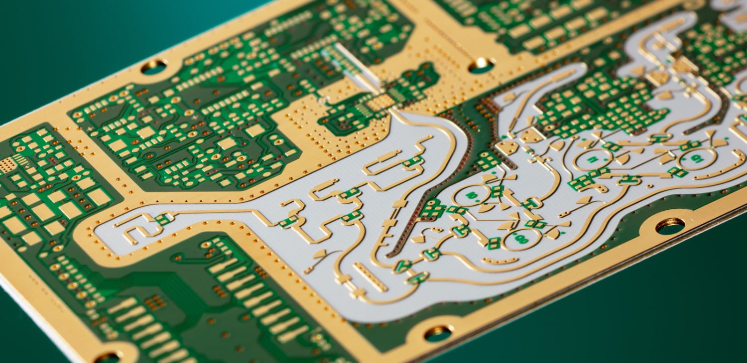
Rogers PCB?: A Rogers PCB is a type of PCB that uses reinforced hydrocarbon/ceramic substrates, this board keeps a low and almost constant Dk over high frequencies, and by high frequency, I'm talking about in the gigahertz range. These boards also have a very high Tg, with a Tg > 280 deg C (536 F), this means that the board wont break down until it reaches this temperature.
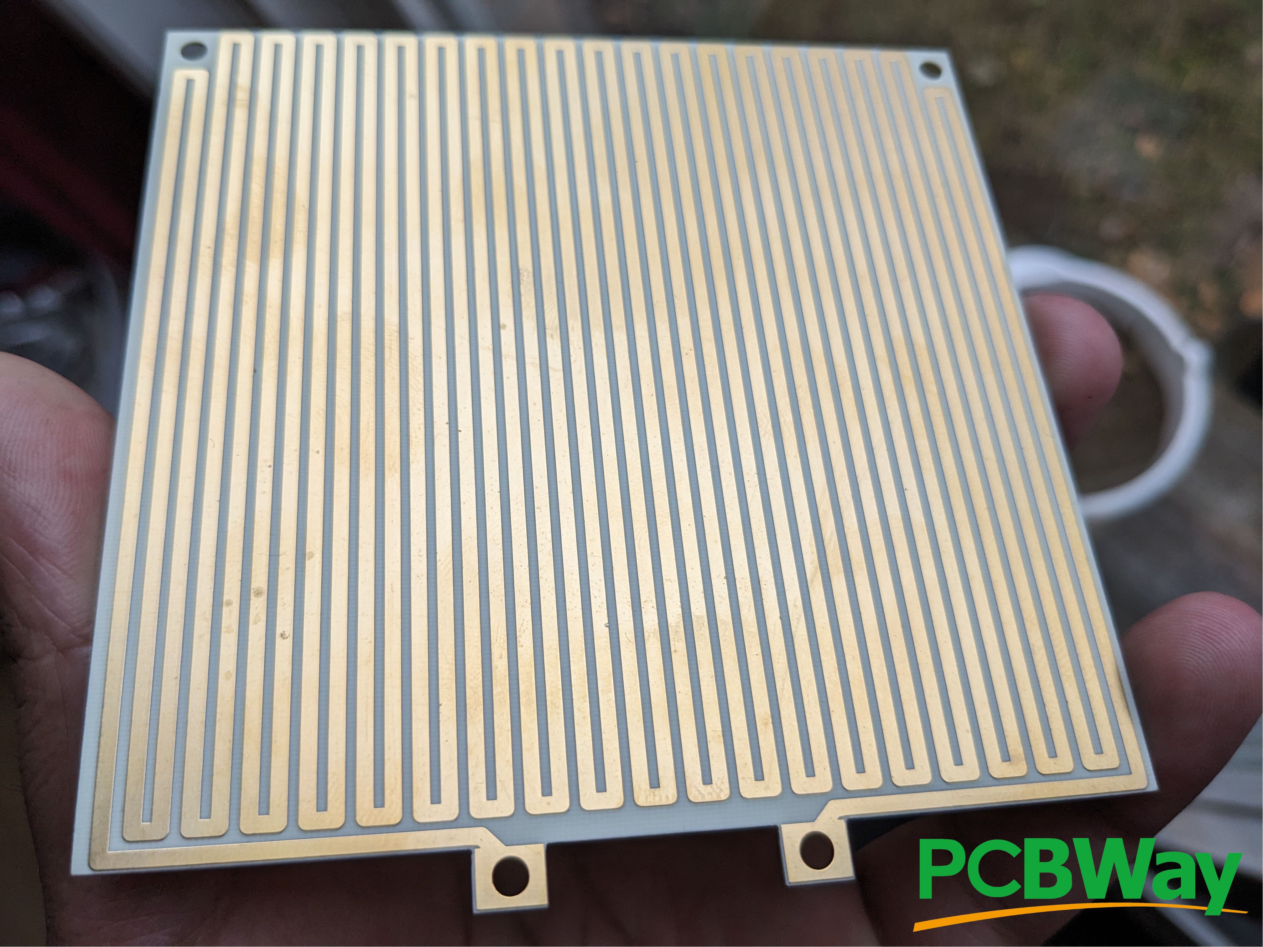
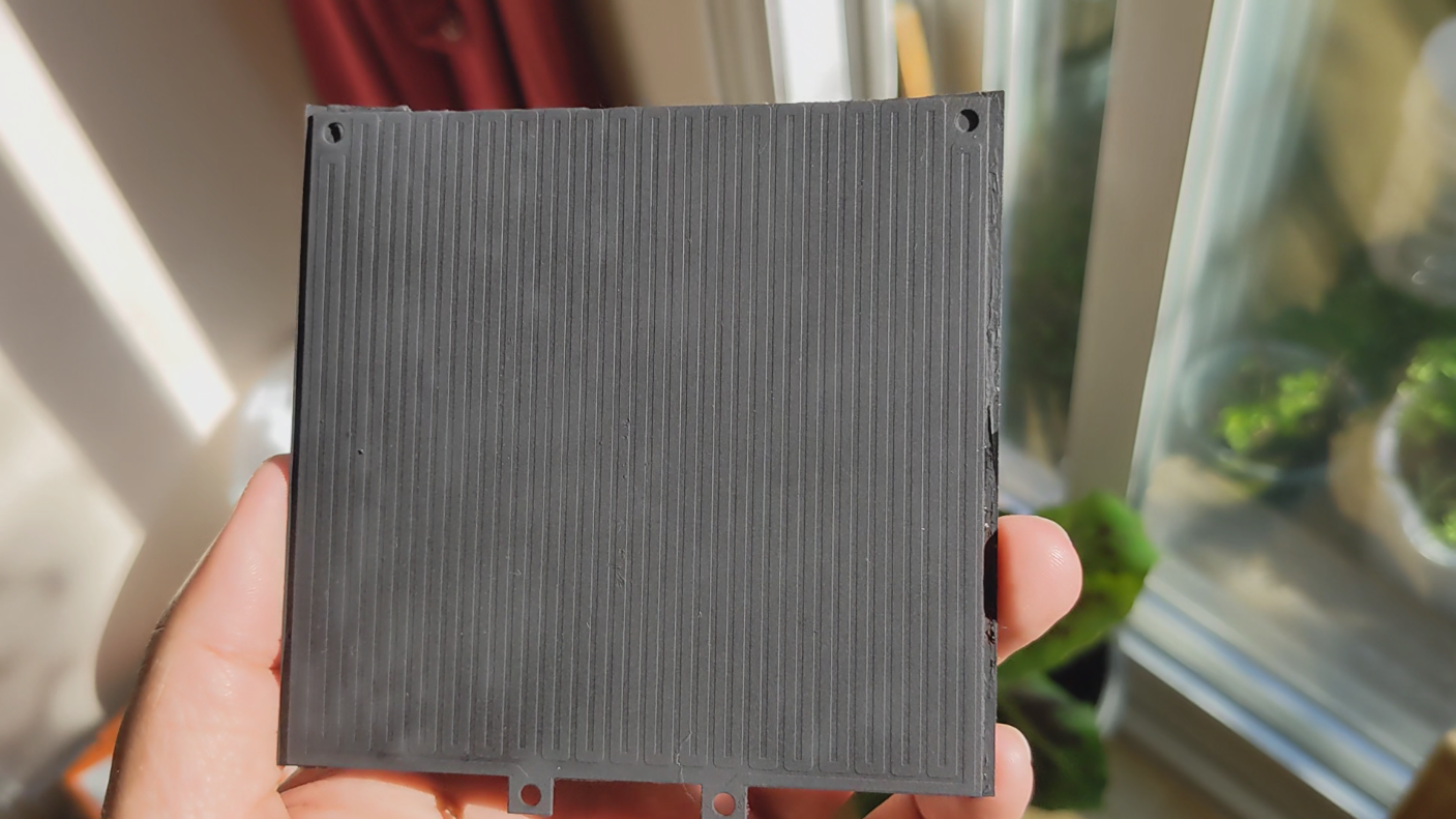
Heating Element: Since this PCB has a high Tg, I think it could be used as a heating element, although this rating is for heat exposed on the outside of the board, I'm thinking the value is high enough for it to be heated from the inside and remain fine. I made the PCB trace about 1.4 Ohms and removed the silkscreen since I was afraid it would burn. Since the silkscreen is gone the trace is exposed but covered by a thin layer of gold (ENIG) and wouldn't oxidize the copper, but I still needed to make the surface non-conductive, so I planned on using high heat enamel to cover the top. I got my boards at PCBWAY.
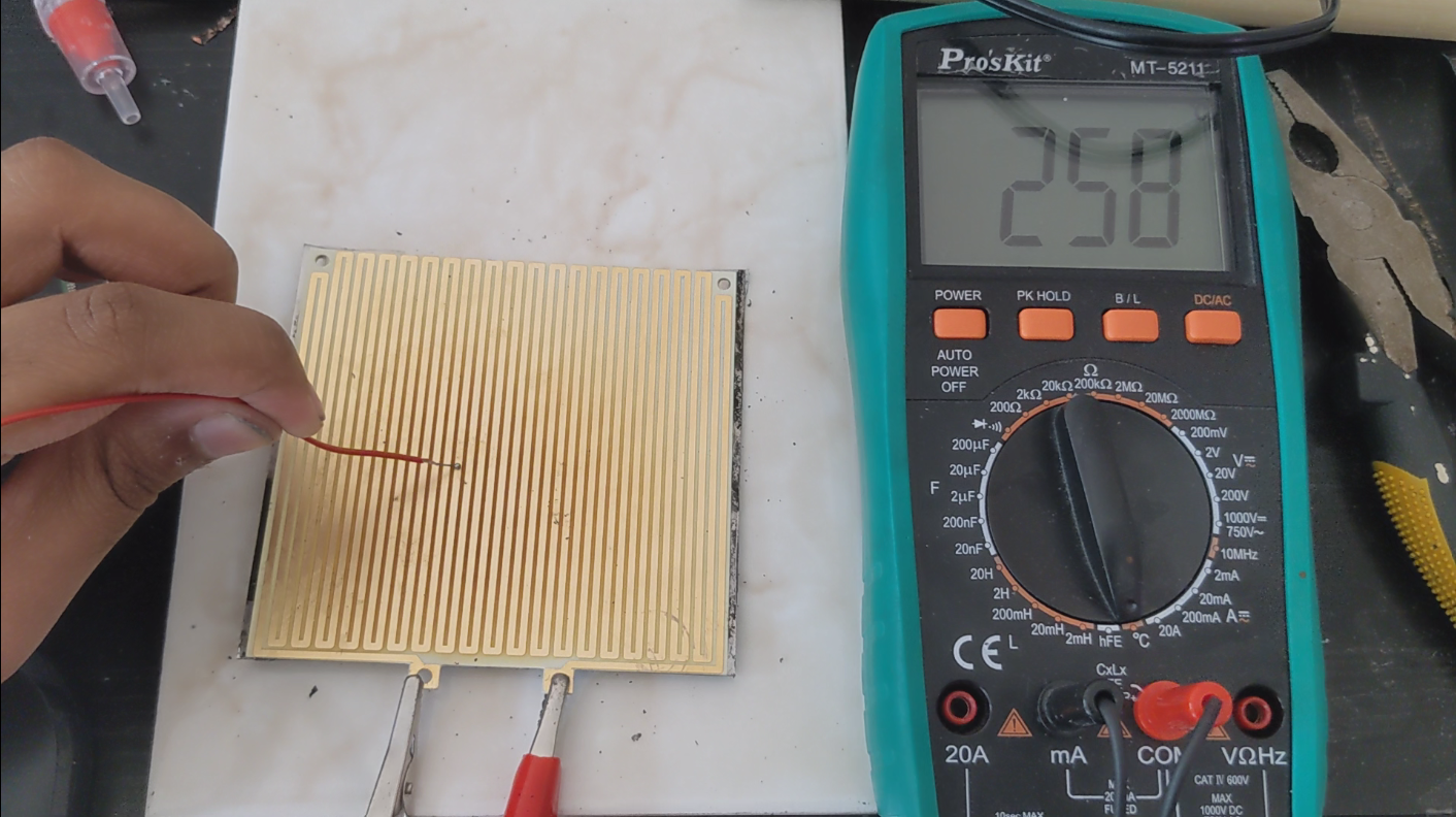
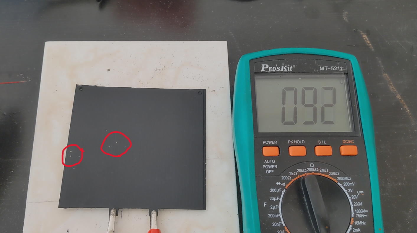
The Good: When I got the boards the resistance was exactly as calculated which has never happened to me before, and goes to show the accuracy of the boards. When I applied power, it reached my goal of 250 deg C (482 F) in under 2 minutes with around 12v and 8 amps or 96 watts.
The Bad: Above 200 deg C (392 F) the board started to burn, and became black, It also started to bend a bit due to thermal expansion. The board also started to smoke, but on the bright side the smoke smelled like a campfire, which was nice. The boards were also very expensive, it costed around 300 CAD (224 USD) for 10 boards, but it is costly to make these boards so the cost makes sense, luckily mine was sponsored so I didn't have to pay as much.
Trying to Fix it: First thing I did was add an aluminum plate at the bottom of the board, I know I should've added it to the top I didn't trust the high heat enamel thing to insulate properly. The main reason for the plate was to decrease thermal expansion and make the heat spread out more evenly. This fix almost eliminated the smoke problem. I put on the high heat enamel but as soon as I heated the board up, the paint would easily scrape off, I sanded the board and everything and followed the instructions exactly. Maybe I should have waited a full day instead of waiting until it was dry. When I tested it, I needed around 180w to reflow a pcb in around 2 minutes and 30 seconds, which is very high since I've seen people do it with around 60W, but this is probably due to how I have an aluminum plate attached to it.
Conclusion: This project totally destroyed my confidence in my knowledge of thermodynamics and material science. But this is still better than using a plain FR-4 board and will most likely last longer since those boards have a higher thermal expansion and lower Tg. I've definitely gave up on using PCBs' as heaters but I will not give up on making a low voltage, high temperature, and low cost heating element.
 PCB designer
 skelly
 Benchoff