 Mrinnovative
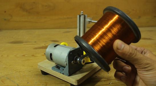
Hello friends in this video I have made a simple solenoid winding machine.
this machine is powered by two motors.
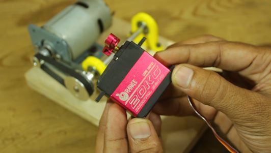
one is a 775 DC motor and one is a Servo motor,
First we will understand what solenoid is ?.
A solenoid coil is a coil of wire wound in a helical shape, often around a cylindrical core, that produces a magnetic field when an electric current is passed through it. The coil is typically made of insulated copper wire, and the core can be composed of various materials, including iron or steel.
When an electric current flows through the wire, it generates a magnetic field around the coil. The strength of the magnetic field is directly proportional to the current passing through the coil and the number of turns in the coil. Solenoid coils are commonly used in electromagnetic devices, such as solenoid valves, relays, actuators, and electromagnetic locks.
The basic principle behind a solenoid is Ampere's Law, which states that a current-carrying conductor produces a magnetic field around it. The solenoid coil enhances this effect by wrapping the conductor into a tightly wound coil, concentrating and strengthening the magnetic field.
In practical applications, solenoids are often employed to convert electrical energy into mechanical motion. When a ferromagnetic core is placed inside the coil, the magnetic field attracts the core, causing it to move within the coil. This movement can be utilized for various purposes, such as opening or closing a valve, switching an electrical circuit, or controlling the position of a mechanical component.
Supplies
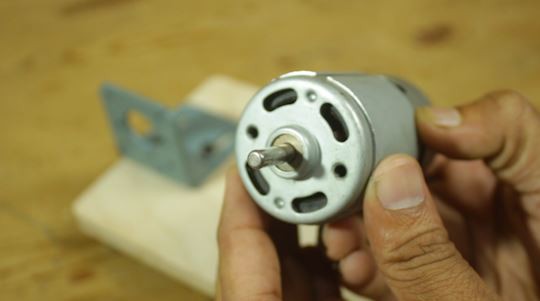
- 775 DC Motor
- 5V servo motor
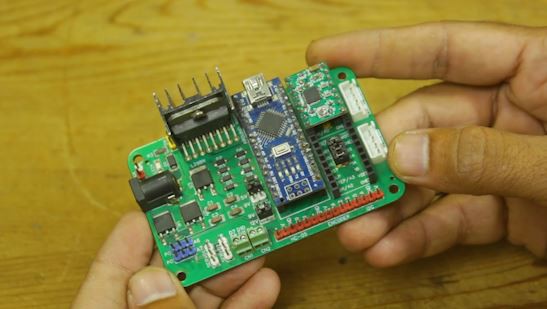
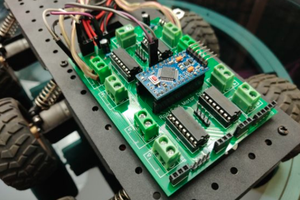
- Custom made PCB
- Arduino nano board
- wooden sheet
- 20x20 alu. extrusion
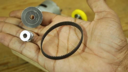
- Timing belt
- Timing Pulley
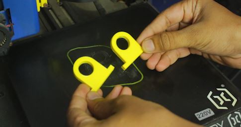
- 3D printed parts
- 5mm SS smooth rod.
- 5mm ID 17mm OD bearing
- 8mm smooth rod
- 8mm rod holder
Step 1: Making Wooden Base
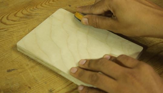
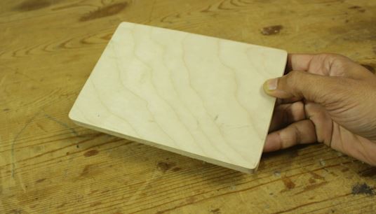
As usual for this machine, I have made a base of this machine from 12mm plywood.
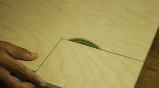
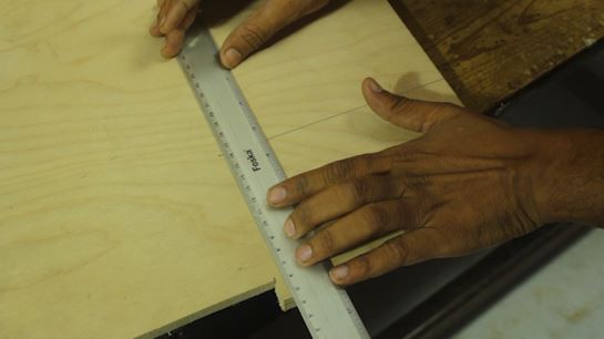
first I have cut the required size of wooden piece from the big wooden sheet.
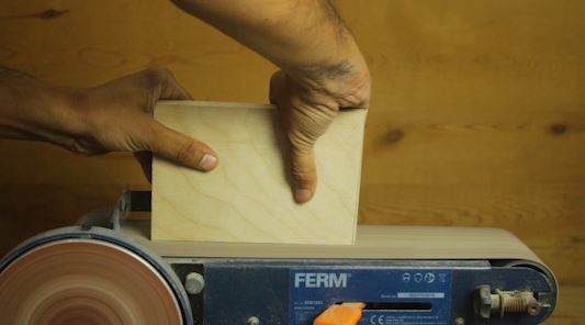
then I polish it with polish paper and smooth its edges by using my bench grinder machine
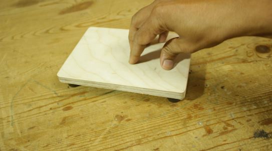
In this way very sturdy based is ready for our machine.
now we can mount the all components on this base
Step 2: MOTOR AND MECHANISM INSTALLATION
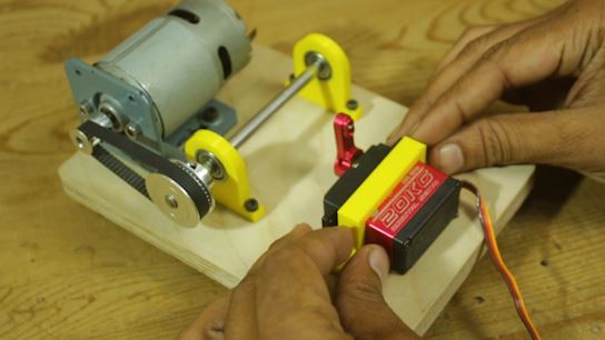
In this detailed guide, we'll walk through the step-by-step process of constructing an innovative wire winding system that combines a 775 DC motor, a solenoid rotating mechanism, and a servo motor.
This project involves a blend of mechanical engineering, 3D printing, and electronic control to create a versatile and efficient wire winding setup.
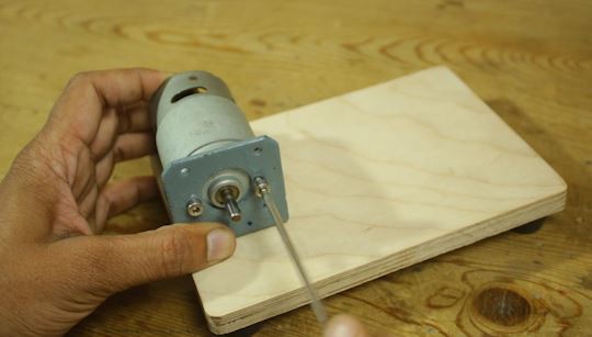
Step 1: Attaching the 775 DC Motor to the Clamp:
Begin by securing the 775 DC motor onto a stable clamp or base. The clamp provides a secure foundation for the motor, ensuring minimal vibrations during operation. Fasten the motor tightly to prevent any unwanted movement.
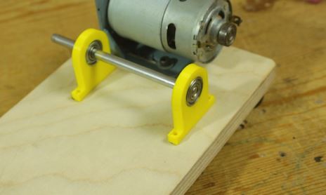
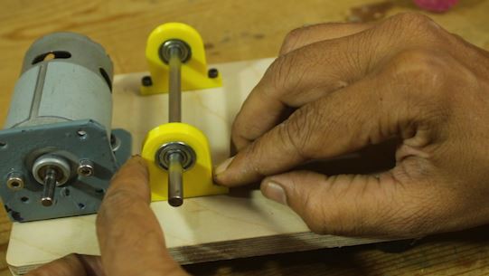
Step 2: Mounting the Solenoid Rotating Mechanism:
Utilize a 3D printer to create custom parts for the solenoid rotating mechanism. Attach these components to a 5mm smooth rod, using bearings to facilitate smooth rotation. Position the mechanism strategically, considering the movement required for optimal wire winding.
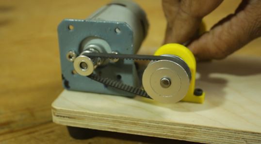
Step 3: Connecting the 775 DC Motor and Solenoid Mechanism:
Establish a connection between the 775 DC motor and the solenoid rotating mechanism using a timing pulley and timing belt system. This synchronization ensures precise and controlled movement, enabling efficient wire winding. Adjust the tension of the belt to achieve optimal performance.
Step 4: Installing the Servo Motor:
Integrate a servo motor into the system to guide the copper wire during the winding process. Position the servo motor strategically to ensure precise wire alignment. Program the servo motor to move synchronously with the other components for a seamless and controlled winding operation.
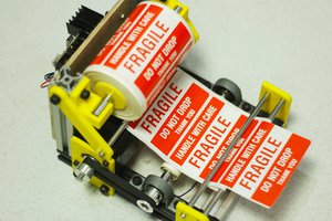
Step 5: Creating the Copper Spool Holder:
Design and assemble a copper spool holder...
Read more »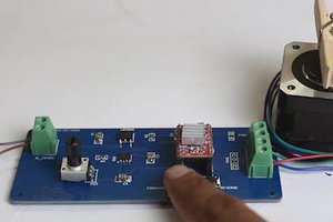
 Jithin Sanal