 PhoenixSeybold
At the QUT Robotics club (QUTRC) we are dedicated to fostering innovation and providing students with hands-on learning and practical experience in robotics.
The Australian Rover Challenge is a prestigious competition that brings together university students to design and build mock lunar rovers capable of navigating challenging terrains while performing tasks and showcasing our engineering abilities.
The challenge runs across 4 intensive days, with each bringing its own mission objectives and requirements:
- Landing Task
- Construction Task
- Institute Resources & Science Task
- Autonomous Navigation & Mapping task
Last year we attended the competition for our 1st time entry - Artemis, successfully achieving 4th place. We were also graciously awarded the title of "Best First-time Entry" by the competition organisers.
QUTRC A.R.C. Perseus
The Perseus project represents Queensland University of Technology Robotics Club’s (QUTRC) desire to field a second-generation rover (Perseus) in the Australian Rover Challenge in 2024 (Competition) and meet or exceed the requirements of each task in the Competition.
Perseus, a four-wheeled custom-manufactured rover, boasts modular sub-systems and an architecture prioritising robustness. A comprehensive electrical system overhaul, incorporating lessons from Artemis, is underway to fortify the Perseus platform for 2024.
Planned PCBs 2024:
1. Rover Control Board
intelligent power distribution, control & management
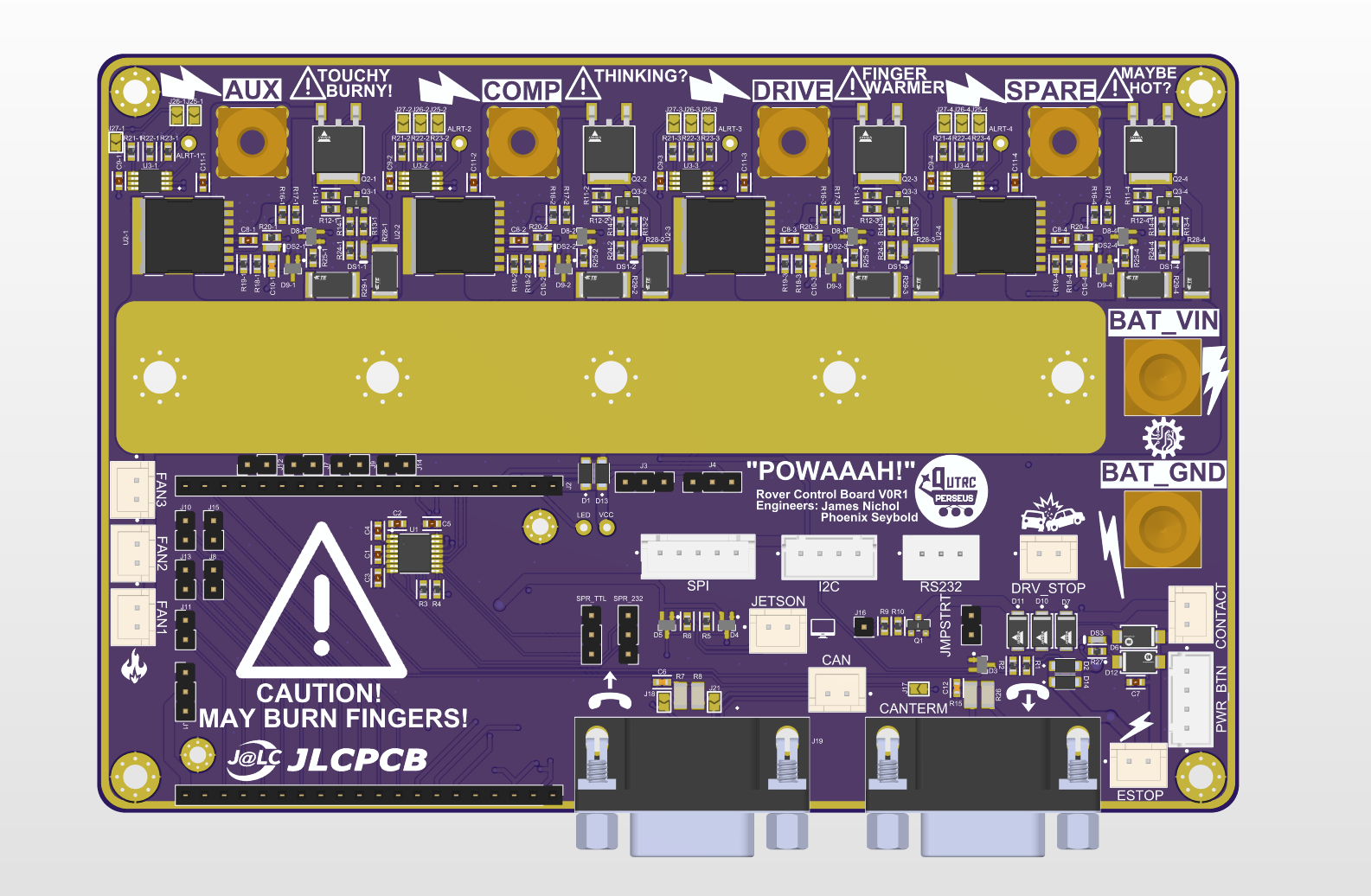
This is the heart of our electrical subsystem, serving as an intelligent high-current current bus-bar that delivers fine subsystem-level monitoring and control during operation. Due to large capacitive loads inherent with running 4 powerful BLDC motors the RCB also handles subsystem level pre-charge to reduce the strain of high inrush current in the system when switching.
Last year the RCB module drove 3x contactors to control power to each subsystem, in conjunction with pre-charge and current monitoring.
This year the RCB has been redesigned from the ground up as an all-in-one solution utilizing automotive-grade smart switches for high currents up to 100A per channel. Press-fit terminals are utilised to ensure ratings for high-current connections.
Power budgeting of the rover indicated a max worst-case current draw of 180A, therefore the board was designed for up to 180A continuous operation. To support this we adopted a 4-layer stack with dual 2oz copper power planes mirrored on the top and bottom of the board forming an integrated bus bar. Additional bolting mounts allow for the expansion of the busbar by bolting down a copper plate to accommodate larger currents & better heat dissipation.
A main contactor is still in use to provide the E-stop with an emergency physical disconnect of all power.
This board is built to be driven by our embedded system module, called the Smol Brain Board (SBB), and serves as the highest point of control for the rover. All communication is passed and read over the rover’s CAN bus network.
On start-up, the RCB runs an intelligent boot sequence that monitors voltage and current to ensure safe operation.
Logging and Error states are published over the CAN and to the integrated I2C display for efficient diagnosis of issues and to ensure fast action can be taken on the day of competition.
2. Smol Brain Board - SBB
Embedded System Module
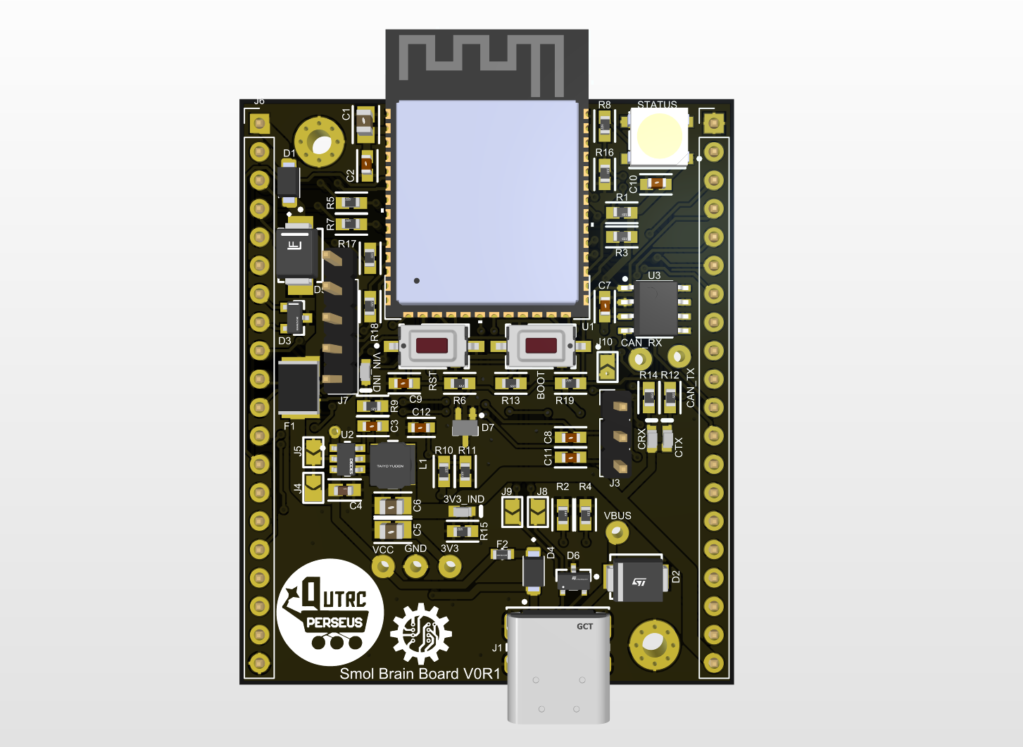
This is our custom-embedded compute module designed to be dropped into any PCB that needs to interface with the rover system. It contains all required commonalities between PCBs such as:
- ESP32-S3 WROOM N8 module
- AP63203WU Buck Regulator: 32V → 3.3V 2A
- CAN bus
- Over current protection
- Dual Protected Power supply - can be supplied from battery, or over USB
It breaks out 39x GPIO including 10 ADC channels, 2x UART, 1x SPI bus, and 1x I2C bus.
3. Motor Control Boards - MCB
CAN bus-controlled motor driver module
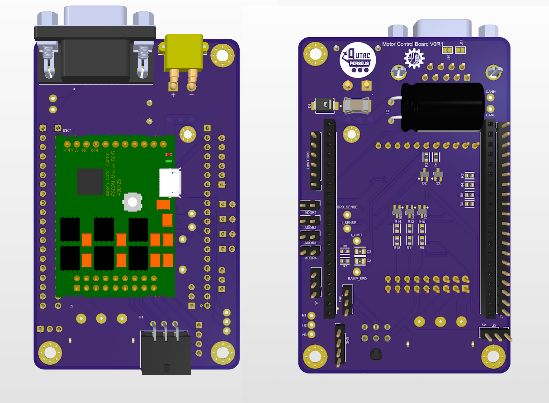
These boards interface our SBB modules with the rovers...
Read more »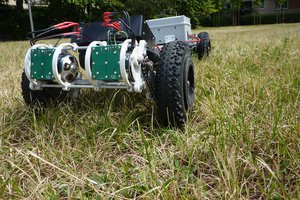
 Luke
Luke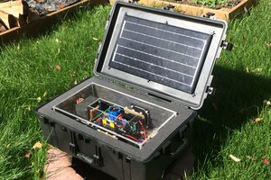
 oneohm
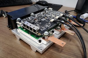
 Marcos
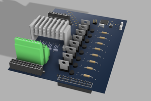
 UFRJ-Nautilus