 Foxtek
Hey Hackaday community! Exciting news for all DIY enthusiasts and tech wizards out there - meet the FlexiTimer FX486, a programmable timer that's breaking new ground. Born from a provisional patent application, this device is redefining what a standard timer can do.
Designed to endure, the FlexiTimer comes in a rugged, waterproof casing, making it perfect for harsh environments. Whether you're in a lab, a workshop, or outdoors at a sports event, this gadget is built to last.
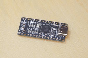
At its heart lies an Arduino Nano Every microcontroller, chosen for its reliability and ease of programming. This means you can tailor the FlexiTimer for just about anything, from industrial to educational applications.
The 8-digit segment display, driven by a MAX7219 integrated circuit, ensures you'll always have a clear view of your timings. And for updates? The built-in USB-C connectivity makes it a breeze.
But the real showstopper is the FlexiTimer's incredible modularity. Its 12-pin input/output connector lets you hook up a plethora of external modules. Temperature sensors, I2C modules, or even serial communications – the sky's the limit!
Added to the mix are a programmable buzzer and LEDs for audio and visual alerts. Plus, there's a L7805CV TO220 voltage regulator ensuring a steady 5V power supply and capacitors for smooth power delivery.
Whether you're a seasoned engineer, an enthusiastic educator, or a weekend tinkerer, the FlexiTimer FX486 is here to elevate your projects to the next level.

 5Volt-Junkie
 Denis
Denis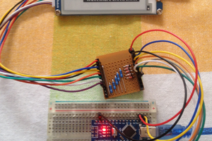
 agp.cooper