Close
0%
0%

Sailing the 7 Seas -- nautical blinkenlights

Nautically correct blinkenlights that flash just like the real lighthouses and buoys; on a colourful nautical map thanks to JLCPCBs new PCBs

Public Chat
Similar projects worth following
198 views
0 followers
There are two things you can never get enough off - nice looking maps with lovely typography and blinkenlights. So when EasyEDA grew a, somewhat, hidden feature coled "Colourful Silkscreen Printing" - they had to be combined.

Basically what this is is full colour, high resolution, CMYK printing of one side of your board; while still having all the PCB options, via's, ENIG and other features preserved for both sides of the board.

Note that this is not yet something that appears in production - but they give early access to us makers to this via their OSHW Lab Stars programme: https://oshwlab.com/activities/spark2023.

This was a very painless process; just hit that link, submitted your design via EasyEDA & it arrived some 5 days later in the Netherlands.

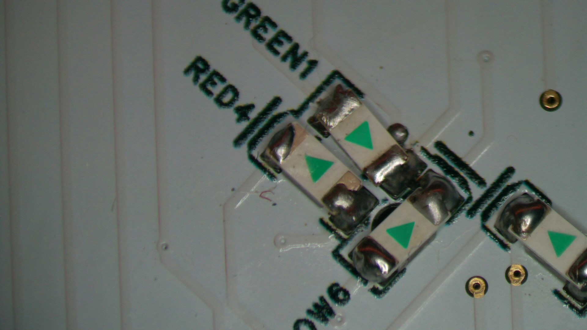
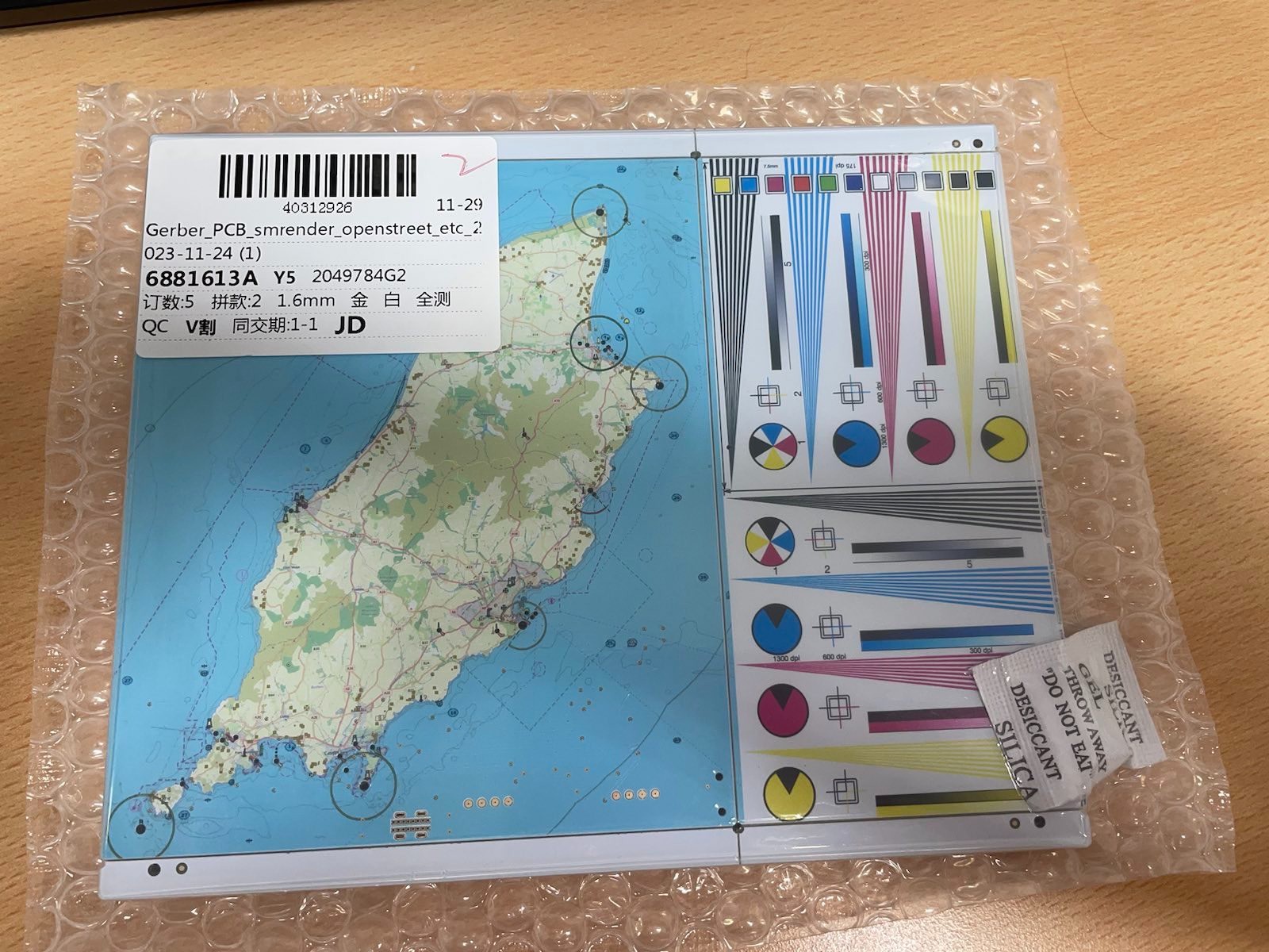
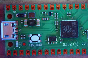
So the rough plan is to get a good looking nautical map printed on the front of the PCB using this new Colourful Silkcreen PCB option at JLCPCB that was added to EasyEDA PRO. Then, inspired by the article ``THE SCIENCE OF REVERSE MOUNTED LEDS'', mount LEDs on the back of the map exactly in the spot of a lighthouse, buoy and so on. And them have some Arduino or similar flash these in the right patterns. And finally submit this to EasyEDA their Spark 2023 trial programme.

Lights

As to some background - maritime navigations at night relies in no small part on beacons, lighthouses and buoys with lights that flash in particular colours and lights. With a fair bit of coordination to make sure that any pattern than you can reasonably see (i.e. given the curvature of the earth and so on) is unique.

This is patterns, known more formally as Light characteristics, are shown on naval charts, in pilot guides and Almanacs. These use an abbreviated form; such as 'F R' or 'Oc R(4) 30'. Which then translates to it being a fixed red light; or a light that is occulted shortly 4 times in a 30 second period.

Now a lot of these codes may appear terribly underspecified (to a programmer or mathematician) and incomplete. This is largely as there is a historic assumption that most `flashing' lights do not actually flash (historically that would either be impossible with a flame; or burn our the filament at those high intensities). Instead - the flashing was achieved by shades moving in front of the light; typically by a set of these rotating around the light on a clockwork. And that meant that it was easier to occult (i.e. shortly dip rather than flash), and that patterns where easiest when they are regularly spaced within the repeat period. So there is a bit of mental model to apply when translating these codes into actual flashing patterns. But more about this later.

Maps

The next issue is that of maps. We could, of course, scan an existing naval map; and simply crop and scale this down to size. But that would be far too easy. Thanks to project such as OpenCPN, maps like OpenSeaMap, OpenNauticalChart and Open Street Maps have come leaps and bounds in recent years in terms of supporting sailors. 

And thanks to their open APIs - it is not hard to extract the right vector data. In theory. And with lovely tools, such as Bernard R. Fischer his SMRender it is easy to just select some area and render a PNG, SVG or PDF with just the right data; in a nautical style. And to make things even easier; it the documentation even details how to extract the light characteristics.

Rasterizing

Now naval maps have historically been quite reliant on many layers of spot-colour printing; as opposed to a single CMYK run in which the dots are so small that they optically merge into a single colour. Now this poses a bit of a challenge because that historic spot-colour technique excels at very crisp, think (black) lines and large areas of one colour with abrupt changes possible. And over time - the chart makers have learned how to make really good use of this - improving the way information is presented in tandem with the printing technology.  


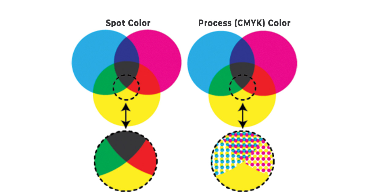
Spot vs CMYK printing

CMYK however is quite `bad' at crips lines and areas of one subtle shade. This is as it relies on an optical trick of mixing 3 colours (Cyan(C), Magenta(M) and Yellow (Y)) to create the illusion of some other colour, like green, red or brown. With Black (or "Key", the final K of CMYK) thrown in as to get a rich black. And then using some sort of average diffusion (or dithering) to roughly get the right mix.

This works really well for things that have a natural flow and many shades; such as a photograph of a person or nature. But not exactly for the case where you have one area, say, in light blue, thin black line and then a darker blue area. The colours will blend a bit; and the black may smudge because it is touched by dots on either side.

The issue...

Read more »

Portable Network Graphics (PNG) - 1.23 MB - 12/30/2023 at 12:46

Preview
Download

Adobe Portable Document Format - 784.09 kB - 12/30/2023 at 12:46

Preview
Download

Adobe Portable Document Format - 1.18 MB - 12/30/2023 at 12:46

Preview
Download

Portable Network Graphics (PNG) - 143.64 kB - 12/30/2023 at 12:46

Preview
Download

  • Generating a playlist for the LEDs

    Dirk-WIllem van Gulik12/29/2023 at 21:55 0 comments

    With this we can generate a playlist for the LEDs. And with a very simple player we can play these out as text for debugging. Or shunt into the PCB as firmware.

  • Getting Light Characteristics

    Dirk-WIllem van Gulik12/29/2023 at 21:51 0 comments

    So we have a working set of blinkenlights. The next challenge is translating the map sequences to the right flashing lights. And get this stuff compact enough to fit in the few 100 bytes we have in a STM8 CPU.

    There are some libraries in Pascal, Javascript and Python that allegedly convert these sequences. The first attempt with python its light-character seems to output sensible code.

    Running various sets of lights show that most of the generated sequences have a lowest common `shortest change time' somewhere in the 0.2 to 1 second; and that the most complex sequences are early longer than 20 steps or 50 seconds. 

    This means that writing these out as sequences of bits is not ideal; but that some sort of playlist would likely fit in a few bytes per steps if we accept that we need to store 2 or so values per light. With the above - these appears to still fit in 8bits. So that is doable for the 30-50 lights typically expected.

  • Testing the LEDs

    Dirk-WIllem van Gulik12/29/2023 at 21:38 0 comments

    Next up is testing the LEDs and the Driver; see this code. Things work first time :)

  • Day 16 - Bringup

    Dirk-WIllem van Gulik12/29/2023 at 21:31 0 comments

    Next up is bringing up the board.

    This was done in several steps; first one board was readied with just the CPU, power conditioning, the power LED and the 'ACT" debugging LED. But without the LED driver or any of the LEDs.

    For this a simple programme was written:

    // Test LED "2" -- R124 needs to be in place or jumpered
    //
    #define LED_PORT    PC
    #define LED_PIN     PIN4
    
    int main(void)
    {
        /* Set clock to full speed (16 Mhz) */
        CLK_CKDIVR = 0;
    
        /* GPIO setup */
        // Set pin data direction as output
        PORT(LED_PORT, DDR)  |= LED_PIN; // i.e. PB_DDR |= (1 << 5);
        // Set pin as "Push-pull"
        PORT(LED_PORT, CR1)  |= LED_PIN; // i.e. PB_CR1 |= (1 << 5);
    
    	while(1) {
            // LED on
            PORT(LED_PORT, ODR) |= LED_PIN; // PB_ODR |= (1 << 5);
            delay(100000L);
            // LED off
            PORT(LED_PORT, ODR) &= ~LED_PIN; // PB_ODR &= ~(1 << 5);
            delay(300000L);
        }
    }
    
    The full code can be found on GitHub.

  • Day 14 - soldering

    Dirk-WIllem van Gulik12/29/2023 at 21:22 0 comments

    Next up was a bit of experimentation as how to solder this; without ruining colour.  Using a relatively hot SMD oven caused a slight browning of the imagery. The same was found when using a hot air gun indiscriminately.

    Normal traditional soldering; or gentle hot-air in limited areas worked well - with no discolouring discernible. The one exception was near the USB-C connector. One needs to really heat this up to get the solder to flow well enough for a good mechanical fix (future versions probably should simply use two power pins; rather than USB to prevent this).

    The reverse LED soldering was slightly more challenging. As we wanted them to be `on top' of the PCB - rather than `fall' through a square hole. 

    Turned out this was best done by putting a small blob of solder on one side; hold the LED against it; solder that one side; then let solder flow under the older side. And then complete the first side.

  • Day 12

    Dirk-WIllem van Gulik12/29/2023 at 21:14 0 comments

    About 12 days later (most of this was taken up by shipping) - the post brought a nice looking box:

    With 5 very lovely looking boards !

    All nicely packaged and sealed.

  • Day 2 - design sent off

    Dirk-WIllem van Gulik12/29/2023 at 21:13 0 comments

    The final design was submitted to JLCPCB.

View all 7 project logs

Enjoy this project?

Share

Discussions

Similar Projects

Does this project spark your interest?

Become a member to follow this project and never miss any updates