 Juan Flores
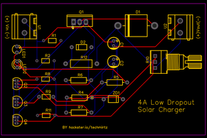
This project is a module that allows charging a Li-Po battery from two different energy sources and provides a constant output voltage independent of the battery voltage, with minimal losses to ensure long-lasting operation in low-power applications. It works correctly with a solar panel, hence its name.
The project itself can be divided into two blocks:
The first would be the charging circuit, which uses a CN3063. I primarily chose this component because it is widely used in single-cell Li-Po charging modules. The datasheet provides a circuit sequence for using two different energy sources. Essentially, this circuit is an N-type MOSFET transistor with the drain connected to the positive of the solar panel and the gate to the USB positive.
This means that if the USB is connected, the gate voltage will be equal to or lower than the drain voltage, preventing current from flowing through the transistor. However, if the gate voltage is 0, the current will flow from the solar panel to the component, bypassing the USB with the Schottky diode. This diode was chosen because the circuit is limited to 500 mAH, and we want the least possible loss, so it suits well. This limitation is due to the resistance we have used in the component, which is 3.6K to cut the charge to a maximum of 500mA.
Likewise, I have added a screw connector to connect the solar panel, a 2mm PH connector to connect the battery, a USB Type C connector without end-of-line termination to also limit it to a maximum of 500mAh and without a data line. Finally, I added pins to connect a multimeter to more easily check the battery level or to solder it there.
Regarding solar charging, there are a few things to consider. It would work with solar panels from 4.5V to 6V, but ideally, a maximum of 5V should be used. Also, the charging speed depends on the panel's power. The one I use is 0.2W at 5V, meaning it generates 40mAh at full performance, so it would take 10 hours in full sun to charge a battery like the one in the video (500 mAH). What I mean is that when choosing the panel, these data should be considered.
The second part of the circuit is about the TPS63020. This component is a buck-boost, step-down, which will increase the input voltage when it is below the desired level and decrease it when it exceeds, providing a constant voltage.
This component is very interesting as it allows configuring the output voltage based on the voltage divider connected to the feedback pin (pin 3). The datasheet already gives some values for a 3.3V output, which is what I was initially looking for, but we could basically leave the 180k resistor and change the 1M resistor to obtain different voltages, such as replacing the 1M resistor (R4) with a 1.6M one for a 5V output. (See photo 3)
This resistor, I have slightly set aside, as can be seen in the photos, to make it a bit easier to desolder. Finally, the component has a system for selecting low power or normal mode. The low-power mode consumes around 50uA, which is negligible, but it causes the voltage to drop at the output if the load consumes little (I don't know how little that would be). On the other hand, in normal mode, I haven't been able to measure it, but I've left a battery without charge connected for weeks, and the charge has hardly decreased, so I believe it must be considerably small.
 Christoph Tack
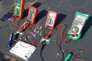
 Jasper Sikken
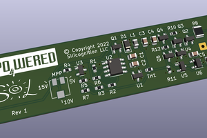
 Patrick Van Oosterwijck