Project Logs:
0%
0%
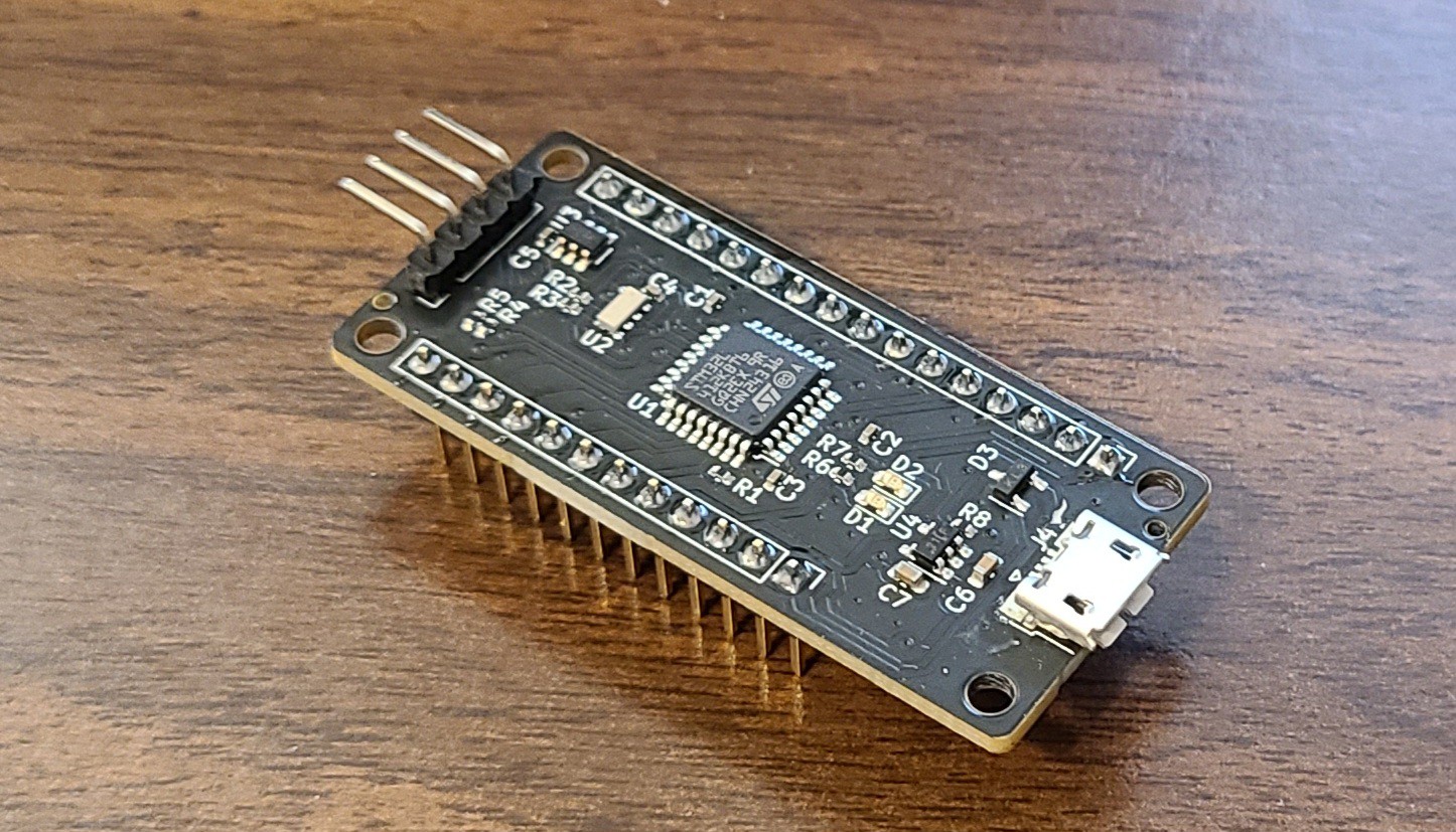
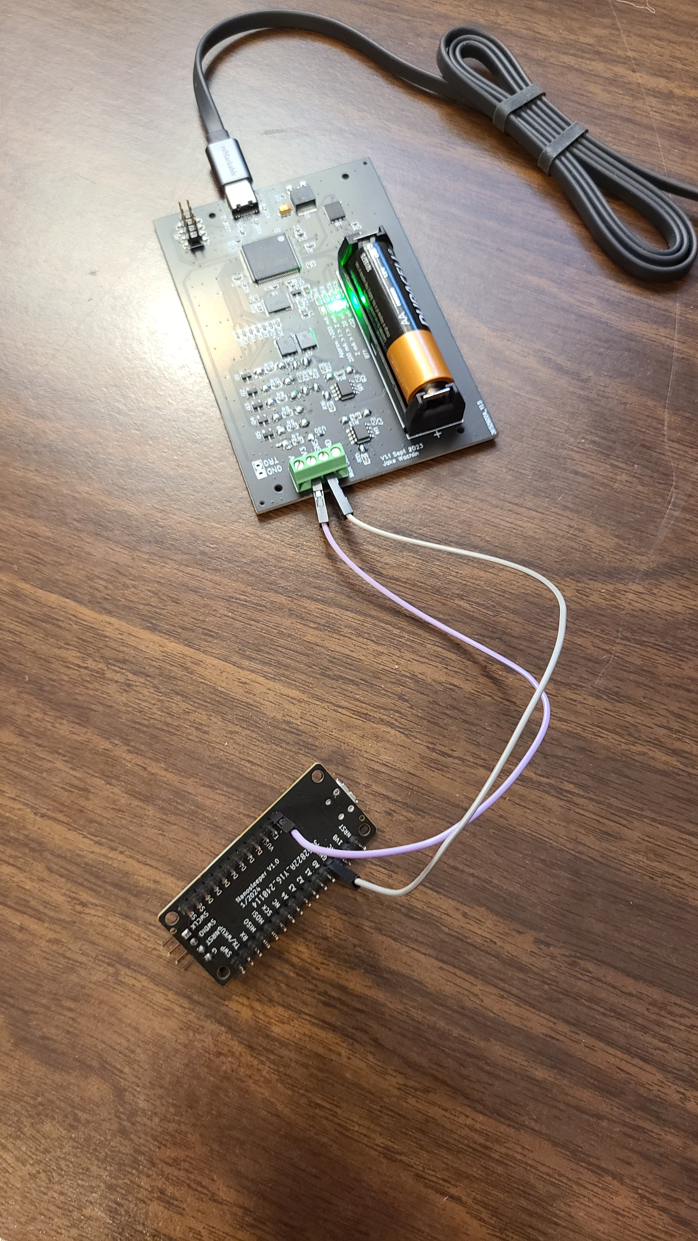
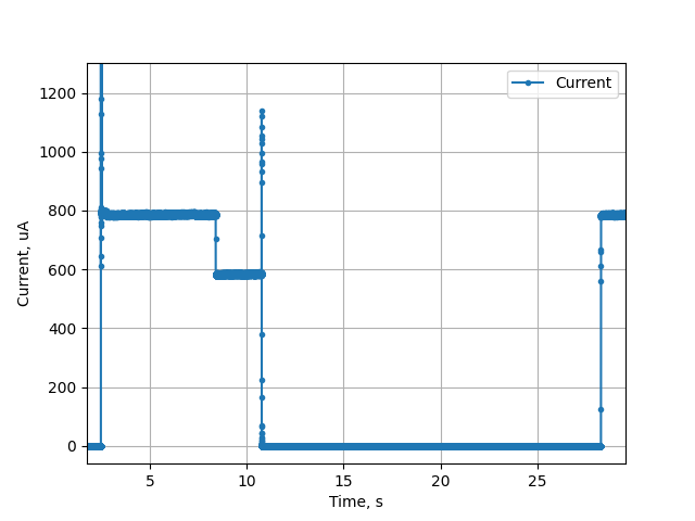
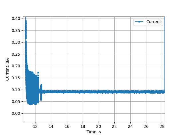
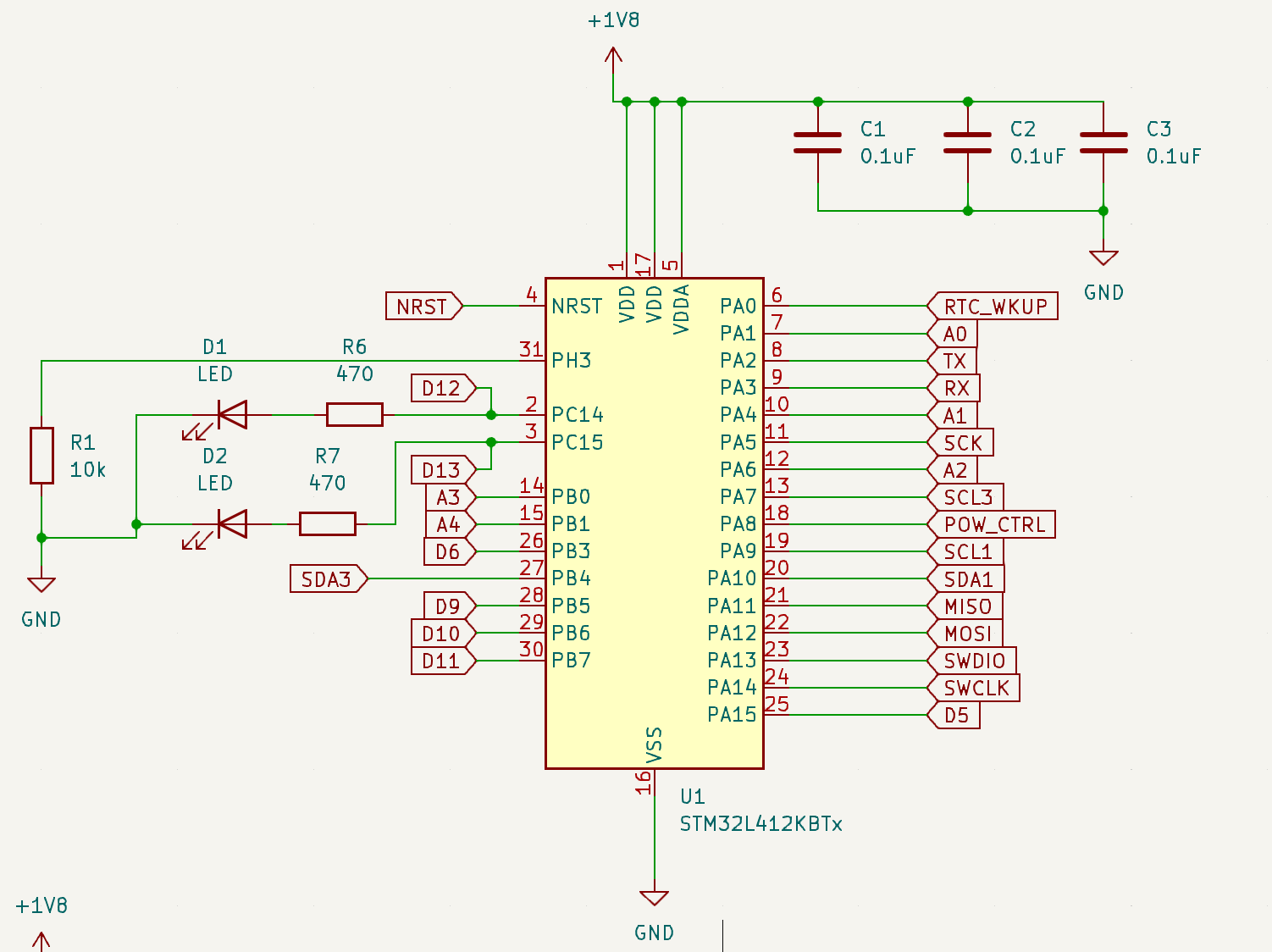
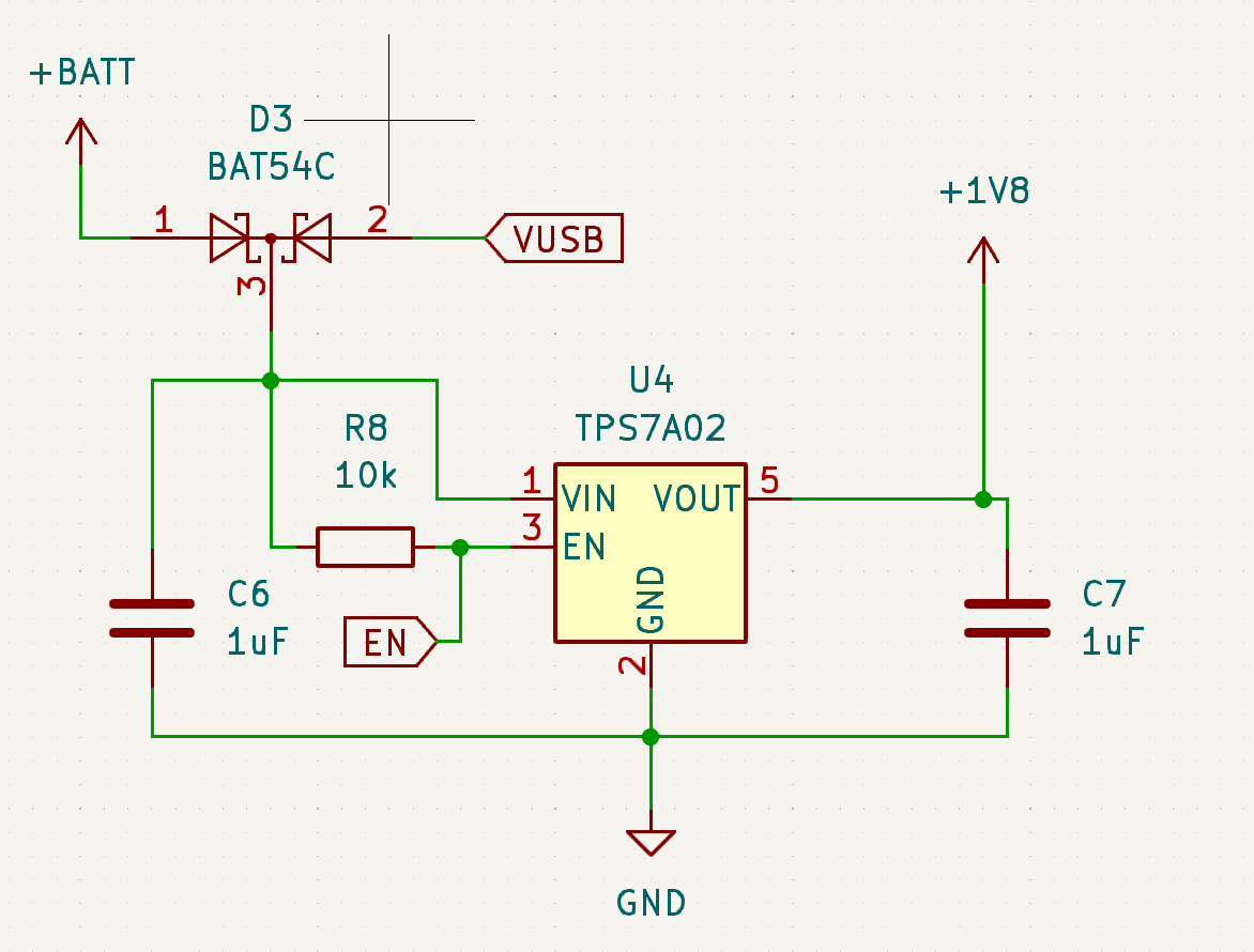
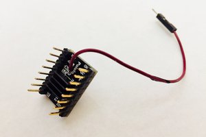
Nanosleeper - Sub 100nA Sleep Dev Board
A "feather-ish" development board achieving <100nA deep sleep current with real time clock wake-up
Become a Hackaday.io member
Already have an account? Log in.
Just one more thing
To make the experience fit your profile, pick a username and tell us what interests you.
Pick an awesome username
hackaday.io/
Your profile's URL: hackaday.io/username. Max 25 alphanumeric characters.
Pick a few interests
Projects that share your interests
People that share your interests


 Stefan Wagner
 Sukasa
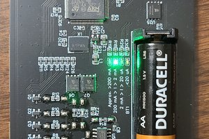
 Colin MacKenzie
Hi @Stephan Walter thanks for pointing out those alternative RTCs! Maybe I'll make an even lower current option in the future for those who don't need precision timing!