 potblitd
Idea
The project is meant to create yet another 'digital clock made of analog clocks', but different. So these are the main requirements for this design:
- Use cheap and easily available components
- Simple setup with as little parts as possible
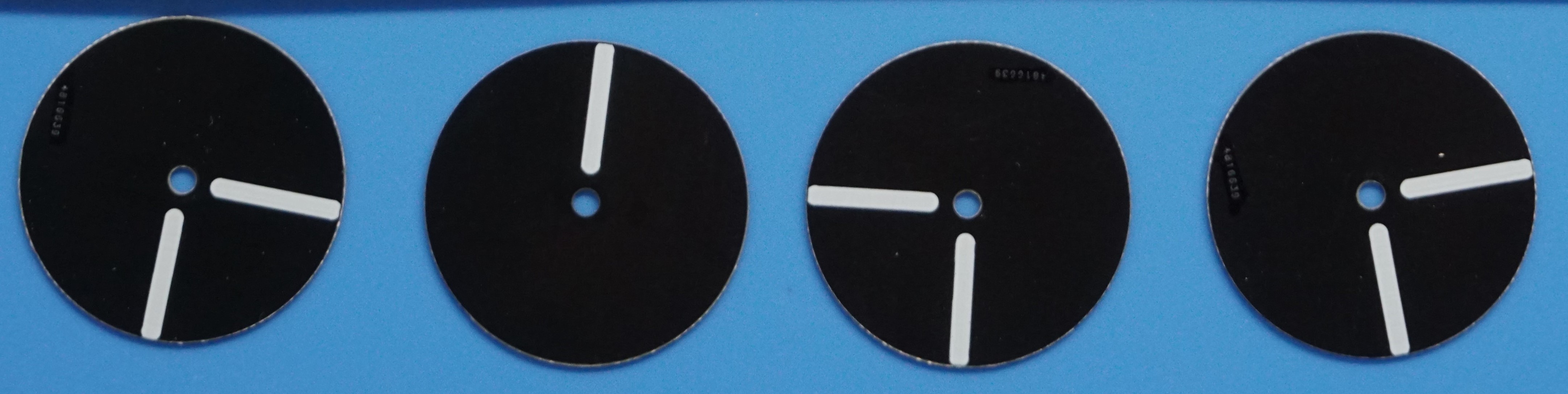
- Use overlapping disks, with a 180 degree range
- Small and simple to program MCU
- Fully assembled PCB (no modules)
- USB type-C power and programming
Design
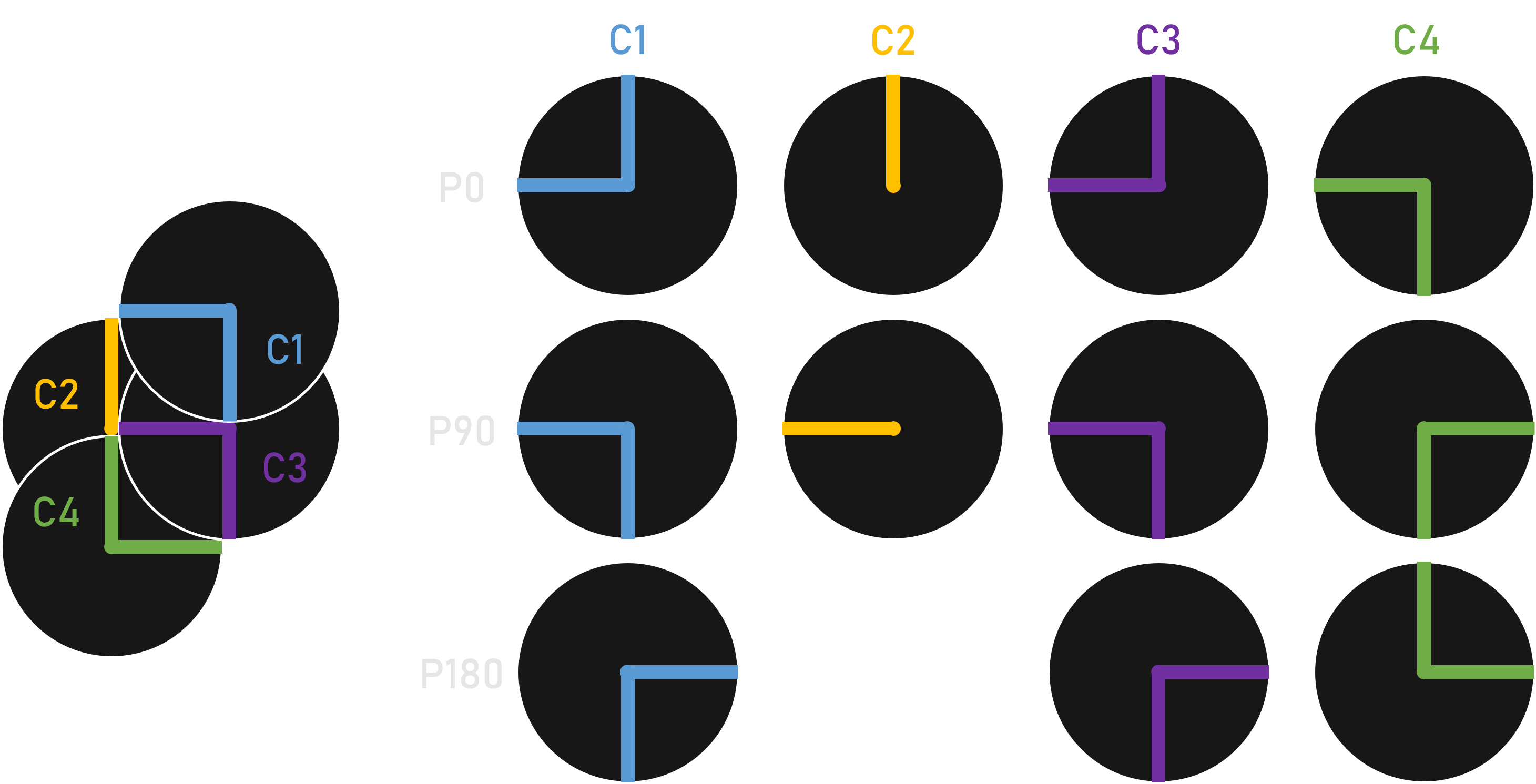
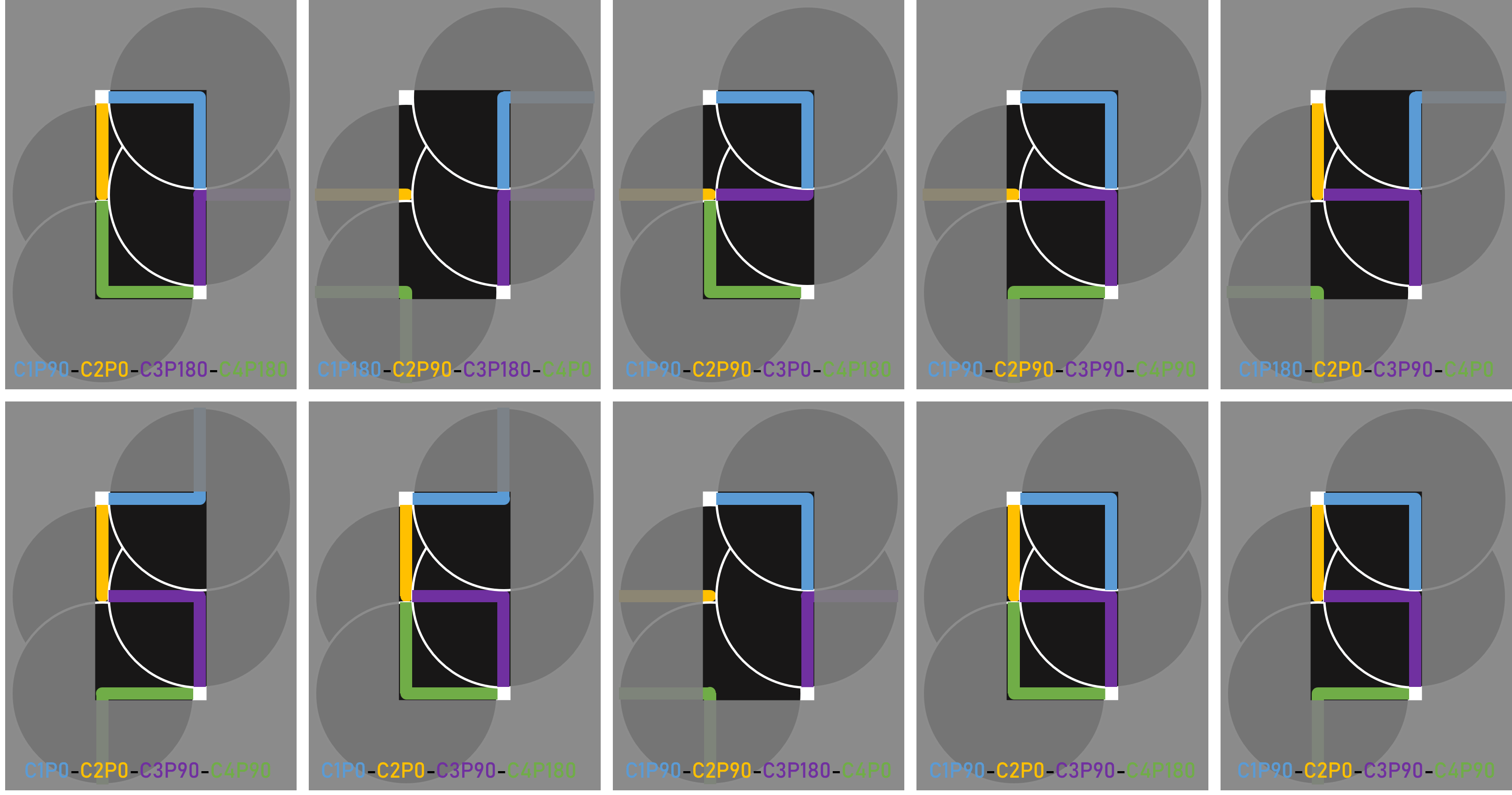
The overlapping disks must be arranged in a way so that their segments can forma all 10 digits (0 to 9). First, the minimum number of axis needed to accomplish this is 4. So then these 4 disks must be placed at one of the segments intersections while considering their layer order. Each digit can be described by the 4 disks positions, which is helpful for the programming later on.
Components
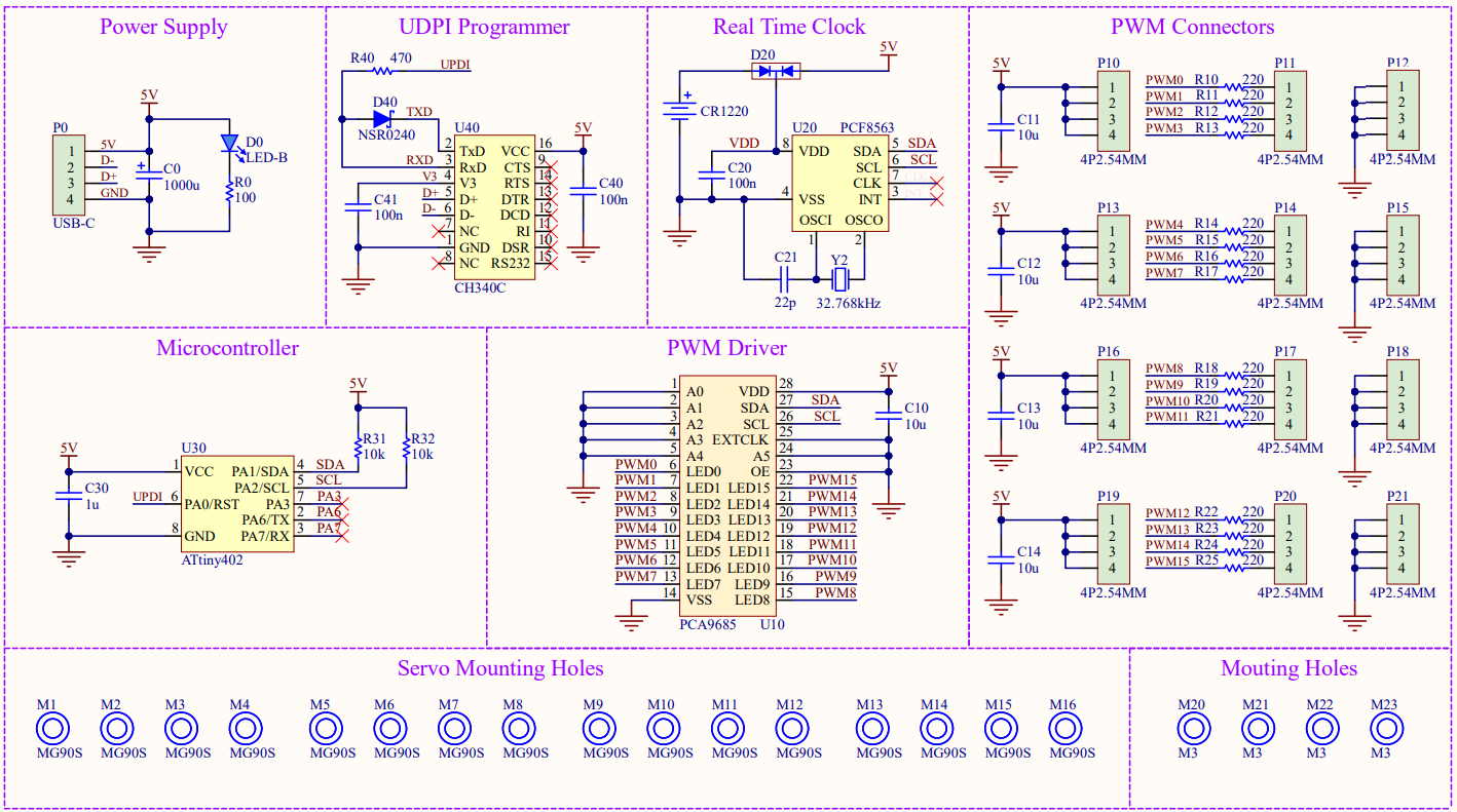
The servo motors are driver by the popular PCA9685 PWM controller and the time is fetched from the PCF8563 real-time clock. As the microcontroller of the system only needs to write and read with the two other chips through I2C, the ATtiny402 is very suitable (and my personal favorite). The MG90S servo motors are less noisy and their motion is more smooth and precise than the cheaper SG90, which are necessary features for this application. For programming the ATtiny over USB, the CH340C is added as it has a simple footprint (SOP-16) and does not require an external oscillator.
- ATtiny402 microcontroller
- CH340C USB to serial
- PCF8563 real-time clock
- PCA9685 PWM driver
- 16 x MG90S servo motor
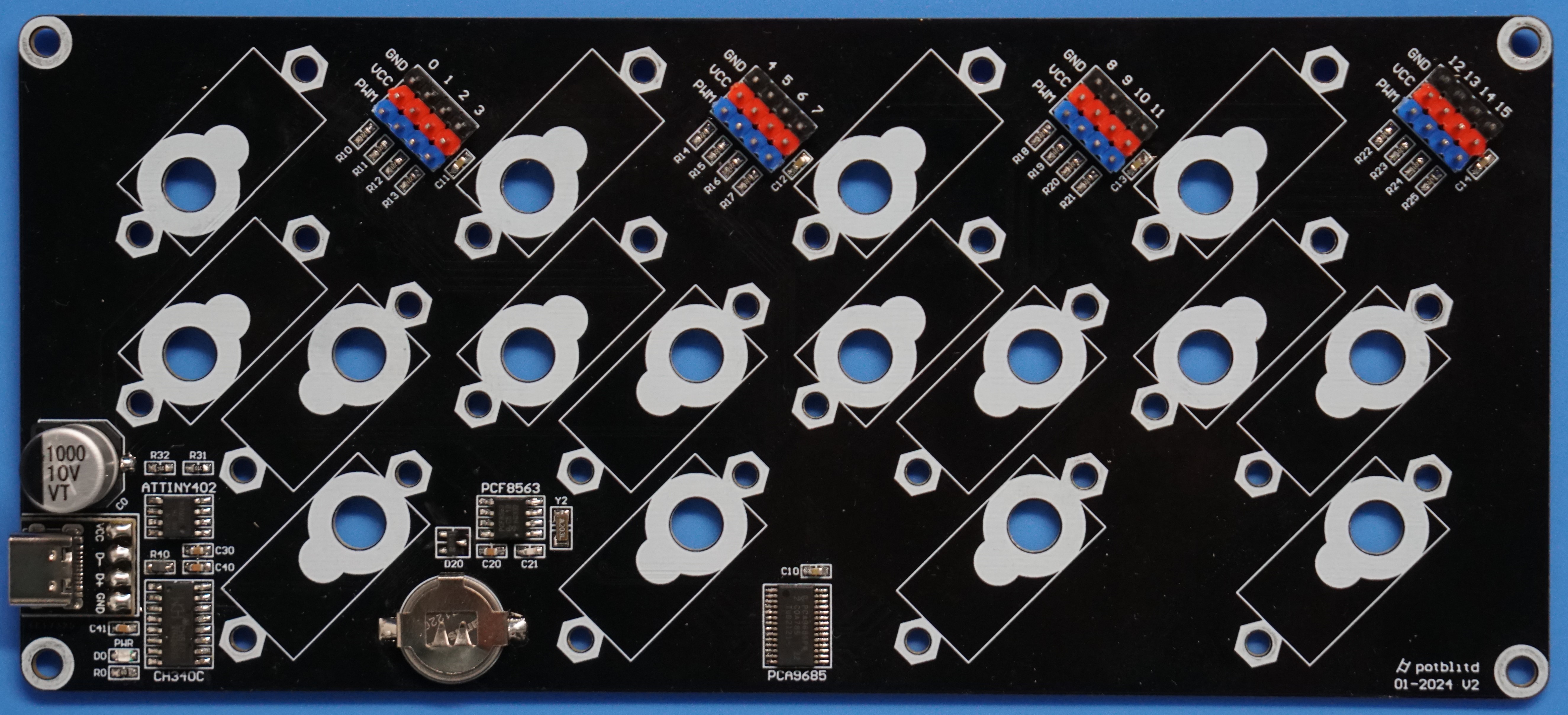
Schematics
The system is powered through a USB-C port (on a breakout board) and its status is indicated by a blue LED. For the 16 servo motors, the power supply must be able to provide at least 18W. Programming the ATtiny402 is accomplished through the CH340C chip with the Schottky diode between RX and TX to allow UPDI. The RTC chip has a CR1220 coin cell as an auxiliary power source to keep the time running while unplugged from the USB-C connector. As only one PCA9685 driver is required, its I2C address is hardwired to the default value.
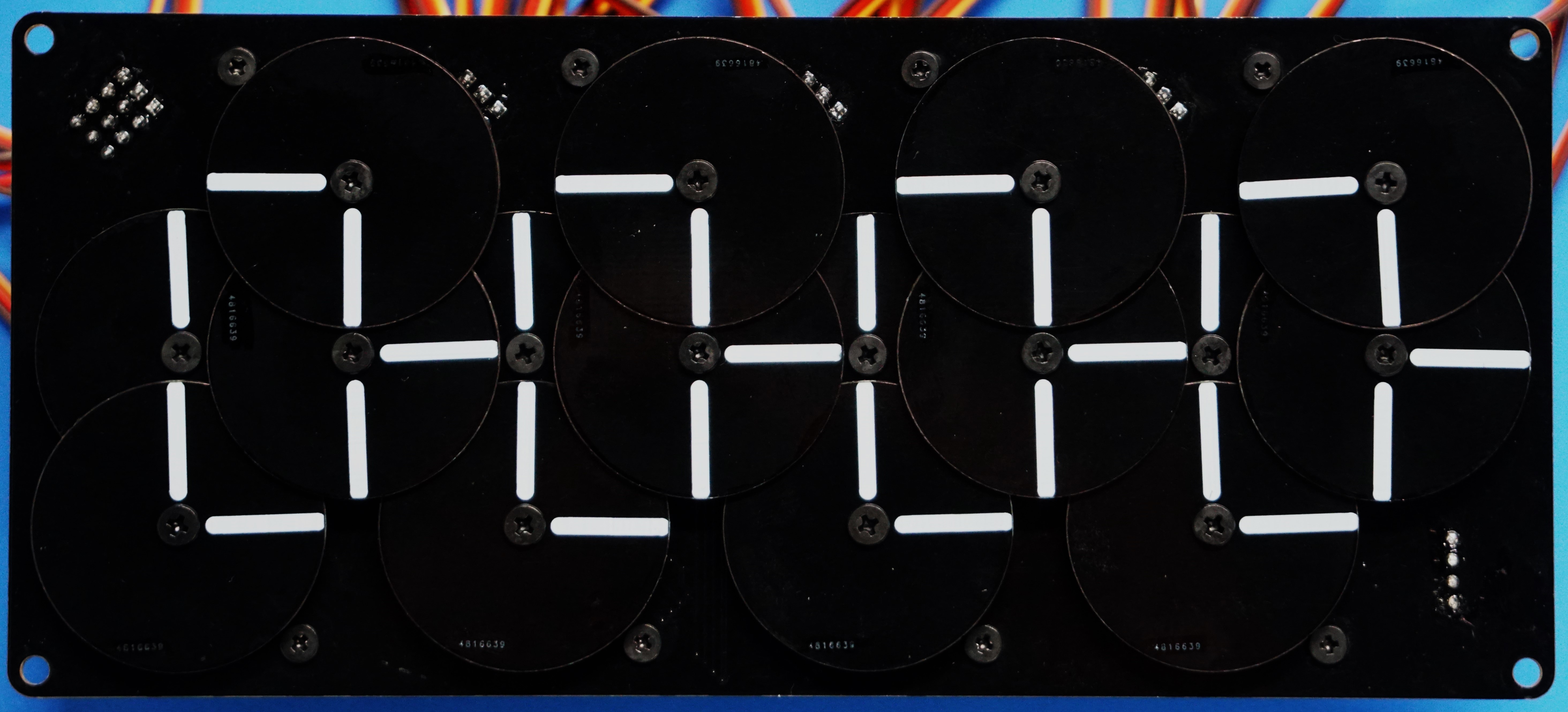
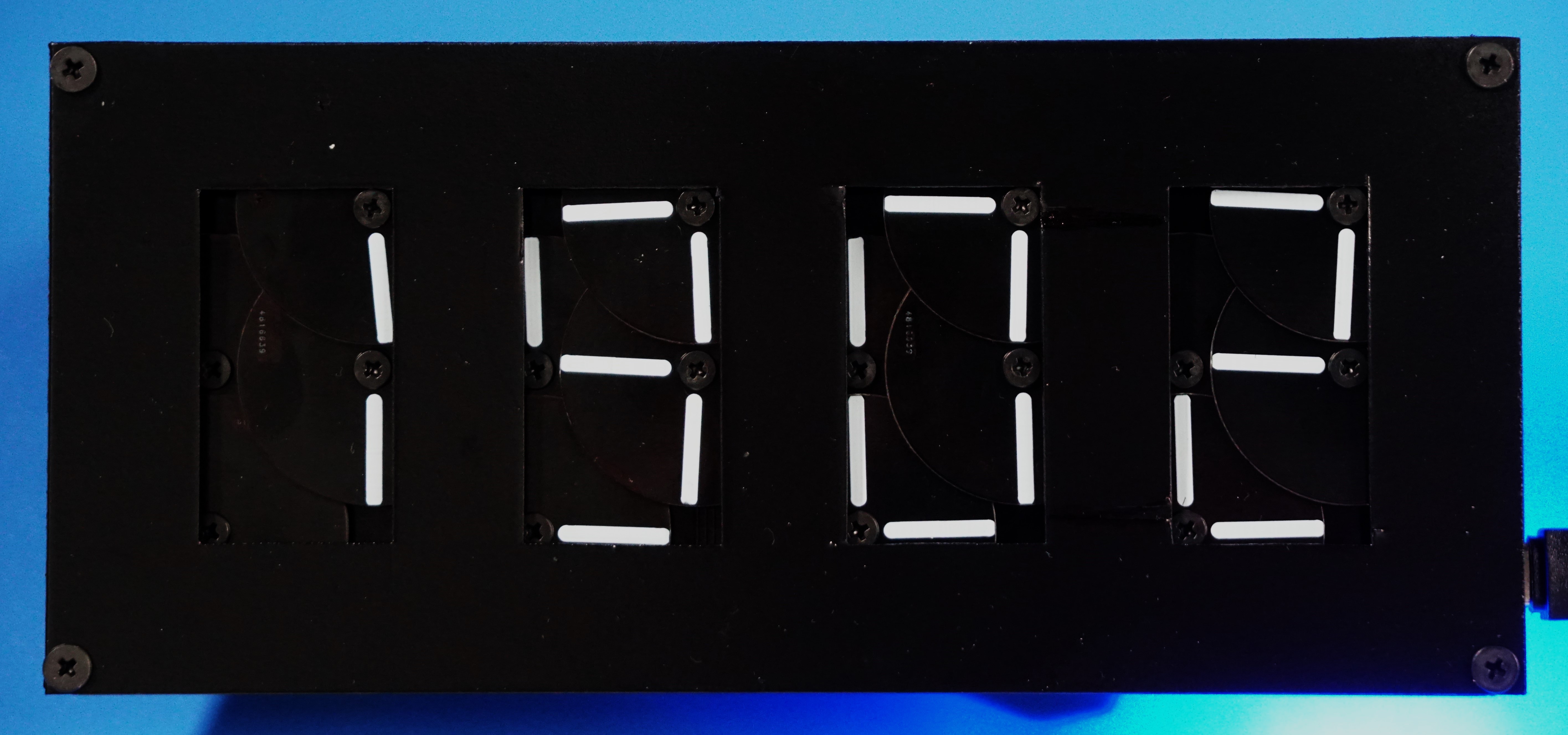
Display
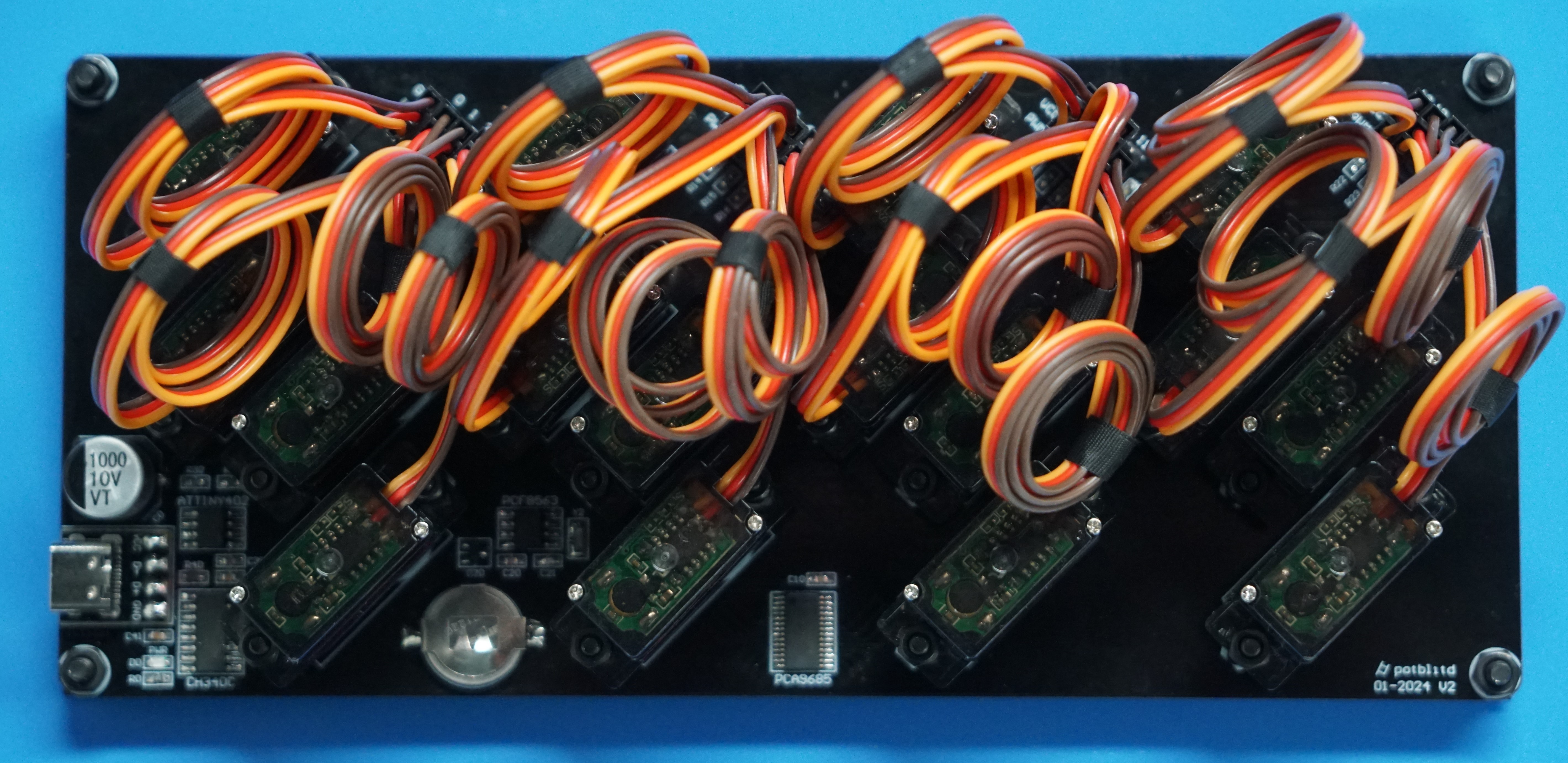
To create the smallest possible display, the servo motors are placed at 45 degree angle and in different directions. In this configuration, two digits must be separated by at least 20mm. The front plate hides the disks and segments outside of the actual display area.


PCB
The board not only integrates all the electronic components, but also includes the mounting holes for the servo motors. In this way, no additional mounting plates must be manufactured. The outline of the PCB is 80mm high by 180mm wide.

Mechanical parts
Since the PCB acts as the mounting plate, only the rotating disks and the front plate must be manufactured. The disks are actually made from thin PCBs with silkscreen segments as the thickness and material is very suitable. For the front plate, a 1mm PVC board was cut and painted black.
Assembly
All 16 servo motors are mounted to the base PCB with 9mm spacers and long screws. The precise mounting of the servos is crucial to avoid the rotating disks rubbing each other. With 0.8mm thick PCBs for the disks, they are overlaying each other through 1mm spacers, keeping the total height only a little over 5mm. The front plate is mounted on top of the base PCB with 6mm spacers in the corners.


Code
The code, written in Arduino, uses libraries PCA9685 and Rtc_Pcf8563. The PWM value for each disk position is established and then, the set_digit function defines the 4 disk positions for every number. With this function, the time fetched from the real-time clock can directly be set on the displays.

 danjovic
 Spencer
 opeRaptor
 alcor6502
not sure about "simpler", but it does show the 7-segment well isn't dry yet