Close
0%
0%

LED Oscilloscope Mk. II

Revamping a classic

Similar projects worth following
This is an update of a project I built in my youth - a real-time oscilloscope using an LED matrix display. Don't tell anyone, but it's really just a toy.

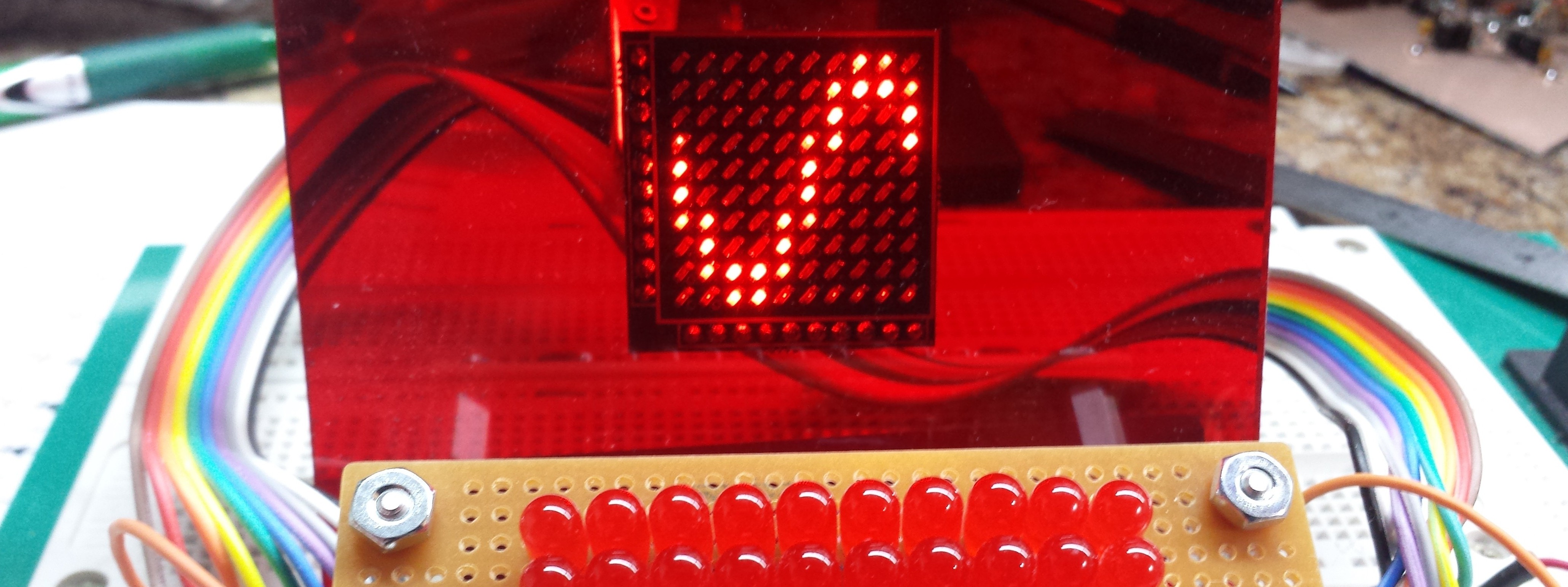
Around 1985 I built a 10x10 LED oscilloscope based on one of the Forrest M. Mims III designs. It used a CD4017 Johnson counter for the horizontal sweep and an LM3914 bar-graph driver for the vertical driver. The display was coarse, and I never measured the bandwidth, but it was OK for the audio tinkering I was into at the time - and was all I could afford.

Over the years, I've considered re-doing this design with faster components. LEDs can be driven pretty fast (laser diodes even faster if it comes to that), so the display shouldn't be the limiting factor. I've been playing with 74AC logic lately, and that coupled with a flash or pipelined ADC, I think could yield speeds of 80 MSps - theoretically enough to visualize up to 40 MHz signals. Realistically, you'd want more points per cycle - you'd get 10 samples/cycle at 8 MHz.

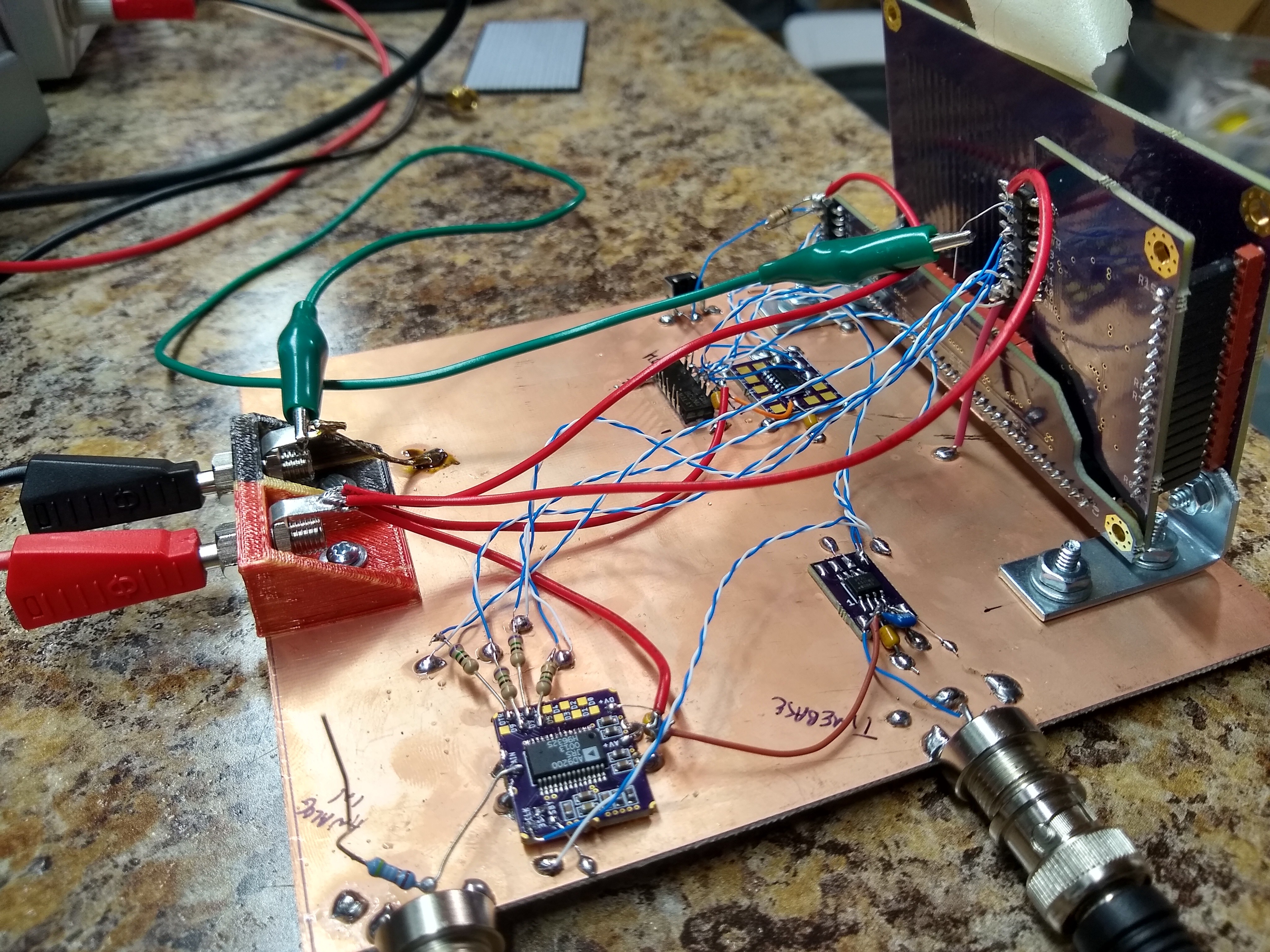
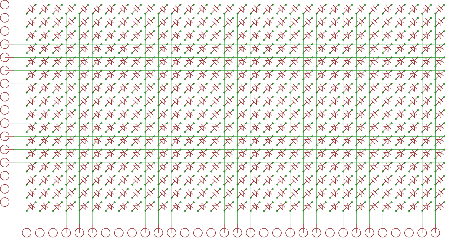
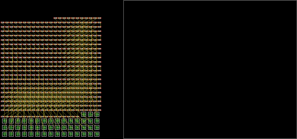
I haven't given much thought to the analog sections (front end and trigger) or the timebase yet, but have started playing with a design for the horizontal and vertical drivers. The basic initial design is detailed in the first build log.

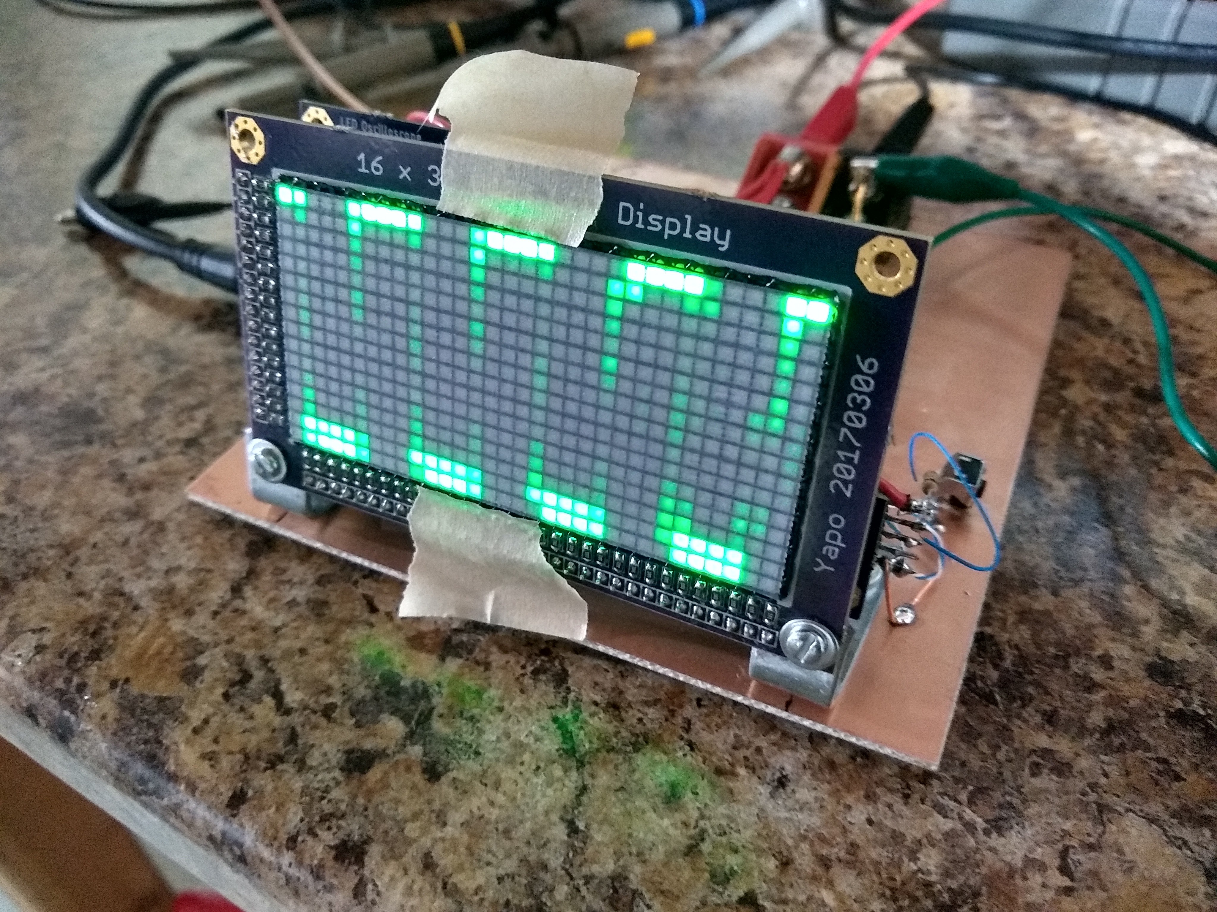
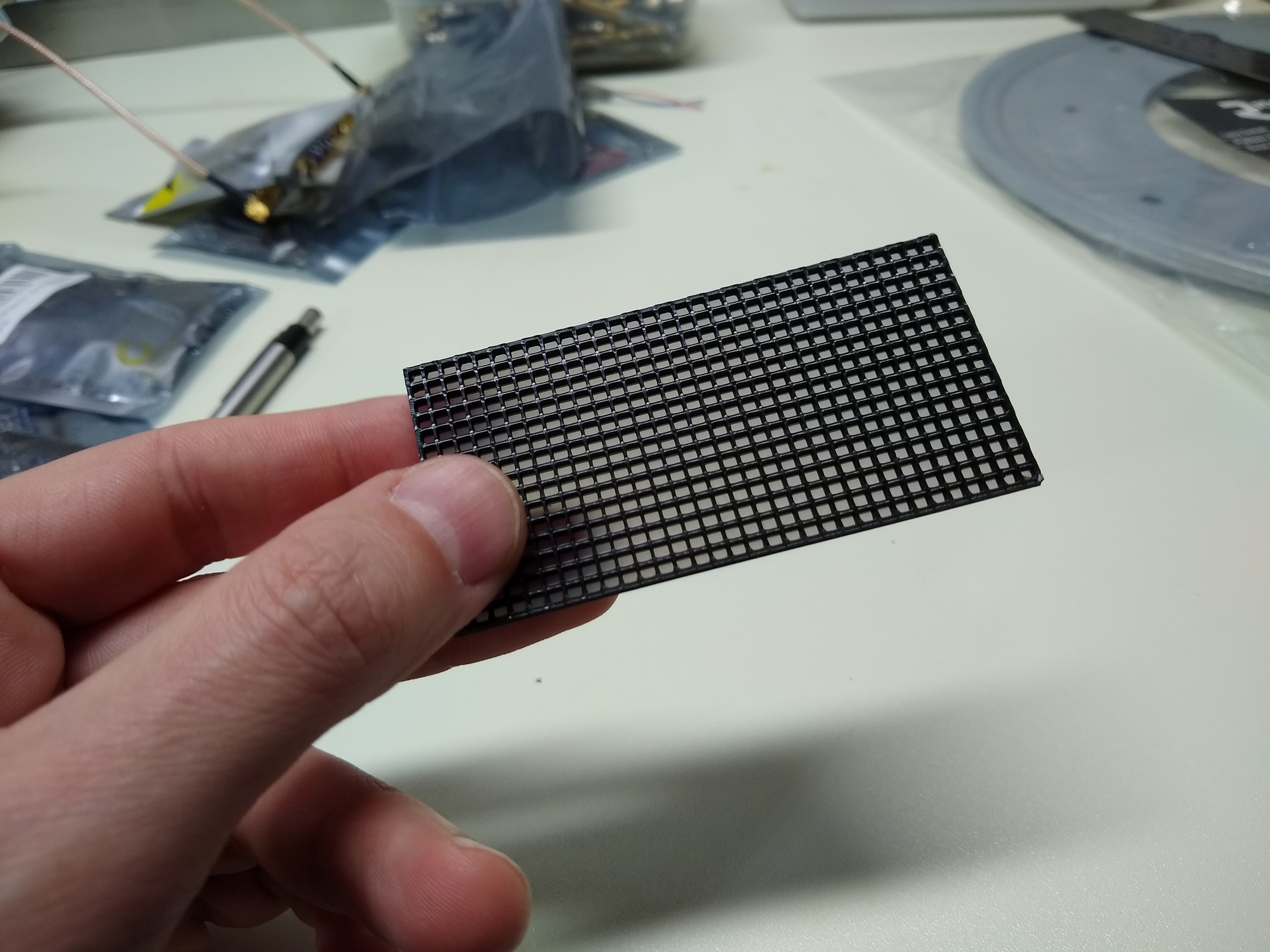
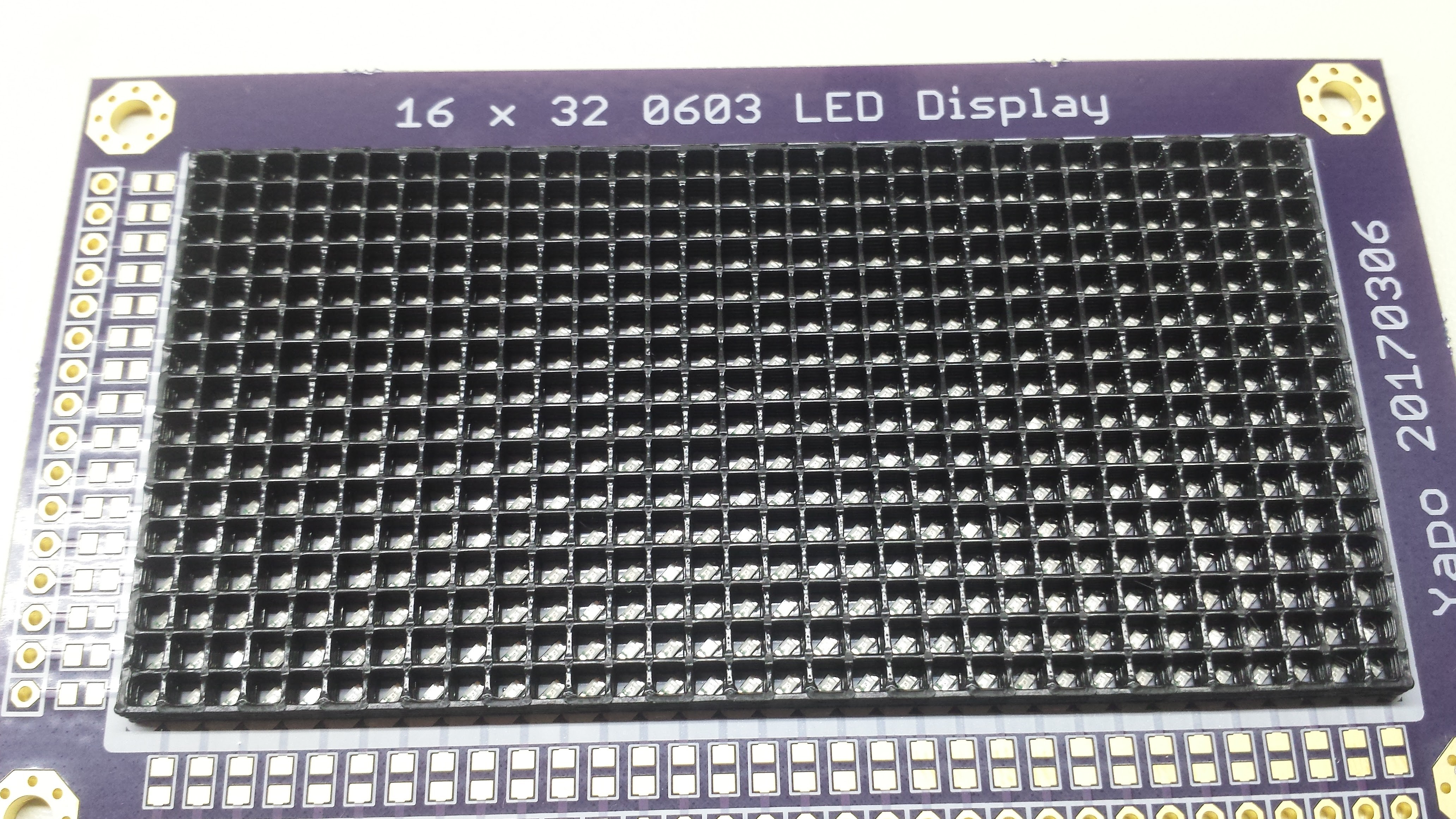
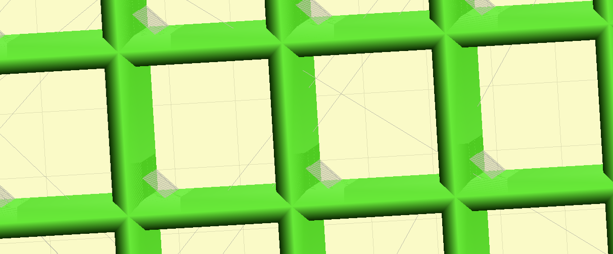
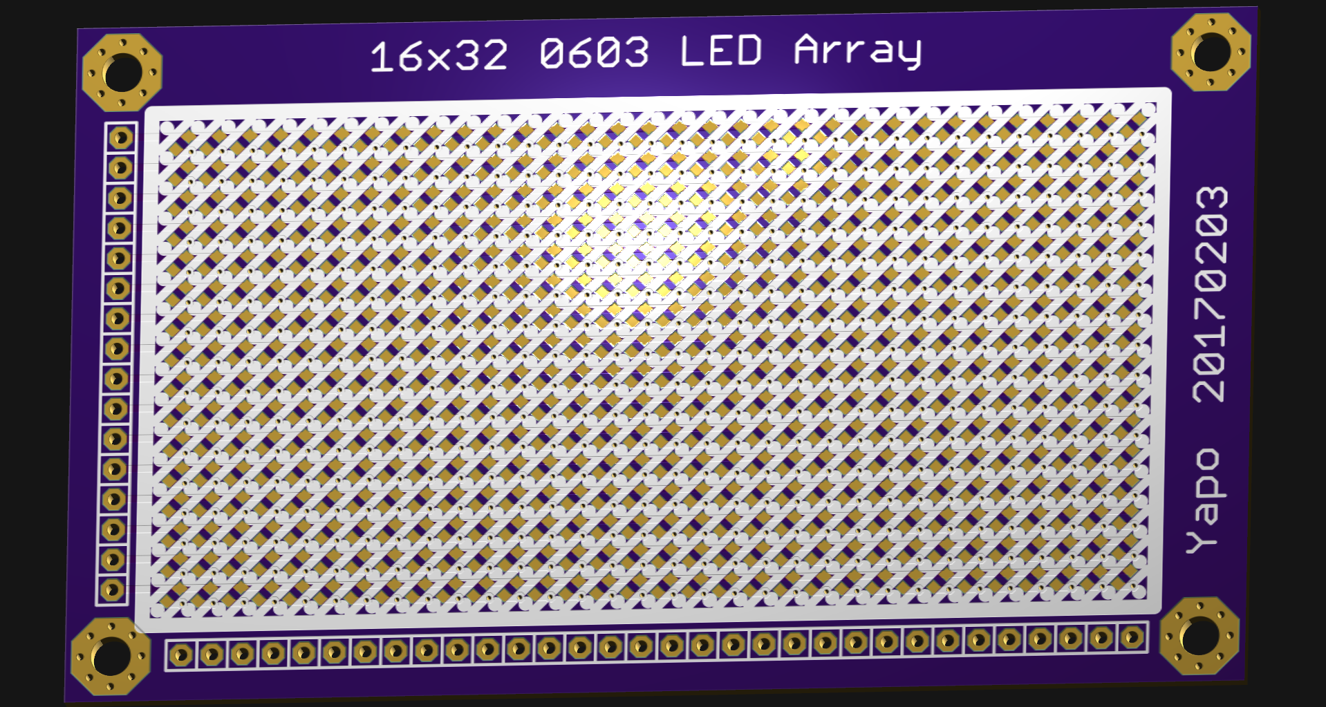
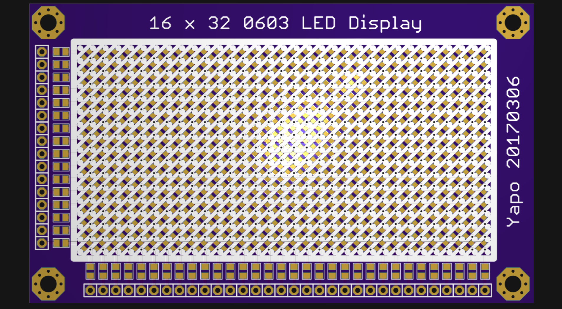
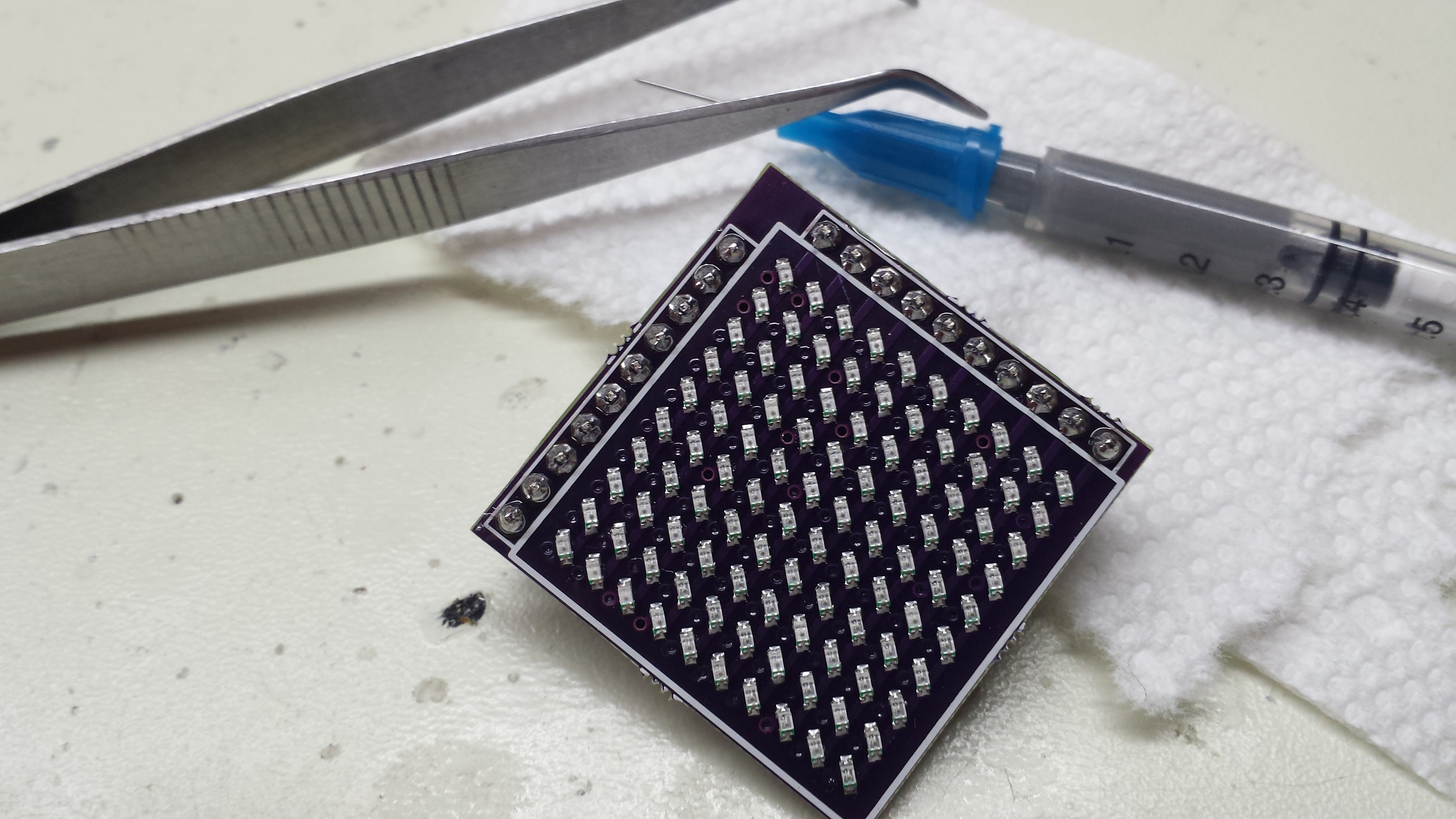
I also haven't chosen LEDs yet. My initial thought was to use ultraviolet LEDs and a phosphor screen for analog-scope-like persistence. I think instead, I'll make the screen connectorized so that I can try different LED matrices easily. I also want to test the LEDs for switching speed (with an avalanche photodiode detector) before committing to them. The whole project depends on the LEDs switching fast enough.

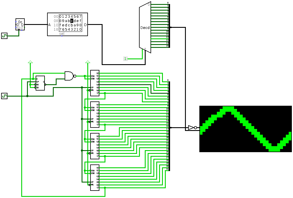
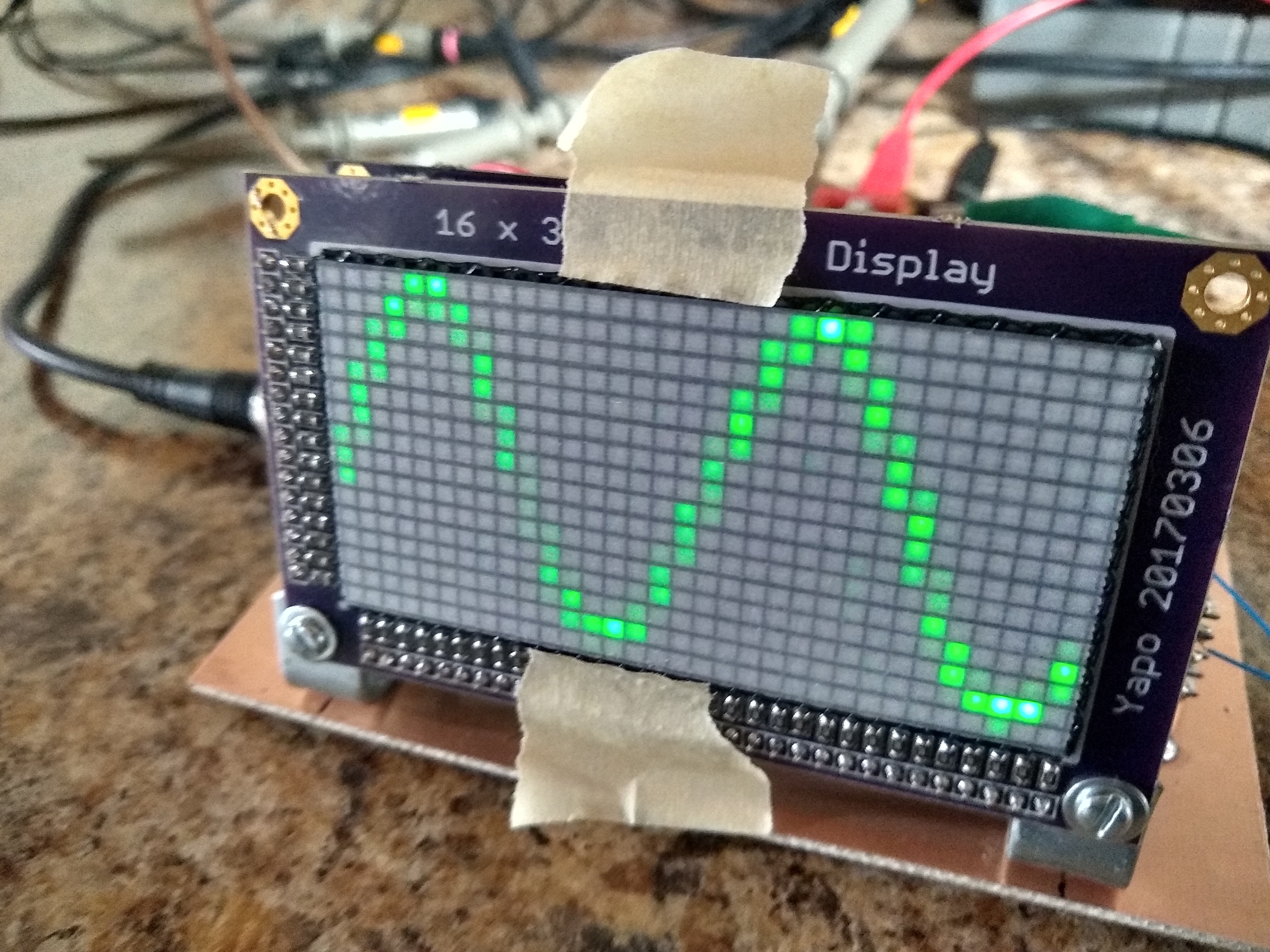
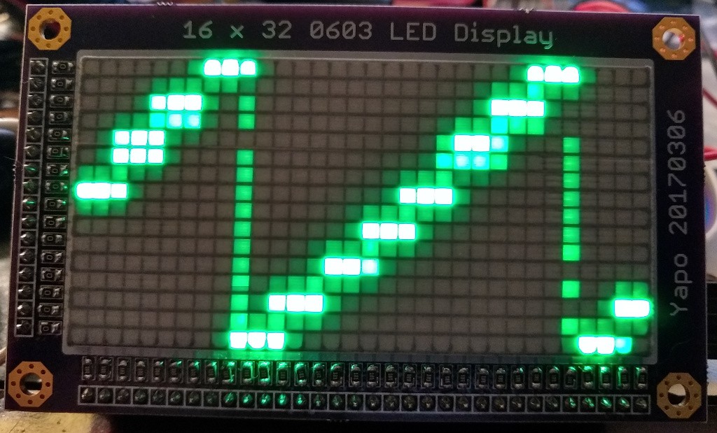
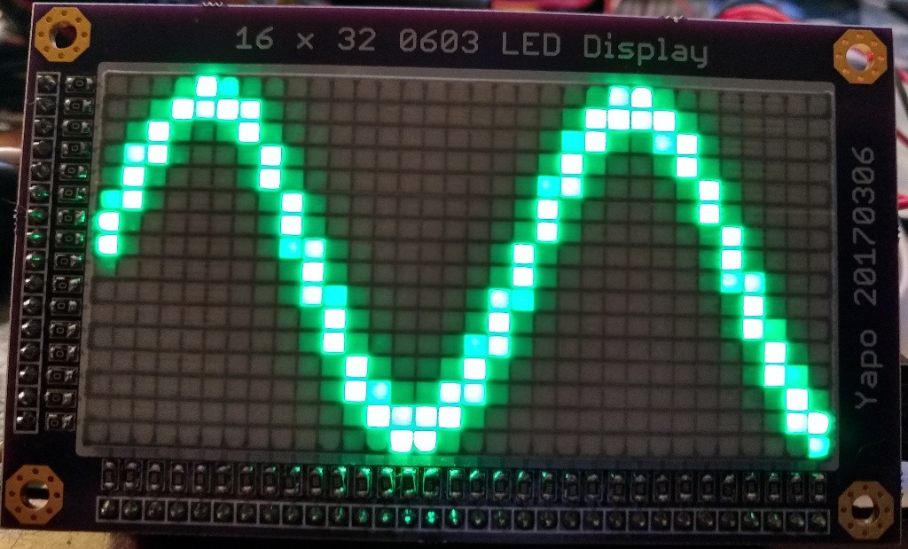
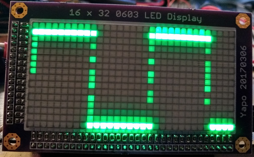
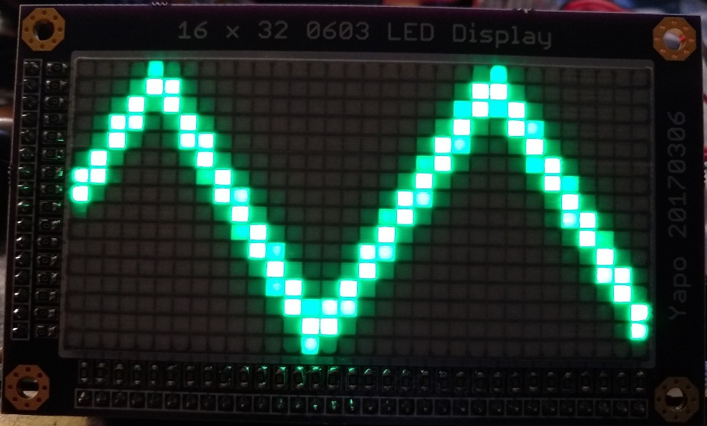
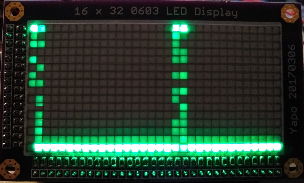
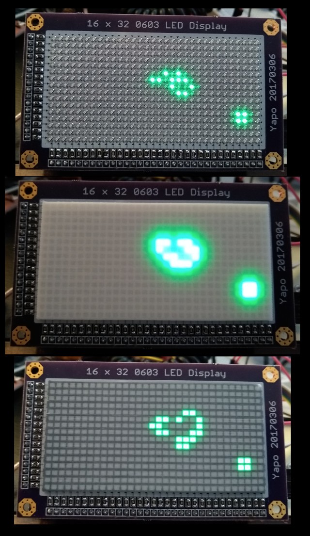
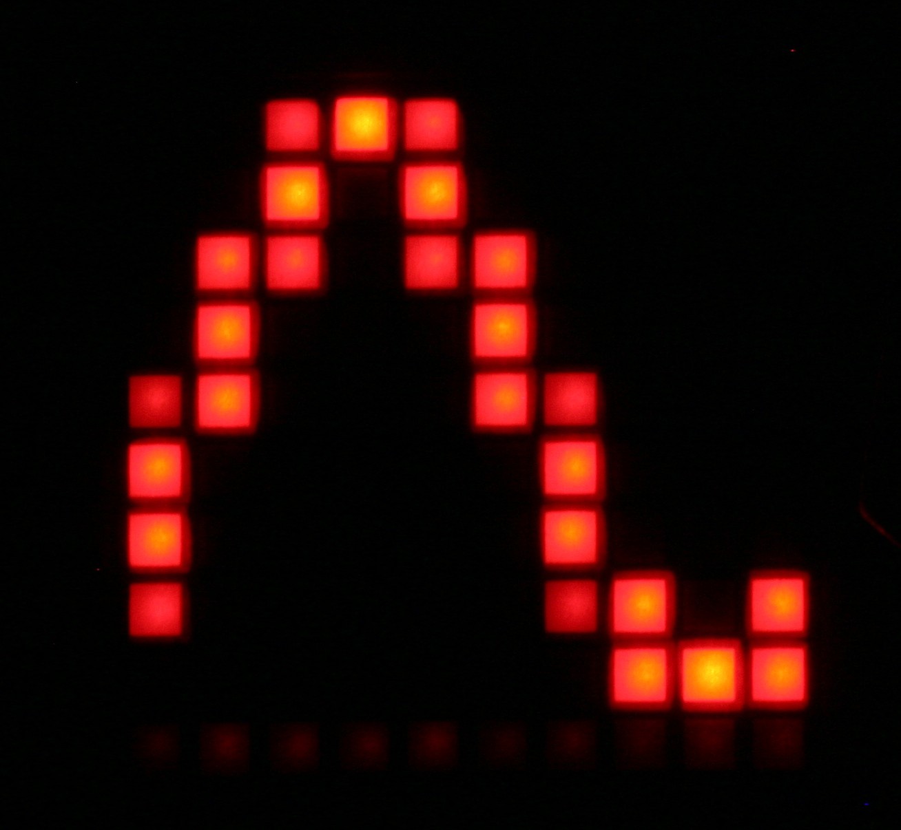
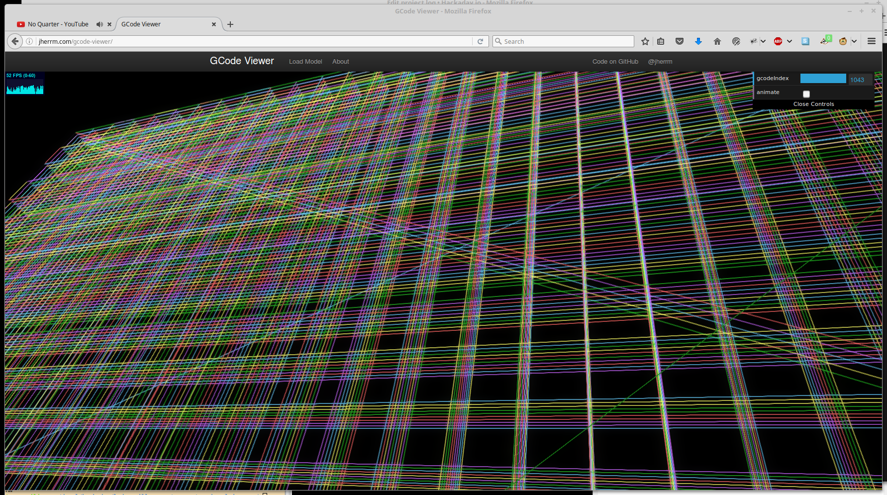
As for the display resolution, I haven't decided yet. I first thought about 32x32 (1024 LEDs), but then backed off to 16x32. I think I'm going to capture some waveforms on a modern digital scope and write a quick program to render them on a simulated LED matrix to see how it works at different resolutions.

I realize that a digital storage oscilloscope is probably not much more complex to design than the mess I'm creating here, but I really want to stay true to the original real-time scope concept. In case it's not obvious, this is not intended to be a practical oscilloscope design; for that, you'll have to look elsewhere.

first_sketch.pdf

First sketch of horizontal and vertical LED matrix drivers

Adobe Portable Document Format - 14.01 kB - 01/16/2017 at 20:47

Preview
Download

  • Blinking LEDs at 28 MHz

    Ted Yapo11/25/2018 at 05:52 6 comments

    So I wired up some 74AC logic to drive the horizontal board, and hooked up an AD9200 ADC to the vertical board.  I found that the maximum usable sampling rate was just under 30 MS/s, with good results at 28.  The limitation seems to be the speed of the LEDs and the matrix PCB itself.

    The AD9200 is in the lower left, with the top four bits (it's a 10-bit ADC) driving some 100-ohm twisted pair lines through source termination resistors (those wires were long enough to warrant it).  The input jack on the lower right is for the timebase signal - my DDS only goes to 25 MHz, so I added a x4 PLL on the prototype to see how far I could push things - that's the PLL in the SOIC-8 package.  At the top left, I have a 74AC74 and 74AC00 to cycle a single zero through the horizontal driver shift registers.

    The AD9200 datasheet specifies a maximum rate of 20MS/s, but I found it produced good results for the upper 4 bits (all I care about) out past 30 MS/s.

    I simulated the thing in logisim before building it just to be safe.  It turns out that logisim has an LED matrix component, so I could actually simulate it pretty well:

    The bottom part is the horizontal driver - four 74AC164 shift registers that reside on the horizontal driver PCB.  The flip-flop and NAND gate are dead-bugged on the copper clad.  I made 512 mistakes when I populated the LEDS - they're all backwards, so I had to mess around with the drivers a bit.  For instance, the horizontal shift register requires a single low output to ripple through the register, which complicates the logic. When I assemble an LED matrix correctly, this will be much easier.

    This also would have been easier with an FPGA, but then there's the 3/5V problem.  I have a bunch of GAL16V8's around, but I just couldn't go *that* old-school...

    The top part of the simulation stands in for the ADC - it's just a counter, RAM, and decoder with a stored triangle waveform.

    It works on the hardware, too.  Here's a 1.69 MHz sine wave sampled at 28 MS/s.

    At this sampling rate, the display is pretty dim.  In fact, it only has full brightness below around 2 MS/s.  At higher sampling rates, the display becomes progressively dimmer.  It's not really surprising - at 28MS/s, those LEDs are blinking at 28MHz!  Between the PCB layout and the capacitance of the LEDs themselves, there's a limit to how fast they can blink.  I wanted to see how far you could push the original concept, and this is probably it!  You might get it to go a little faster with a better PCB layout or maybe better choice of LEDs, but this is probably pretty close.

    I avoided the whole issue of triggering the sweep by 1) making the sweep free-running, and 2) driving both the horizontal timebase and the analog input from two channels on the same DDS generator, so they are always in phase.  This makes things a lot easier to test.  To make a usable oscilloscope, you'd need to add some triggering mechanism.  I have plenty of ideas here, and have simulated some promising solutions, but we'll have to see how well they work on the bench.

    I didn't even try to measure it, but I'm sure this thing is an emissions nightmare.  I tried all sorts of sampling frequencies between 1 and 30 MHz tonight, and frankly I'm a bit surprised there is not a mob of angry ham radio operators knocking at my door with torches and pitchforks.

    I have to admit, I'm a bit disappointed that the LEDs are the limiting factor.  I'll have to think about it a little more.

    I can't resist one more image that I think really shows how this project is different from a traditional digital scope.

    It's got none of that dead every-pixel-the-same look of a digital scope.  Instead, it has more of the softer feel of a CRT.

  • First waveforms

    Ted Yapo11/23/2018 at 02:49 0 comments

    While I had an arduino hooked up to the display, I couldn't resist using the ADC to make a software version of the scope.  It boasts an ultra-fast sampling rate of 77ksps :-), but is good enough to see how waveforms will look.  The result definitely has an analog scope feel - not like the "dead" waveforms on a digital scope at all.  I like it a lot.

    All of the input waveforms were at 3kHz.  First up, the staircase.  I hooked the output of my DDS to the ADC input pin.  This is the default waveform stored in the Arb. memory.  Doesn't look that bad.  That's not all light bleeding - there's some trigger jitter involved, too - more about that below.

    Here's the sine:

    The square wave:

    The triangle:

    and finally the 20us pulse:

    The LEDs turned on in the "vertical lines" are constantly changing, due mostly to trigger jitter.  You do get a sense of what's going on while viewing it live, but my camera can't capture a good video of it - sampling issues at work.

    The meat of the code is this simple loop:

    void scope()
    {
      noInterrupts();
      digitalWrite(OEbar, HIGH);
      digitalWrite(PWMbar, LOW);
      while(1){
        uint8_t triggered = 0;
        int val, old_val = analogRead(INPUT_PIN);    
        while (!triggered){
          val = analogRead(INPUT_PIN);
          if (val >= 512 && old_val < 512) triggered = 1;
          old_val = val;
        }
        PORTD = PORTD & (0xff - (1<<DAT)); // digitalWrite(DAT, LOW);
        for (uint8_t col=32; col>0; col--){
          PORTB = (PORTB & 0xf0) | (val>>6);
          PORTD |= (1<<CP); //digitalWrite(CP, HIGH);
          PORTD &= (0xff - (1<<OEbar)); //digitalWrite(OEbar, LOW);
          val = analogRead(INPUT_PIN);
          PORTD = (PORTD & (0xff - (1<<CP))) | (1<<OEbar) | (1<<DAT);
        }
      }
    }
    

    It samples the ADC in a tight loop, looking for the trigger condition - in this case, when the waveform crosses mid-level.  Then, it samples the ADC 32 times, displaying each value as the appropriate LED in that column.  There's no way to calibrate the timebase (I guess you could make it go slower if you wanted), and overall the approach is pretty limited.

    One thing I learned, though, is that I really don't want to trigger digitally on the output of an ADC - this causes too much jitter.  It might be OK if the ADC is running much faster than the sweep, but I think a better approach is a fast comparator circuit.

    Starting the sweep exactly on the comparator output is another problem...

    Anyway, I think the display shows promise.  Now I just have to get it sampling at 20 MHz or so for a real  test.

  • Purely printed bezels

    Ted Yapo11/21/2018 at 20:58 5 comments

    I spent some time playing around with 3D printed bezels again - this time, printing the diffuser as well as the bezel.  You can see the results: no bezel/diffuser (top), white bezel/white diffuser (middle), black bezel/white diffuser (bottom).  You lose some brightness with the black bezel, but the overall effect is much better because it really kills the light bleeding.

    The diffuser is a single layer of 0.2mm white PLA+.  The bezel (square cells) is printed directly on top of the diffuser layer.  For white/white, it's just a single print, but to get the black bezel on a white diffuser, I had to make two separate-gcode files, and swap filament in between printing them.  It's a little bit of a pain, but the result works pretty well.

    Here, I'm purging any white filament from the hotend after printing the diffuser layer and loading the black filament:

    Next, I run the bezel g-code to construct the cells right on top of the diffuser:

    The result is a single piece which fits over the 0603 LEDs (on 0.1" centers):

    Like the previous experiments with 3D printed bezels at this scale, normal slicers just don't cut it :-) I had to generate the g-code to print these using a python program.  After you get started, though, it's pretty cool what you can do by putting down a few hundred microns of plastic exactly where you want it.

    I think I'm going to expand the code to add brackets to mount the bezel to the PCB holes.  More python -> more g-code -> more melted plastic.

  • Ultra-low-def Video

    Ted Yapo11/21/2018 at 05:51 2 comments

    I threw together a quick test of video on the LED screen.  It's not great, but then again, it's only a 0.000512 megapixel display!

    This was an ugly hack.  A python program on a PC uses opencv to read video frames from a webcam, resize them to 32x24, then transmit the upper 16 rows of the image over a serial port at 1M baud.  On the other end, an arduino nano collects the data into one of two ping-pong buffers while the other buffer is displayed on the LEDs.

    With a diffusing screen, the video looks better to the eye, but on camera, the raw LEDs look better (although a little sparse).

    I might be done with display tricks at this point.  Maybe.

  • Bringing project back to life

    Ted Yapo11/20/2018 at 04:18 2 comments

    Conway's Game of Life, actually...

    I dug the display board and the horizontal and vertical driver boards out of a box of junk to revive this long-dormant project.  I also realized I never documented the driver boards - I'll have to do that next.

    Anyway, I had some fun tonight driving the display with an arduino nano instead of the FPGA I'll use for the oscilloscope mode.  Beyond the basic light every pixel and draw some diagonal lines, I wanted something interesting to watch, and this was the first thing to come to mind.

  • Better bezels through g-code

    Ted Yapo02/22/2017 at 04:46 0 comments

    I couldn't get Slic3r to generate really nice segmented bezels at this scale, so I wrote a python program to generate g-code commands to send to a 3D printer directly. As a result, I can make cells with exact 1-extrusion-thick walls and minimal blobbing. The code is checked into the GitHub repo, but you might need to tweak it to match your printer/filament settings - oh, and be prepared to yank the plug if you got anything wrong :-) Here's the result:

    This display uses the new 3D printed bezel, the Rosolux 116 tough white diffuser, Roscolux 26 red filter, then a black mask laser printed on overhead transparency stock. At some point I will gather enough courage to run the Roscolux sheets directly through the laser printer and see what happens - they are intended for theatrical lighting, so are heat-resistant, but I'd hate to screw up a laser printer. No guts no glory, I guess (but also no goop in my printer). I suspect printing directly on the diffuser or red filter (or both) might fix some of the bleeding around the pixels.

    The python code is pretty simple; it just generates a grid of 1-extrusion wide cells. For the printer I used, this means 0.42 mm wide walls. The code uses alternating zigzag patterns in the horizontal and vertical. Even though there is theoretically twice as much material deposited at each corner, this doesn't produce too much of a blob. You might be able to improve this by slowing the extrusion right at the corners, but I'm not sure if that will introduce other issues.

    The output of this program can be sent directly to the printer, which is a little scary. I have a kill switch on the power supply from previous experiments like this. I didn't need it this time, but maybe I just got lucky. One way to be safer with this kind of thing is to use a g-code previewer. There are a few on the web - I've started to like this one, which rendered this preview of the 16x32 bezel:

    Here's the printed result for the 16x32. I still haven't built anything to drive the display yet :-)

    EDIT:

    I'm going to try putting a sheet of the diffusing material on the 3D printer bed to see if I can get the bezel printed directly on to it. That might work out really well...

  • I'm going to feel this in the morning

    Ted Yapo02/20/2017 at 03:38 12 comments

    The 16x32 display boards arrived yesterday from OSH Park. I spent some quality time at the bench this evening.

    The LEDs all work, although they got mounted with the wrong polarity - I got the first one wrong, and was very consistent after that. It will take a few inverters to make this work with the original circuit idea, but that's easier than re-working the board :-)

    The really scary thought is that I have 2 more PCBs like this one.

  • Filter Madness

    Ted Yapo02/04/2017 at 20:42 4 comments

    I've been playing with filtering the display for contrast and filling the space between pixels.Here's how the display looks without any covering, with a 0.15" thick bezel, and with the bezel plus a 116 Tough White Diffusion and 26 Light Red filter.

    Out of all the many combinations I've tried, I like this last one the best. You lose some light, but the LEDs are really beginning to look like pixels. In the photo, the filters aren't held tightly against the bezel, either, which improves the display a bit. I think the final assembly will need a thin acrylic sheet over the top for protection and to hold the filters flat against the bezel.

    I love Roscolux filters - they're made for theatrical and cinematic lighting, but are very useful for general optical hacking. They're relatively inexpensive, come in hundreds of shades, and you can get a free swatchbook full of samples if you go to a theatrical supply store (you might end up having to pay for one online). Once you determine the ones you want, you can order them in big rolls. I found a few dozen useful ones for diffusing and filtering the red LED prototype display in the pack:

    Also shown are the 3D printed bezels with a square hole for each LED.

    There are two issues I'm still working on. First, there is a significant amount of light lost. I think I can regain some by adding a white silkscreen covering the PCB, and using a white bezel (currently printed in black). I will try printing the bezel in white, but I wonder if it will allow leakage from neighboring pixels. If all else fails, I'll try painting the black bezel white - that should block light from adjacent LEDs while reflecting more of the center pixel.

    The second issue are those annoying dark corners in each pixel cell. Printing this bezel is just at the edge of what's possible with my printing setup - each wall in the grid is only one extrusion wide. Unfortunately, the slicer isn't doing a great job of path planning, and the print head makes a little jog in the corner of each cell. You can see it here in the gray lines:

    Those gray lines are moves (without extruding material), but the extrusion doesn't stop on a dime, and a little string of filament ends up in those corners - enough to cause those distracting dark corners seen above. You might be able to clear them out with a hobby knife, but I don't think that's practical for larger displays.

    I'll play a little more with the printing toolchain, then I might try writing g-code for this bezel directly. I wrote a package a few years ago for 3D printing from Javascript, so I don't think it would be that difficult. For an object like this, the imprecision of triangular modeling and subsequent slicing starts to outweigh the convenience, and custom-written g-code to print the grid might work a lot better. In that case, you have complete control of the path of the print head, and can keep it from making those silly corners.

    Another possibility would be to design the grid with semi-octagon cells, which intentionally have four dark corners. It might be that those can be printed consistently. But, I really would like edge-to-edge square pixels...

  • 16x32 Display Design

    Ted Yapo02/03/2017 at 18:28 12 comments

    UPDATE 20170207: I forgot resistors! Fixed in the addendum below.


    I painstakingly drew the schematic for 512 LEDs in this display, then endured the drudgery of laying out the board. The whole process took about 45 seconds. Yes, I wrote a few Eagle User Language Programs (ULPs) (elapsed time after the scripts were written and debugged). The previous time I wrote one was last century to lay out a circular LED clock face. I figured it was about time I regained those skills. The code is here on GitHub. You can edit the scripts to produce any size array. The "led_matrix_schematic.ulp" code generates the schematic. Here's the 16x32:

    The default board (auto-generated by Eagle) looks like this:

    A second script ("led_matrix_layout.ulp") re-arranges all the components and adds traces, vias, and silkscreen programatically:

    The silkscreen matrix is there to act as a reflector. I have been experimenting with 3D printed segmented bezels and diffusers which make the 0.1"-spaced tiny-die LEDs look like a closely-packed array of pixels. I'm still experimenting with a number of different diffusers from a Roscolux theatrical lighting gel swatchbook - I'll post images in an upcoming log. The short story is that you can make these matrix displays look like a nice pixel array, but at the cost of some efficiency. I think that using the silkscreen to reflect light off the board will improve the brightness - and it's free, so why not. There's a flag at the top of the script to turn off all the reflector silkscreen segments if you don't care for them.

    The scripts rely on an Eagle library ("led_matrix.lbr" - also in the GitHub repo) I created that contains only three parts: the 0603 LED, a 1-pin 0.025" header, and a #4-40 or (M3) mounting hole. You need to add this library to your project before running either script. The mounting holes aren't automatically placed, so you'll have to do those manually, as well as sizing the board and adding any desired text.

    If you run this script, you may be concerned to find "unrouted" airwires on the board (shown below).

    The problem is that I can't figure out how to programatically "route" nets to Eagle's satisfaction. Instead, I draw traces on the appropriate layers. In some cases Eagle recognizes the electrical connection, and in other's it doesn't. Part of the problem is that the LED package is metric, while the board is in inches. Add to that the irrationality of rotating the LEDs 45 degrees, and the imprecision of floating point representation, and it's not surprising that Eagle loses track of things. If this concerns you, you can verify for yourself that all the tracks are in order.

    If you make one of these boards, you will also want to adjust your design rules to "tent" the vias - cover them with soldermask. This should enable them to carry the silkscreen, too.

    Here's a rendering of the final test board. I am going to wait a day before sending this out just in case I think of anything. I usually do.

    ADDENDUM

    I forgot to include resistors on the board - I'm glad I waited to send this one out! I just updated the GitHub repo with code that adds 0805 resistors in each row and column. At low speeds, you really only need one or the other, but I am planning to use both on higher-speed versions to damp ringing on the row and column lines. It's not really possible to maintain a controlled impedance on the lines, and I'm concerned that any ringing may end up visible as ghosting on the LEDs. By splitting the required dropping resistance across the row and column lines, I may be able to hide these effects.

    Now I'll send it. Sent!

    In the two weeks before the boards return, I can look at fast sweep generation with 74AC164's and some simple ADC tests with an AD9200 ADC (because I happen to have about a hundred of them lying around).

  • 10x10 0603 Display

    Ted Yapo01/31/2017 at 03:13 5 comments

    The PCBs arrived today from OSH Park, and I had the opportunity to populate one after dinner.

    It works, and it is smaller, but there were two things I don't like about this display. First is the extra space between LEDs; I think it's distracting. I am considering:

    1. Decreasing the space between LEDs (which may make it more difficult to populate the board
    2. 3D printing some kind of bezel to be used with a sheet of ground glass (or equivalent) to fake closely-packed pixels

    I also found the contrast lacking, so I added a sheet of standard #2423 colored acrylic, which I've used on other projects for LED contrast filters. This helps a lot.

    I've seen some really tiny LED matrix displays on hackaday.io - how close can people get the LEDs reliably? Mine are on 100 mil centers.

    I applied solder paste with a 1 ml syringe and 25 ga blunt needle, then placed the LEDs with tweezers. The whole assembly took less than an hour, including several magnified checks before skillet reflowing the board to make sure none were on backwards. I applied a little too much paste, which caused some solder balls to form, so I spent ten minutes prying them out of the flux with a dental pick.

    As with the previous display, it looks better in motion:

    I have two boards left, and some green and UV LEDs to try. I picked up cans of fluorescent green and glow-in-the-dark spray paint to experiment with making a phosphor screen for the UV LEDs. I'd really like to see if I can simulate the feel of an analog scope screen.

    I also figured that I probably couldn't do a 32x32 array in one sitting. 100 was easy enough, and I might be able to do 200 at once with minimal fatigue, but then I'd have to take a break. I'll probably paste-and-populate 200 or so each day for a week or so, then reflow the board. That might be difficult to do with a stencil, but with a syringe, I can take a while to get all the parts on there.

View all 13 project logs

Enjoy this project?

Share

Discussions

ekaggrat singh kalsi wrote 01/08/2019 at 10:37 point

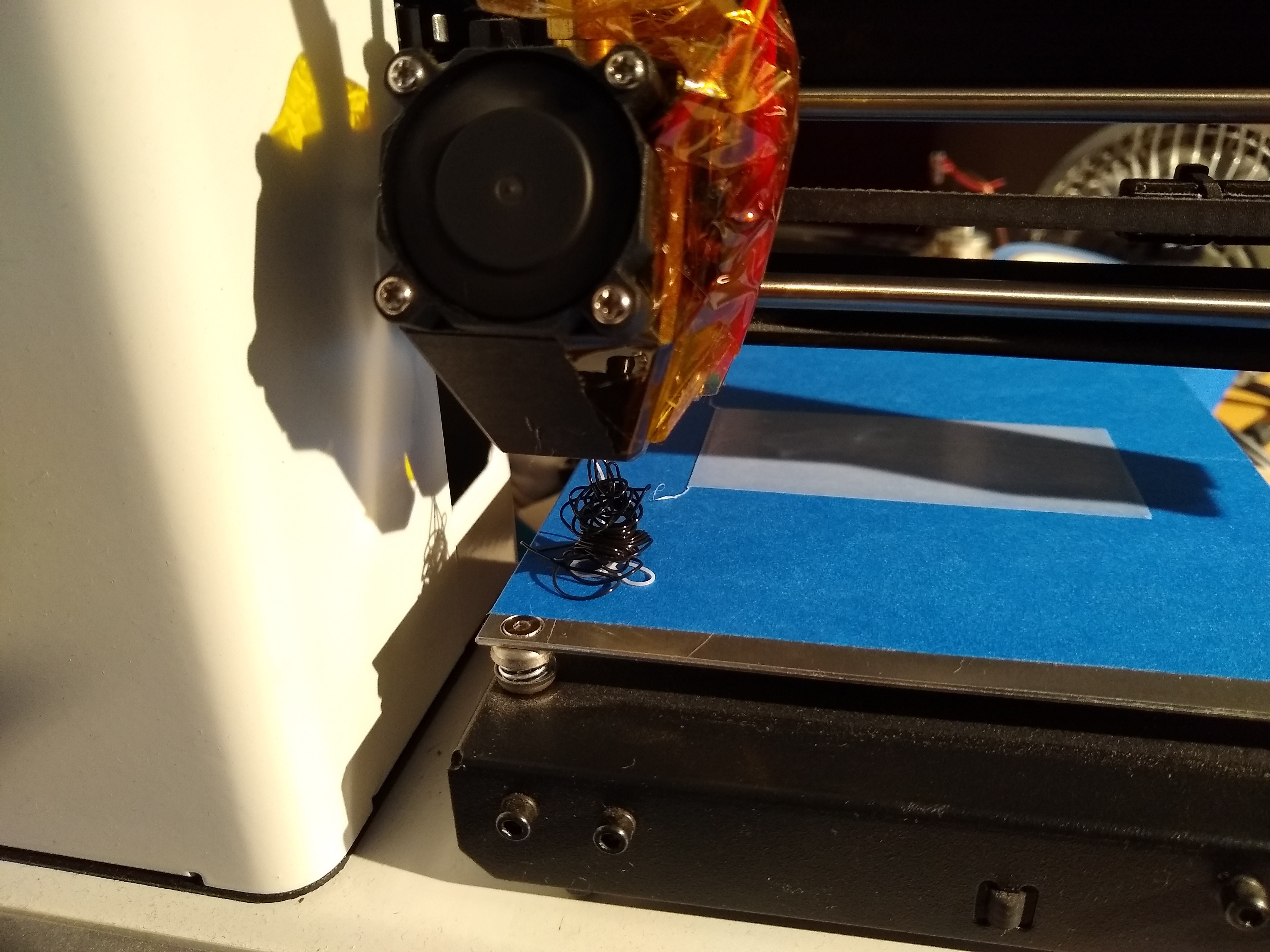
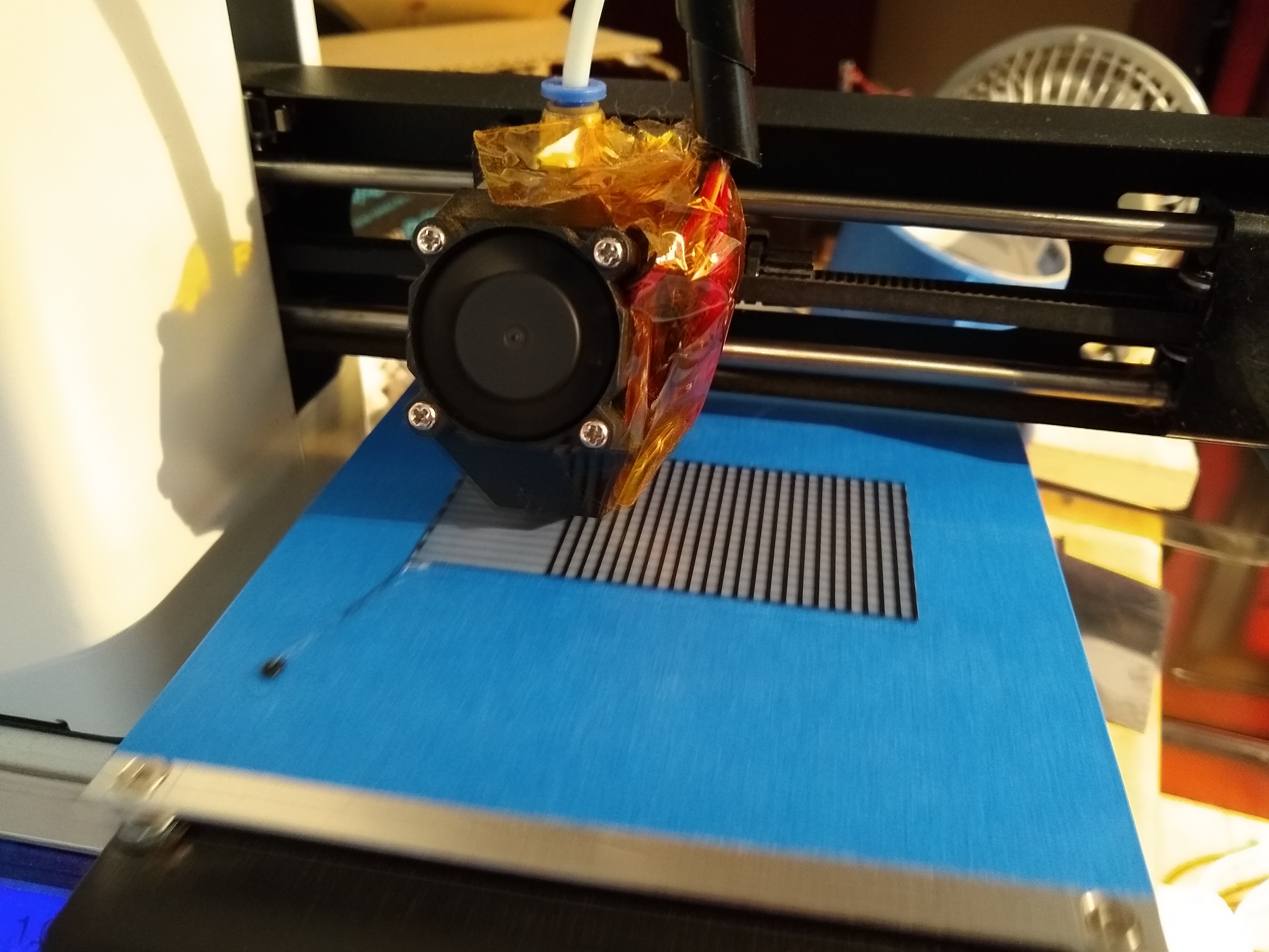
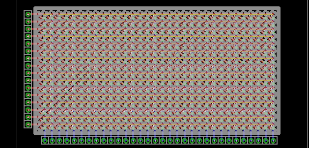
how did you place the leds so perfectly?

  Are you sure? yes | no

zakqwy wrote 02/20/2017 at 18:24 point

Just noticed your bit in the description about a phosphor display and UV LEDs. Last year I bought a sheet of PhosphorTech material -- it's the yellow stuff that is used in conjunction with blue LEDs to make them white (in this case, ~5500 K). I haven't done much with it beyond putz around, so I'd be happy to donate a 2"x4" (or whatever size you need, within reason) bit to the project. You should be able to use one of your spare 16x32 boards, just swap the red LEDs for blue. Could make a pretty neat effect. Yay more soldering!

  Are you sure? yes | no

Ted Yapo wrote 02/20/2017 at 18:52 point

Thanks!  I might take you up on that.

I have soldered up a 10x10 array of 0603 UV LEDs as a test, and have been playing with various screens, but haven't written it up yet.  I've been experimenting with screens laser-printed on transparency material, then spray-painted with glow-in-the-dark spray paint.  The results aren't great so far because the "normal" paint has very few phosphor particles in a clear carrier - the result looks very grainy.  I have to pick up a can of the "premium" paint, which costs twice as much, but I suspect uses a higher concentration of active material.

Is the PhosphorTech material fluorescent or phosphorescent?  I've tried some purely fluorescent material, and they do a good job of down-converting the UV to visible, but turn off as soon as the LEDs do, with no persistence. Ideally, I could find some medium-persistence phosphor like used on the face of a CRT oscilloscope.

I have some activated ZnS powder, too, from spinthariscope experiments, but it's opaque to visible light, so you'd need a very thin layer of it to make a screen.  This may be the problem the spray paint manufacturers are facing.

  Are you sure? yes | no

zakqwy wrote 02/20/2017 at 19:01 point

It's phosphorescent, but I'm not sure what kind of persistence it offers -- probably worthy of some experimentation. This is the datasheet of the stuff I have: https://secure40.securewebsession.com/2nc99ci87.site.aplus.net/data_sheets/RadiantFlex Online Datasheet.pdf

  Are you sure? yes | no

Similar Projects

Does this project spark your interest?

Become a member to follow this project and never miss any updates