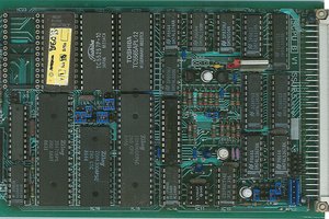
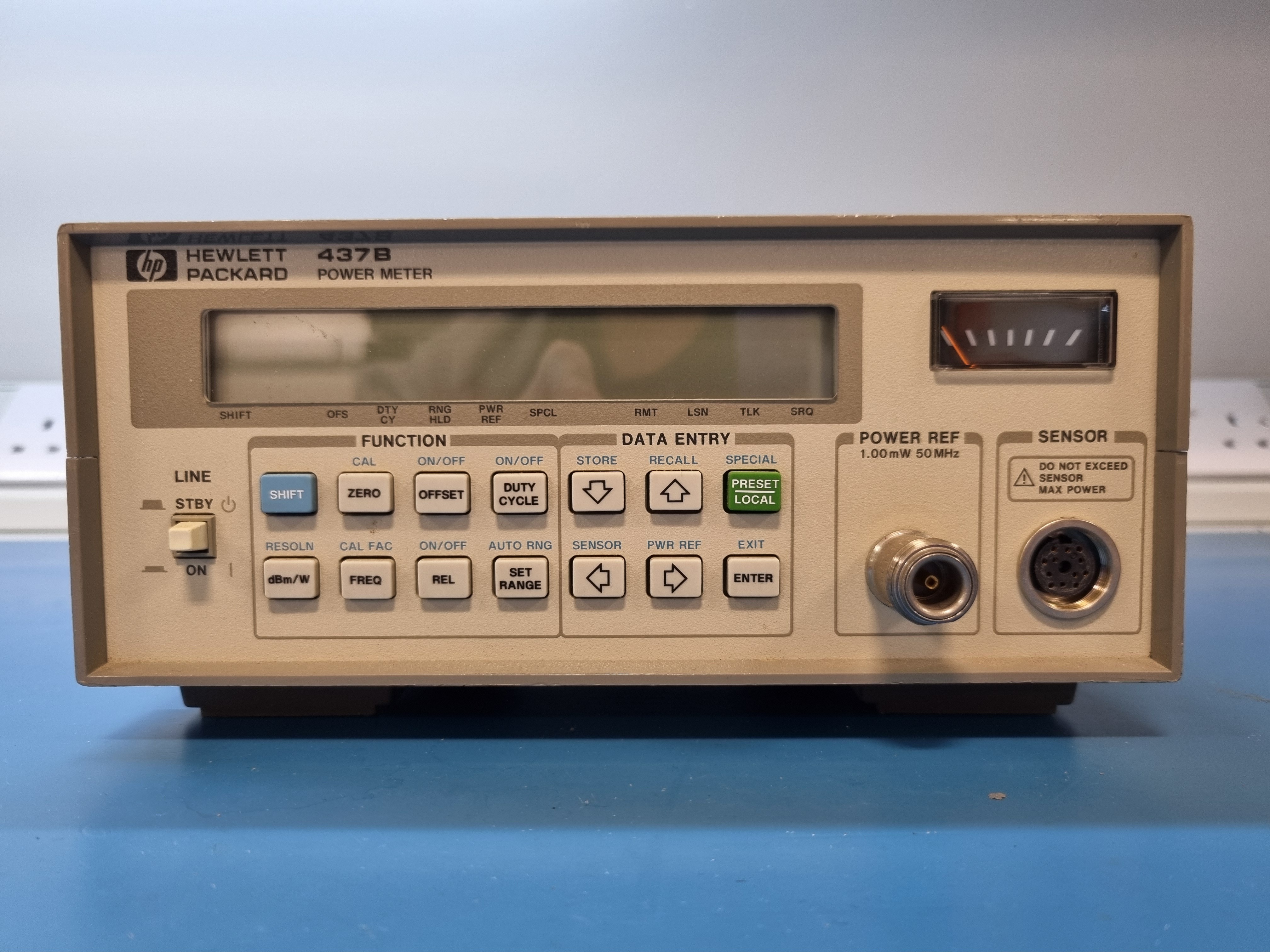
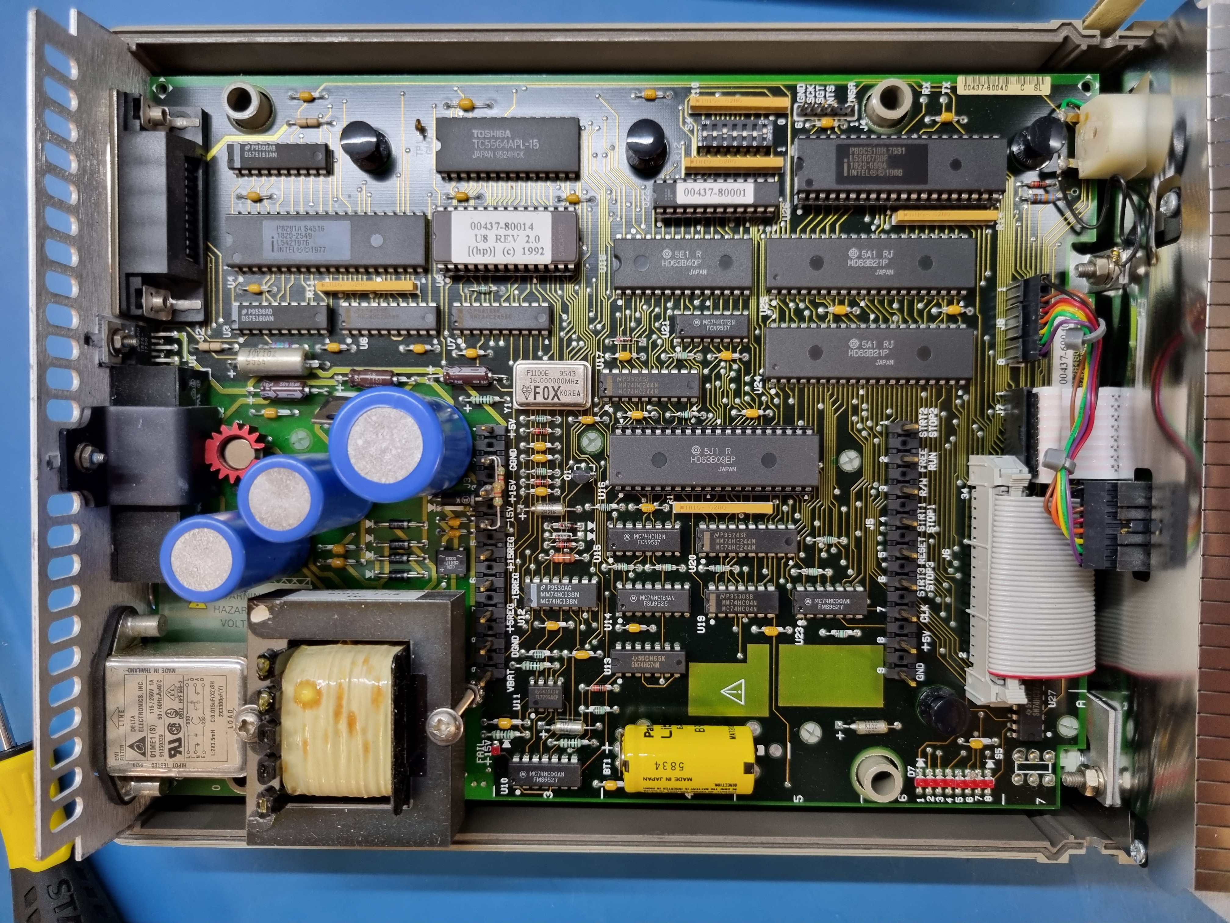
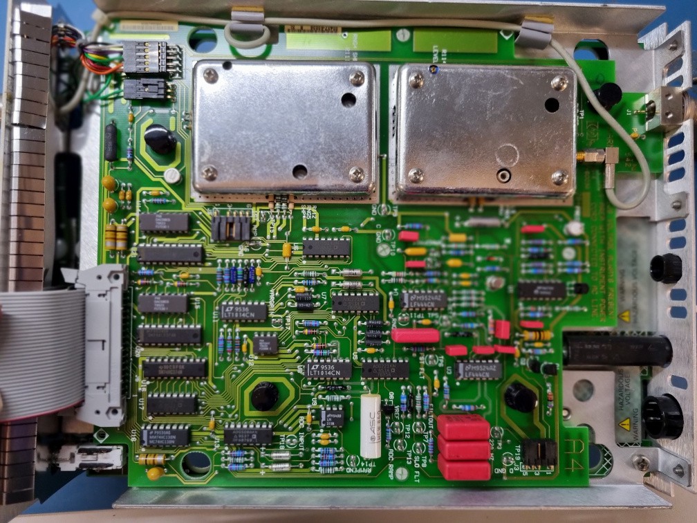
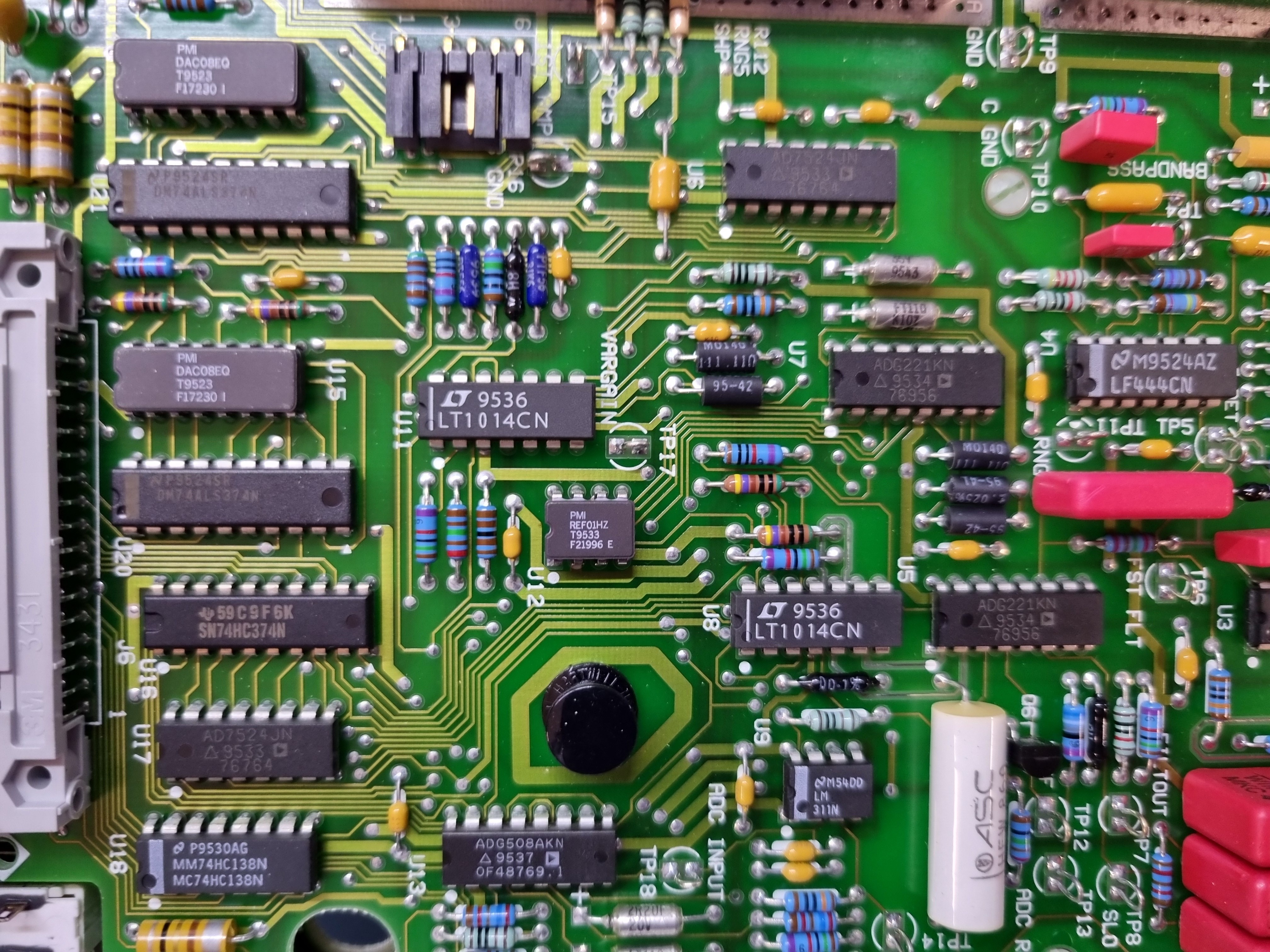
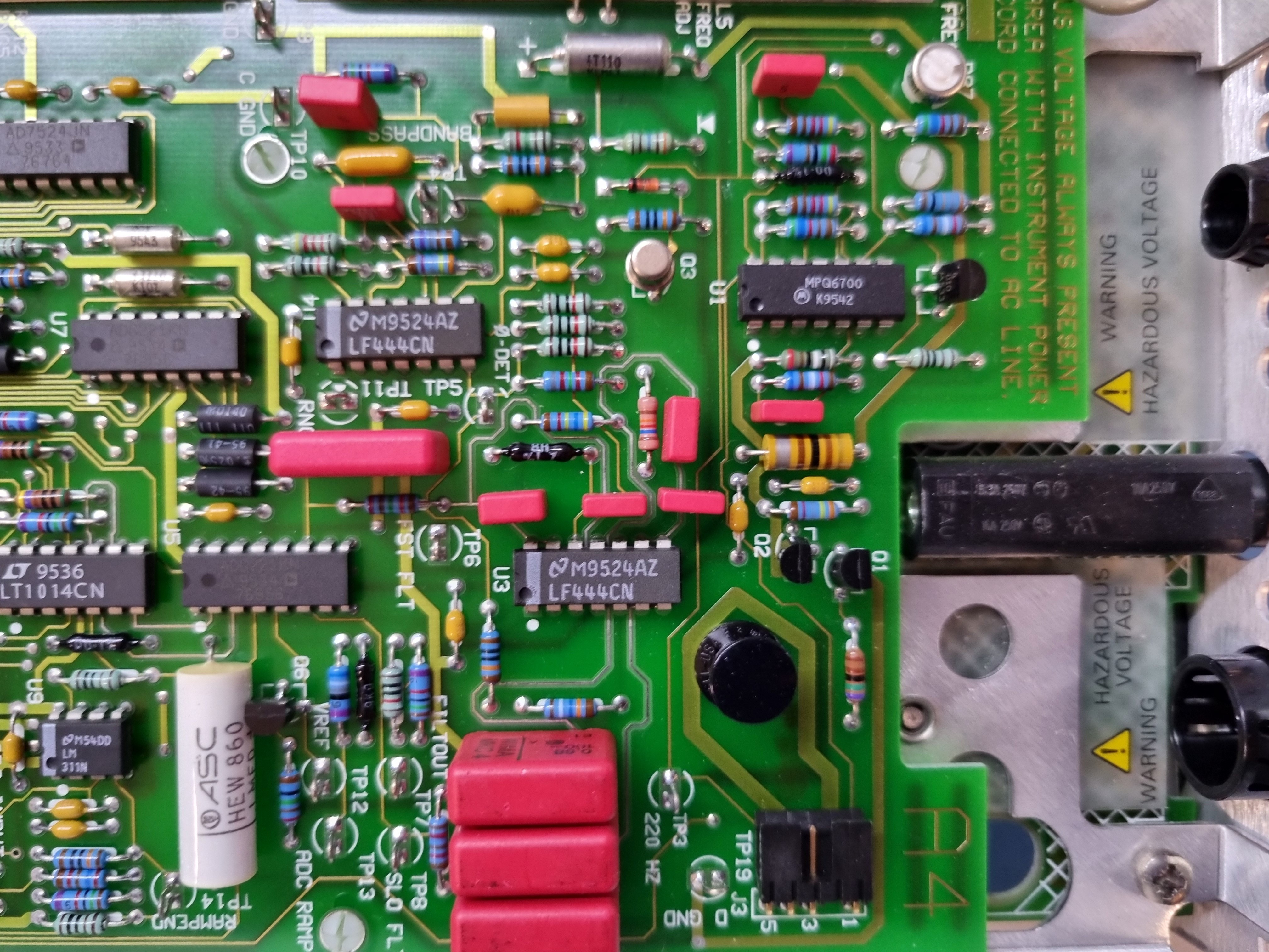
Close
0%
0%

HP437B power meter teardown

HP437B power meter examination

Similar projects worth following
Item was tagged "faulty" (without saying what the fault was. I had a look inside.
It wakes up, does a self-test, without complaint.

An instrument built with 1980s era parts, all through hole, no SMDs, or ASICs. You can look at what is inside and see the hardware structure and what is going on.

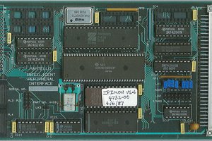
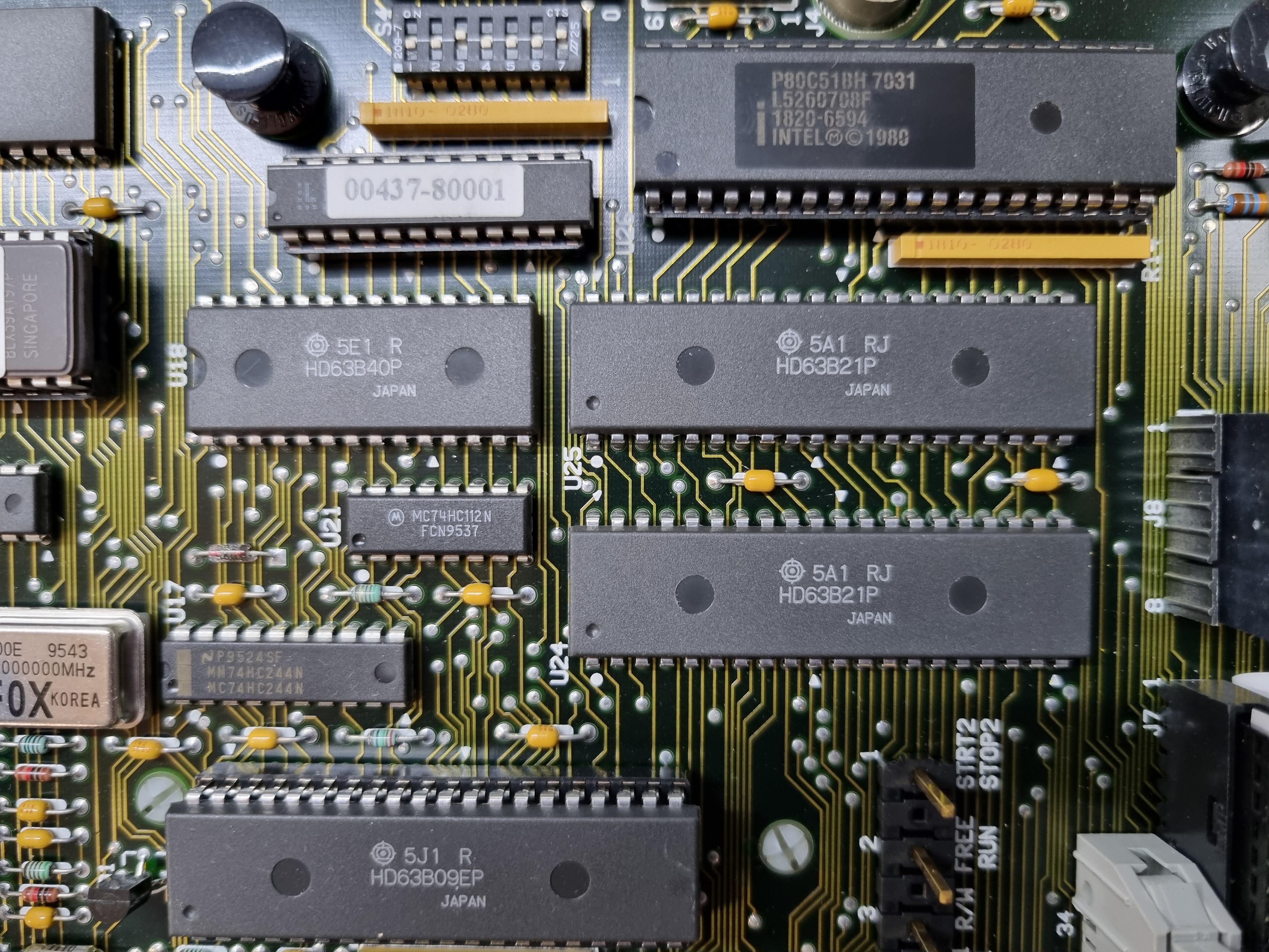
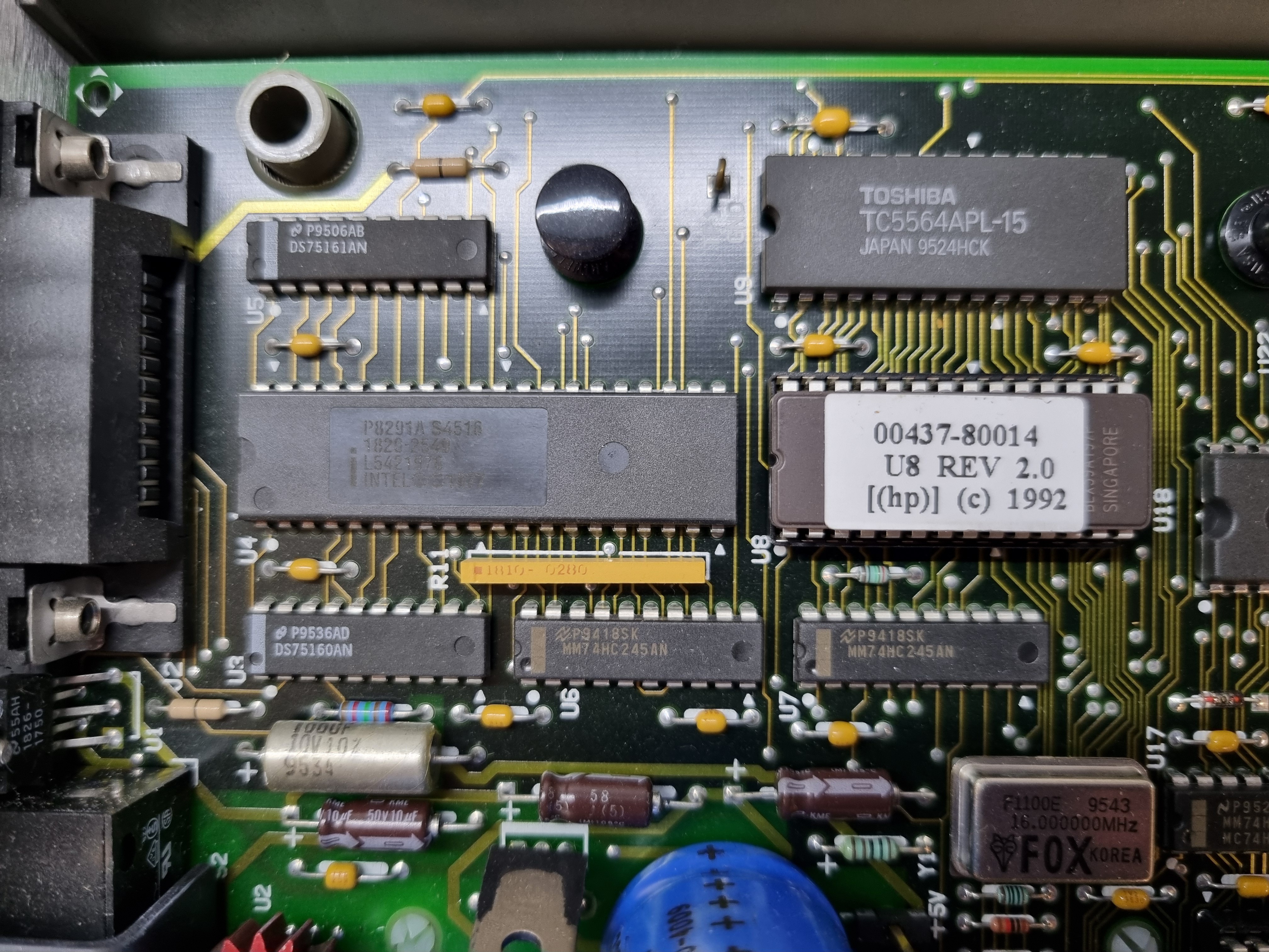
Controlled by a 6809 processor with 32K ROM and 8K RAM, plus an 8051 microcontroller.

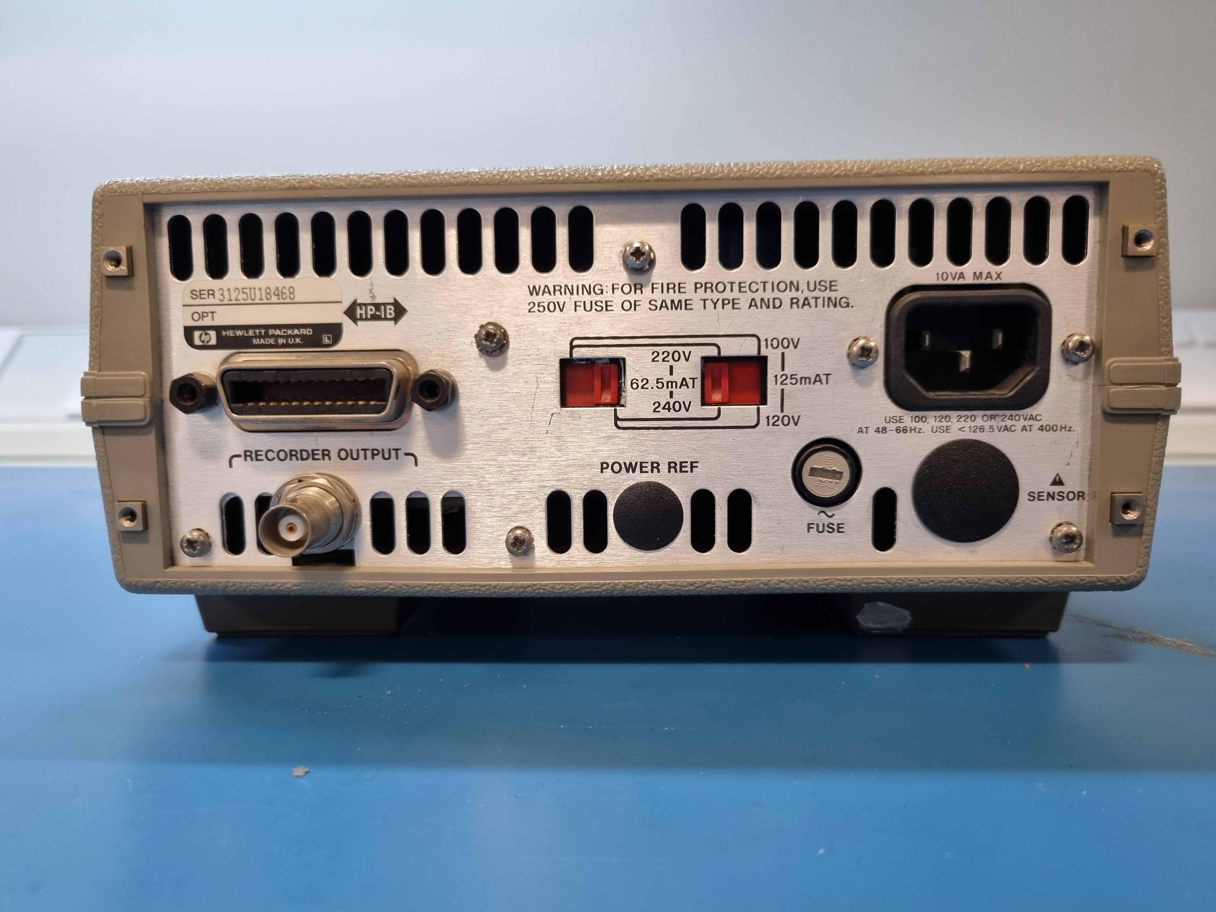
It has a 6840 programmable timer module but no serial I/O, just an IEEE488 peripheral interface.

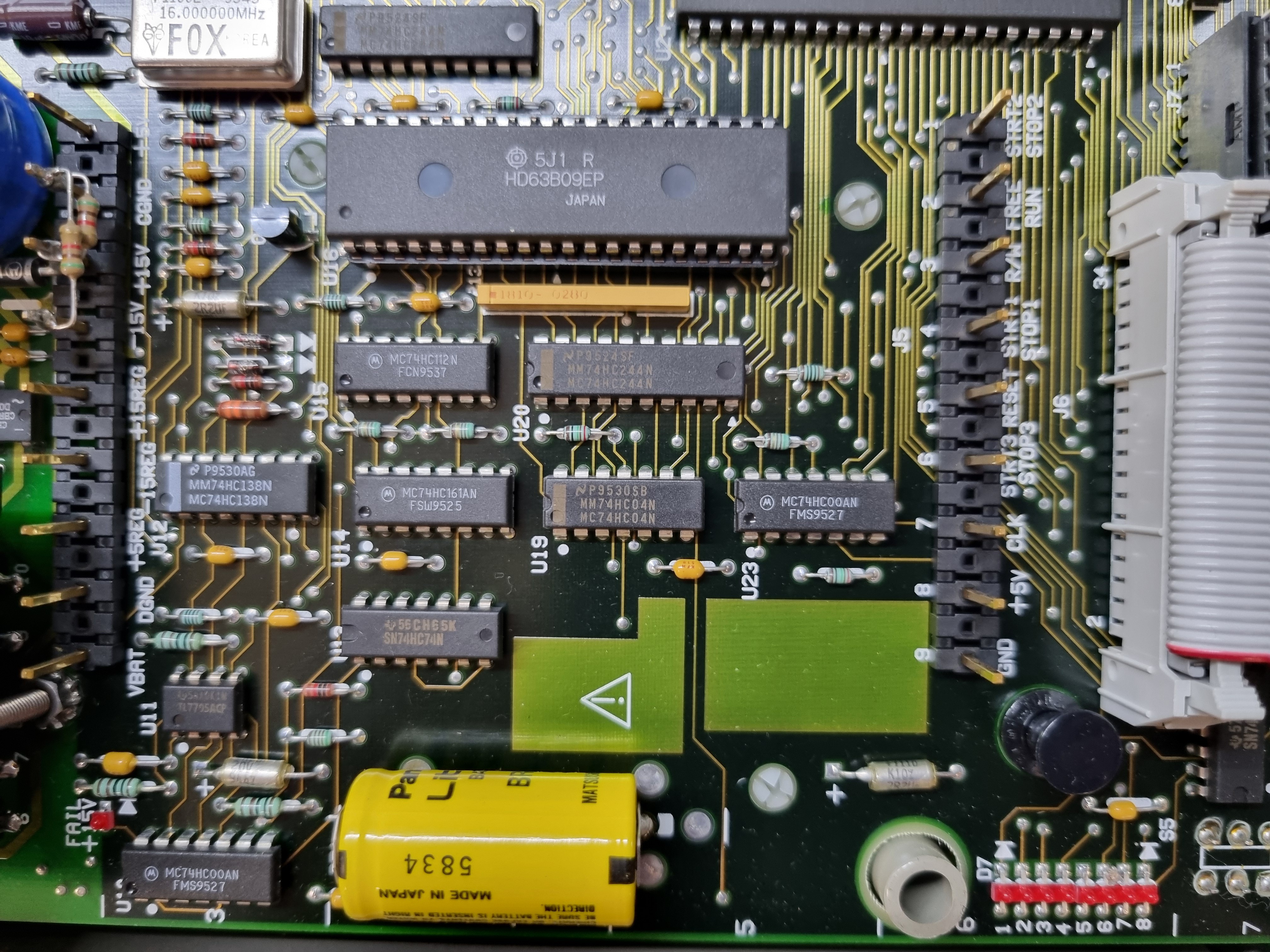
There is one GAL chip, without the security bits blown.

I have read the GAL and the firmware ROM.

text/plain - 975.30 kB - 03/09/2024 at 03:03

Download

text/plain - 311.97 kB - 03/09/2024 at 03:02

Download

U8rev2-0.info.txt

information guiding the disassembler

plain - 9.53 kB - 03/09/2024 at 19:31

Download

application/x-shellscript - 367.00 bytes - 03/08/2024 at 01:40

Download

plain - 2.03 kB - 02/28/2024 at 00:20

Download

View all 15 files

  • ROM disassembling

    Keith03/08/2024 at 01:37 0 comments

    I installed this disassembler:

    https://github.com/Arakula/f9dasm

    and had a first go at disassembling.

    It is a pretty powerful tool.

    Much of the ROM seems to be arrays of words, making me wonder if there if they used some kind of FORTH interpreter to get the code density up. 

    I don't have time to reverse engineer FORTH code!

  • Photos

    Keith02/23/2024 at 02:12 0 comments

    Front view:

    Rear view:

    Bottom view, feet;

    Two screws were hidden under the round calibration labels.

    Bottom view, two rear screws hidden under the feet:

    Side view, pull the sticky bits off:

    Complete top board:

    Ooh look, a 68B09E. The 63B40 is a programmable timer module serial I/O and the two 63B21 provide parallel I/O.

    I don't know what the 80C51 microcontroller does. Maybe helps manage the front panel?

    The oscillator is 16 MHz.

    ROM (8k), RAM (8k HN27C64) and the IEEE interface:

    The intel P8291A is the IEEE488 talker/listener interface, the DS75160AN and DS75161AN are the buffers in standard 0.3" wide DIP (unlike the Texas Instruments buffers).

    I don't know what the logic chips below the CPU do.

    The battery is a very healthy 3.45 volts.

    Underneath is the analogue board. The two metal cans shield the RF stuff.

    Close-up views

View all 2 project logs

Enjoy this project?

Share

Discussions

Similar Projects

Does this project spark your interest?

Become a member to follow this project and never miss any updates