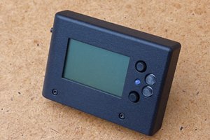
Close
0%
0%

TTi 1705 True RMS multimeter teardown

A digital multimeter from the age of through-hole off-the-shelf components

Similar projects worth following
A look at what went into a DMM before it all went into ASIC chips. It is cheaper to buy a modern meter with a rotary switch that mimics the early analogue meters, so this is beyond economic repair. But exploring this gadget is more interesting, and possibly educational as well.
No longer made, superseded by a newer version.

On starting up, the display value flashed continuously. I guessed that it does that to indicate 'overload' on the resistance range, and this is indeed the case. It showed steady and accurate readings when measuring a resistor.

Voltage measurements agree with a handheld meter.

Frequency range shows 50 Hz mains hum when nothing connected, and 0 Hz when probes are shorted together.

Adobe Portable Document Format - 1.01 MB - 03/10/2024 at 01:04

Preview
Download

TTi_1705_Operating_Instructions_EN.pdf

Includes the command set.

Adobe Portable Document Format - 889.47 kB - 03/10/2024 at 00:45

Preview
Download

Adobe Portable Document Format - 401.40 kB - 03/10/2024 at 00:45

Preview
Download

MAX132.pdf

±18-Bit ADC with Serial Interface. No Longer Manufactured.

Adobe Portable Document Format - 129.27 kB - 03/06/2024 at 11:35

Preview
Download

JPEG Image - 3.05 MB - 02/29/2024 at 22:20

Preview
Download

View all 9 files

  • Command set

    Keith03/10/2024 at 02:46 0 comments

    The serial port command set is not the same as the GPIB command set.

    Automated Test Equipment will have to parse ASCII command/response strings to extract the data.

  • Serial port

    Keith03/10/2024 at 02:31 0 comments

    The serial port pin-out is cunning designed so that you can connect to a PC with a simple modem cable, or daisy-chained with other TTi devices.

    1 Power to optional PC-02
    2 TXD Transmitted data from instrument to PC
    3 RXD Received data to instrument from PC

    4 nc 5 GND Signal ground 6 nc 7 RXD2 Secondary received data 8 TXD2 Secondary transmitted data 9 GND Signal ground

    Note that the pins 2, 3 and 5 match the IBM PC DE-9 connector standard.

    Pins 7, 8 and 9 connect to the next device in the chain. They replace the RTS, CTS and RI functions. The signal directions are the same, avoiding buffer damage if the device is connected to the PC port pins.

    It is a clever way of implementing a GPIB-style chain on RS232, but both GPIB and RS232 have largely been replaced by USB, or Ethernet.

View all 2 project logs

Enjoy this project?

Share

Discussions

Similar Projects

Does this project spark your interest?

Become a member to follow this project and never miss any updates