 Kuldeep Singh Dhaka
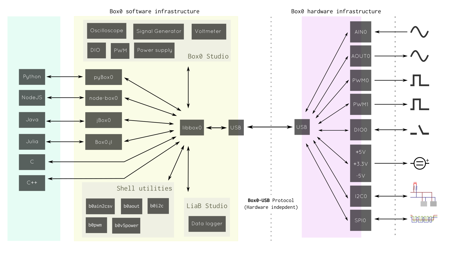
The problem
The current model of scientific and technical education focuses more on preparing students to copy classroom notes and undergo theoretical exams rather than actually doing science and learning about the process in a manner similar to practicing scientist or engineer.
The laboratory is seen as a less important component and the list of so called standard experiments have documented outcomes and use ready made setup for the sake of "convenience" and compensating for shortage of time that occurs due to exam preparation.
This negatively affects the shaping of students as scientific thinkers, takes out the joy of learning from science education and creates a negative perception of the field being rather dry and boring.
we decided to solve the problem by designing a personalized and affordable educational platform for aspiring scientists and engineers that supports independent learning, freedom to learn anytime anywhere and enables multidisciplinary and open ended explorations.
Box0
Started with the idea of providing learners educational resources and tools that gives the freedom to discover science, technology and electronics by doing and sharing knowledge with others.
As students, we wanted to have something that is affordable and help us learn not only in classrooms and restricted labs but anytime anywhere and can be used with a variety of open coursewares.
Box0 helps you learn about electronics and computers and how these are useful for studying physical, biological, chemical or some other phenomena.
Learn by doing
Learning should be active, playful and enjoyable.
With Box0 you can create, learn concepts by doing experiments and make interesting projects.
Your lab in a Bag
Box0 give you the Freedom to learn anytime anywhere.
Learning can happen anywhere, be it classroom, labs or park.
Let your creativity and curiosity come outside.
Not just a tool for electronics
Box0 is a tool for bridging the physical world with digital.
Its not limited to just electronics, you can equally learn physics, chemistry, biomedical.
You can use Box0 for citizen citizen science or for your DIY lab experiments, with MOOC and open source tutorials.
Beginner friendly
Box0 comes with multifunction, free and ready to use software GUI.
You can use setup experiments using software instruments in minutes.
We have included everything you need to start.
Box0 is Extendable
You can program Box0 for custom applications. For example you can build your own low cost instruments.
Box0 works out the box with Jupyter notebook which can be used to Interface, control, visualise easily.
Software
- Box0 Studio (Qt) - Common Instruments GUI
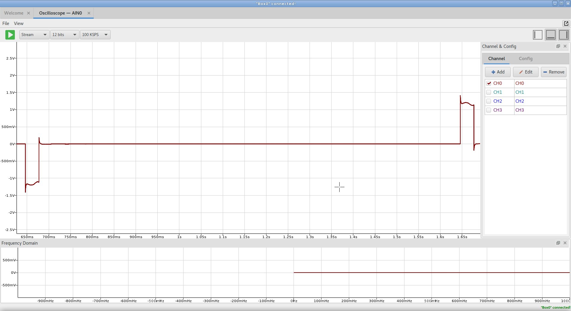
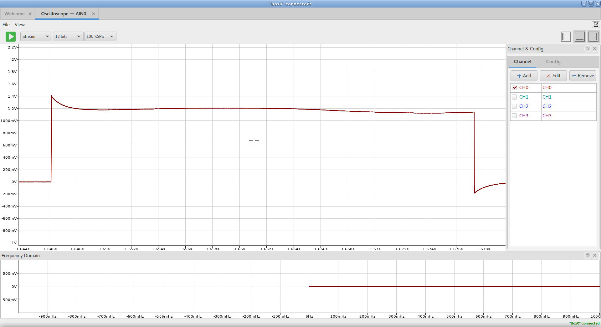
- Oscilloscope
- Function Generator
- PWM Generator
- Digital I/O
- Voltmeter
- Power Supply
- Box0 Studio (Android) - Box0 Studio for Android
- LiaB Studio (Qt) - Data Logging Software
- Capture and store in table
- Visualize Table Data
- Import/Export Data
- LiaB Studio (Android) - LiaB Studio for Android
- libbox0 - Communication library
- All Hardware communication via libusb
- Driver for Precision ADC, DAC
- pyBox0 - Python binding for libbox0
- Box0.jl - Julia binding for libbox0
- jBox0 - Java/Android binding for libbox0
- node-box0 - NodeJS binding for libbox0
- box0-utils - Shell utilities for Box0
- b0i2c - Interactive BusPirate like shell
- b0ain2csv - Capture and store signal to disk
- b0aout - Generate signal from shell
- b0v5power - control different power section
- b0pwm - Generate PWM signal
- libreplot - C Plotting library for GPU/OpenGL
Hardware
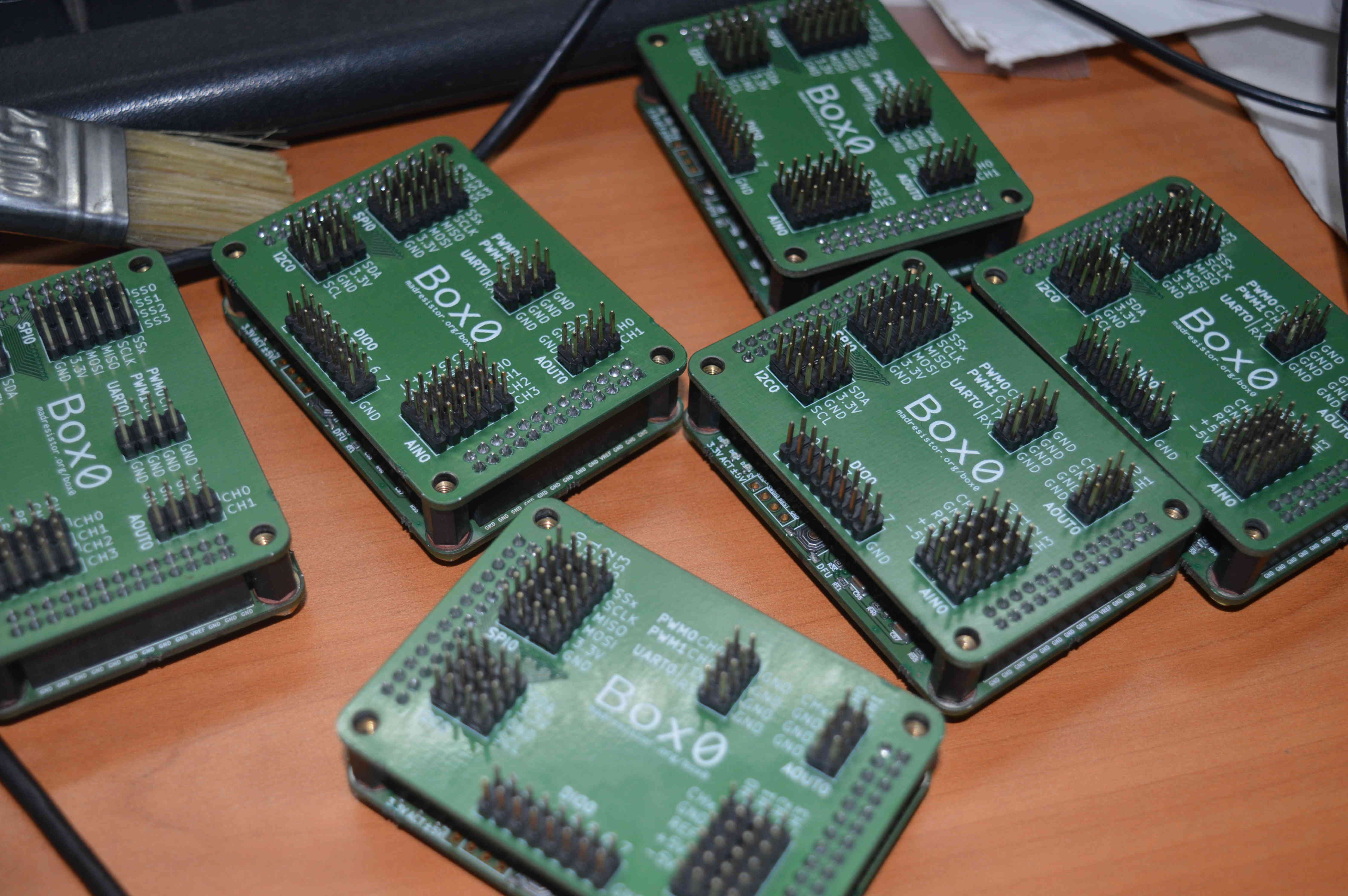
- Base (box0-v5) Board
- [box0-v5] Firmware
- Breakout Board - Quick prototyping
All source code, hardware design are released under a Free/Open Source software, hardware licence.
Logs
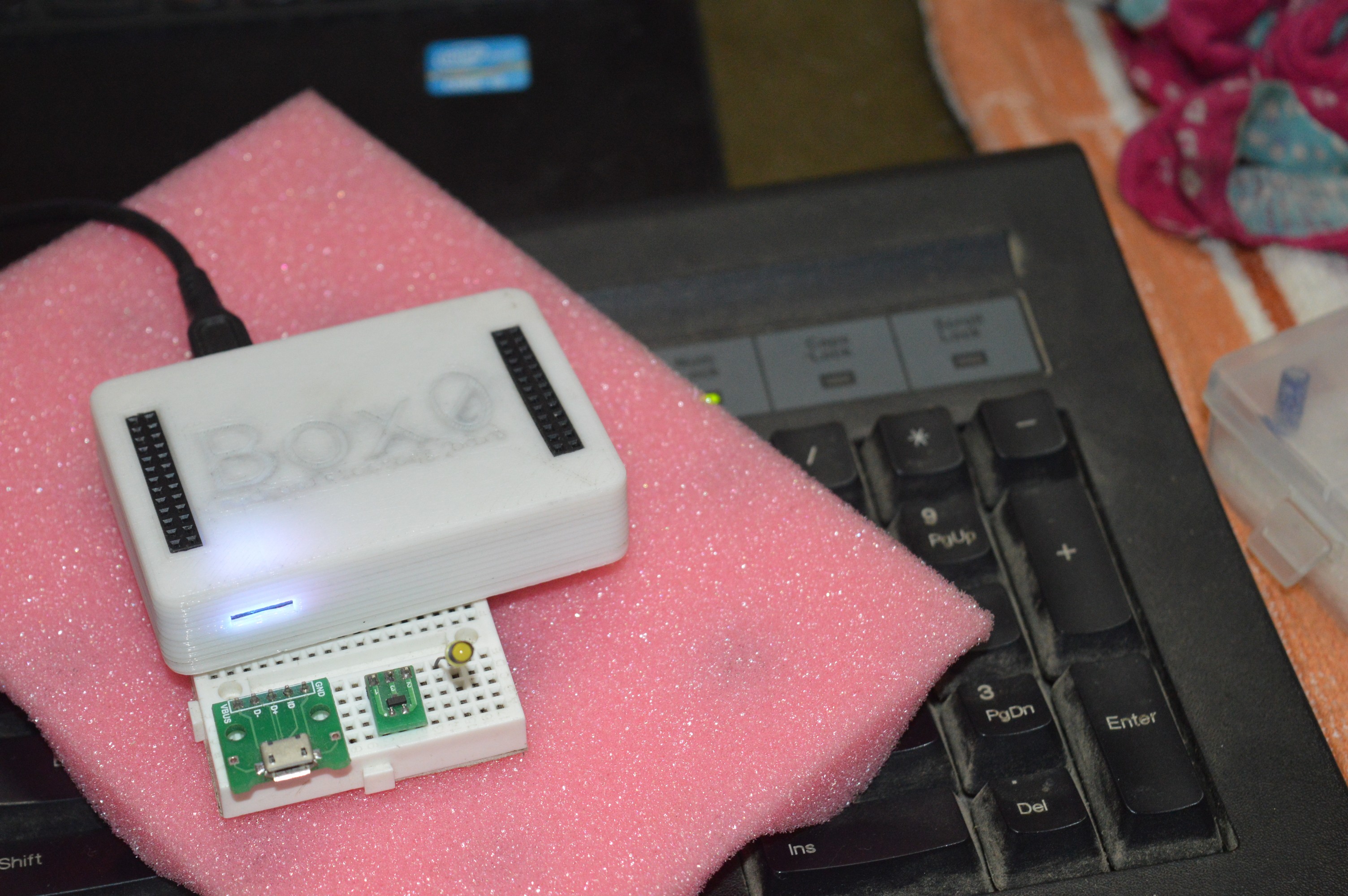
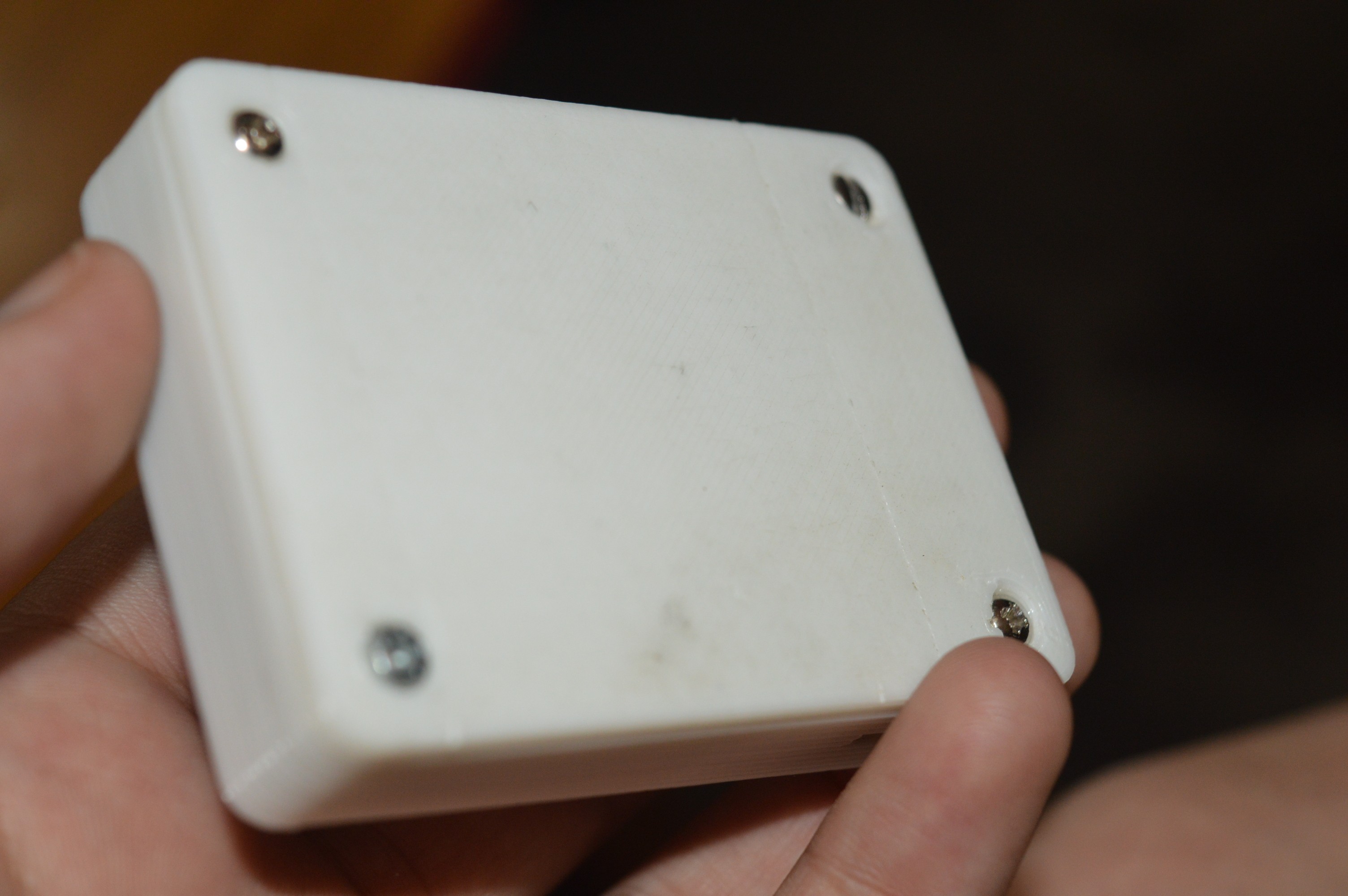
- 3D printed enclosure (prototype)
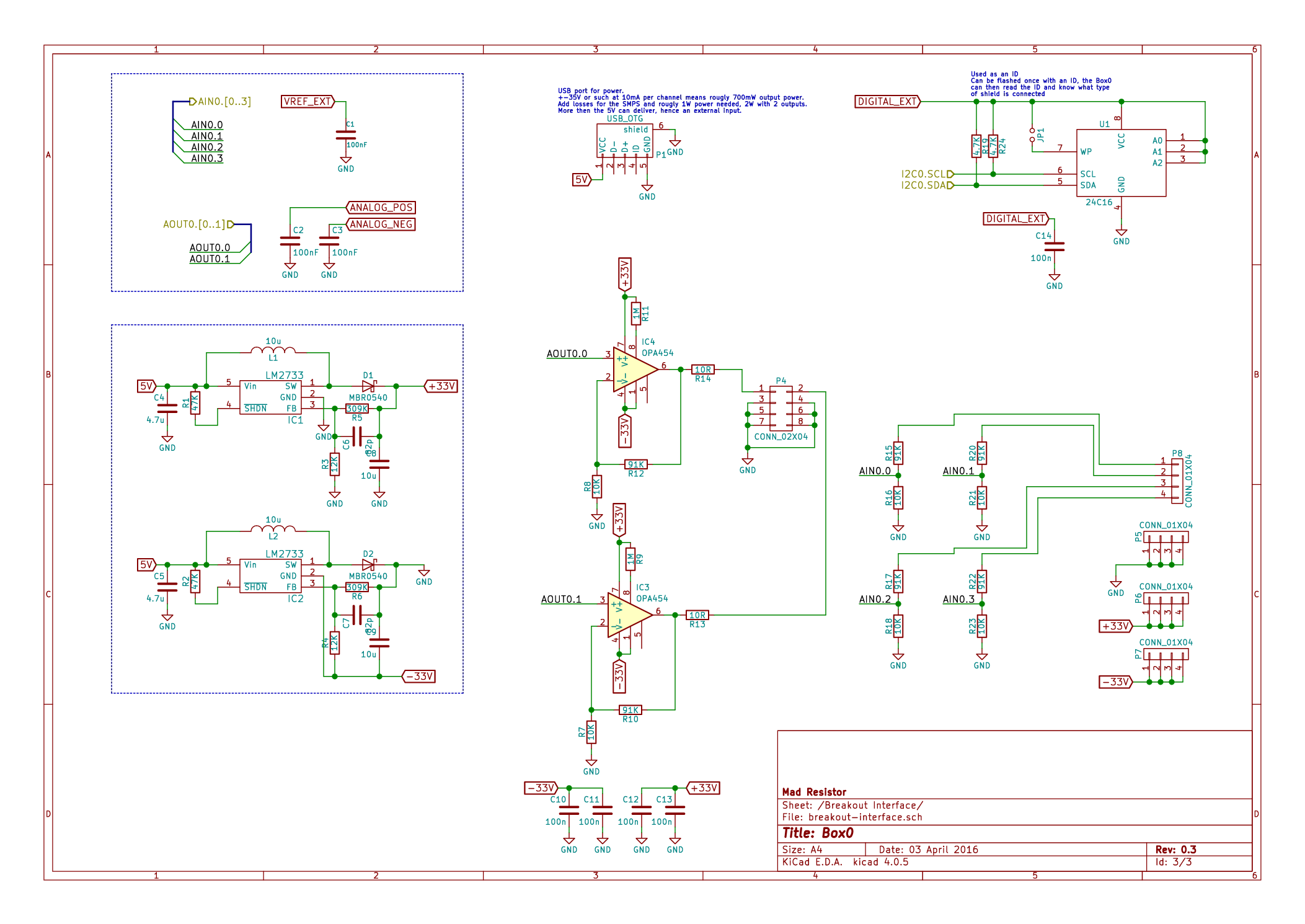
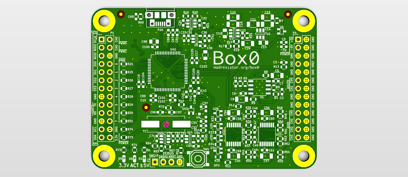
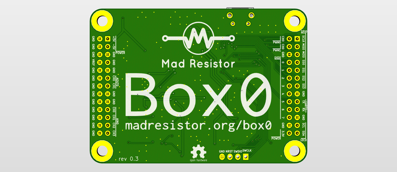
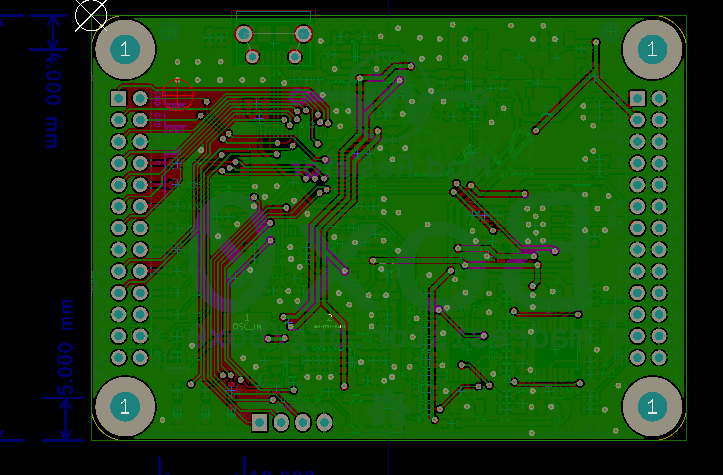
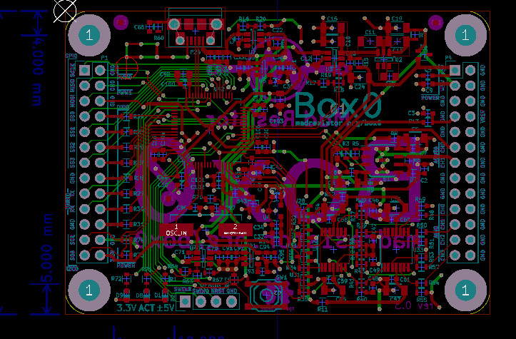
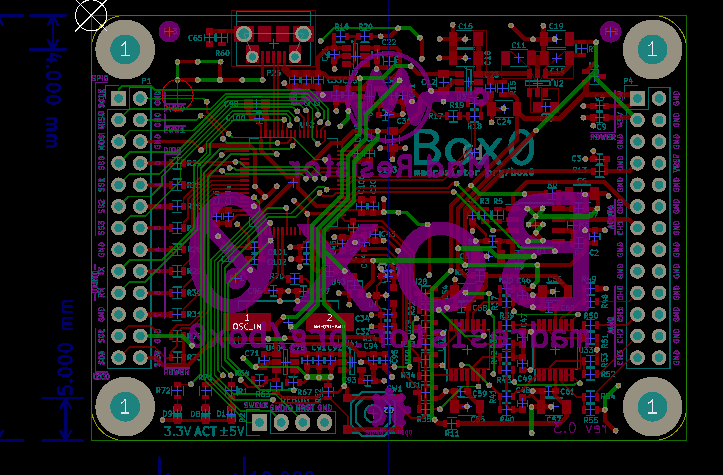
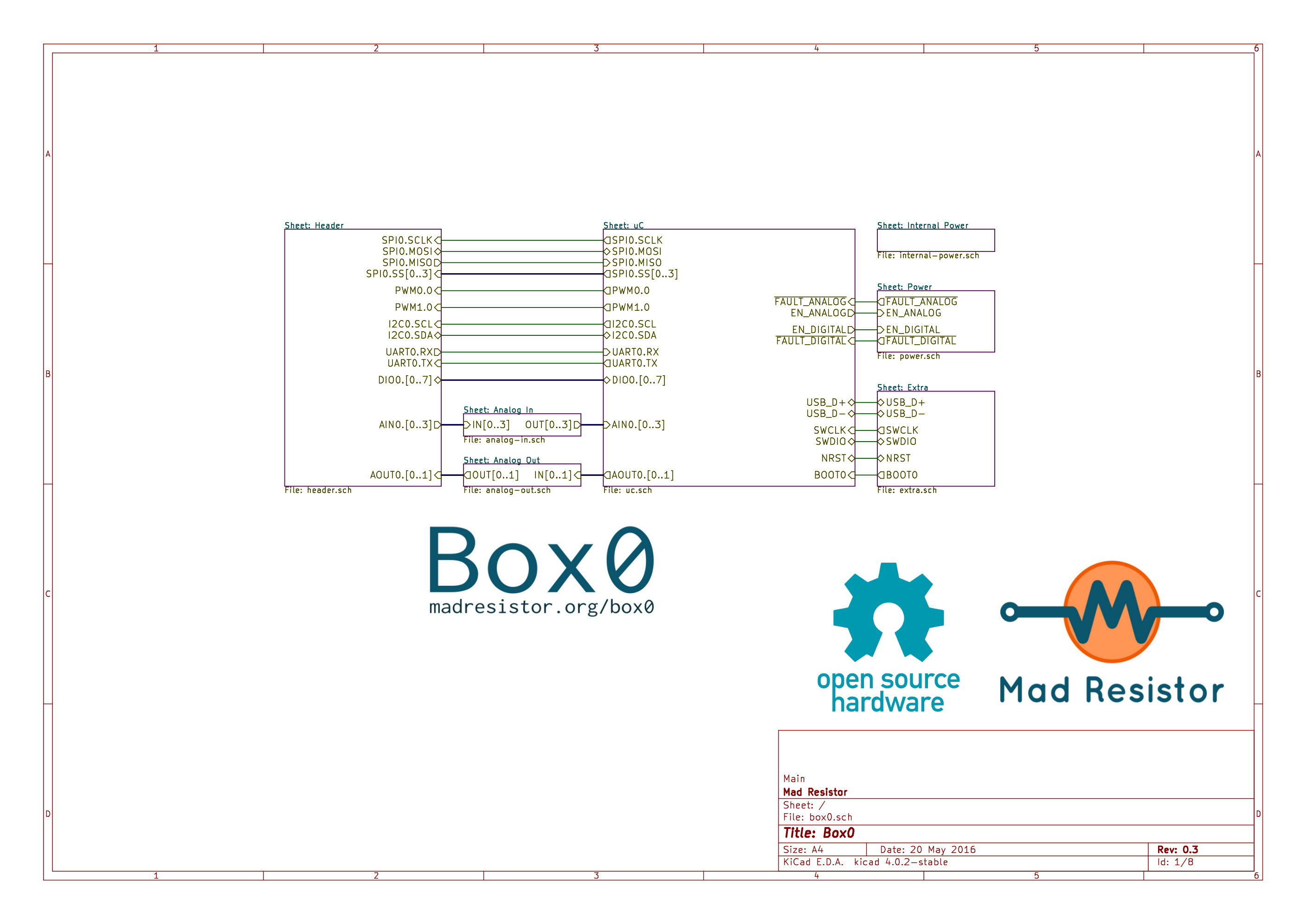
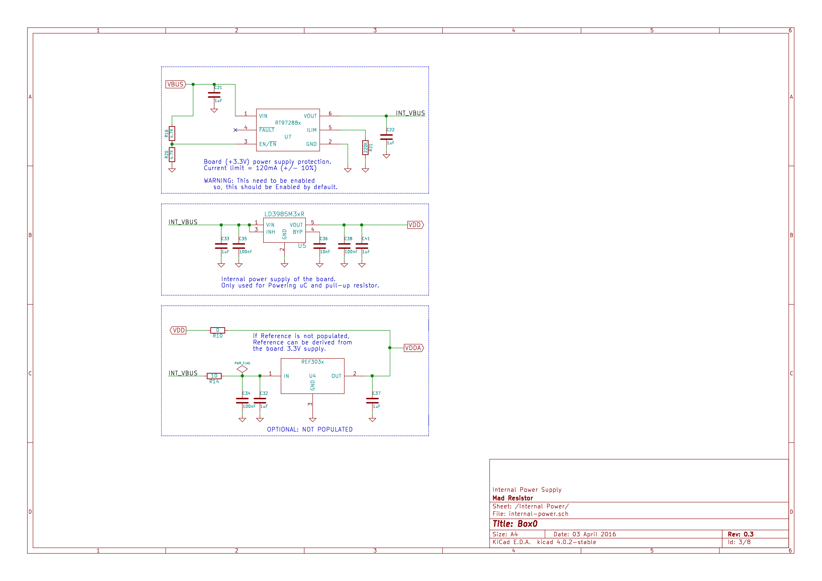
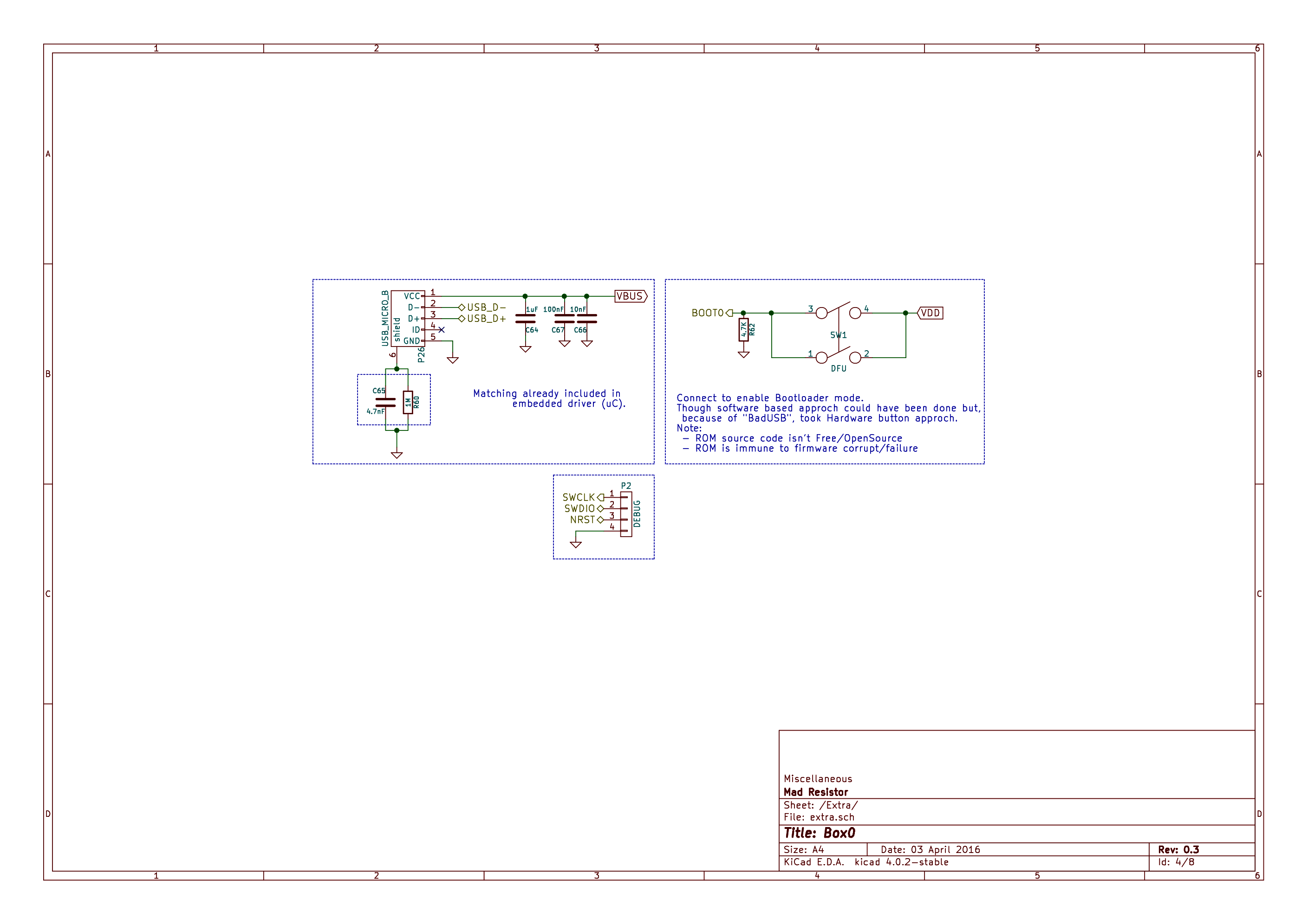
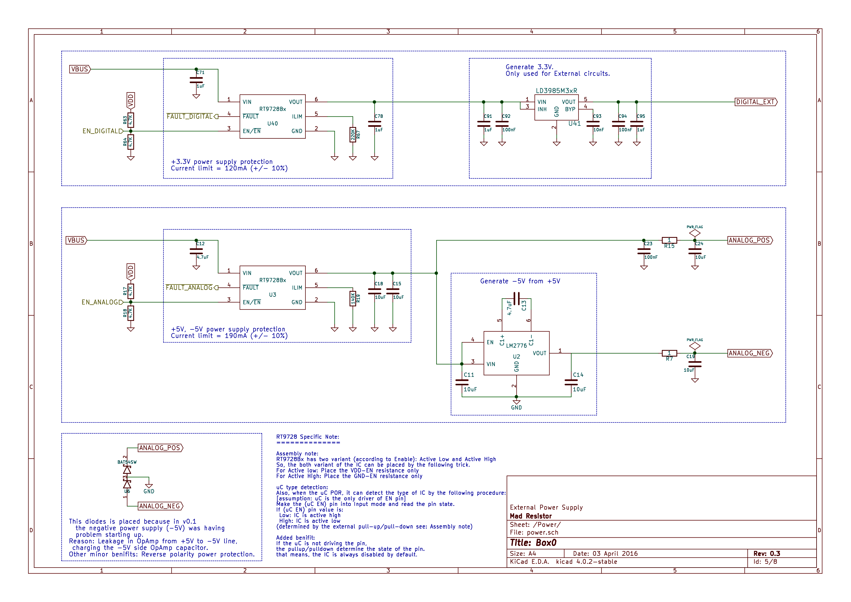
- Schematic documentation
- PCB (& 3D) ride!
- Building a Transistor curve tracer
- Red, Green & Blue Led I-V Characteristics
- Bode Plot of RC circuit
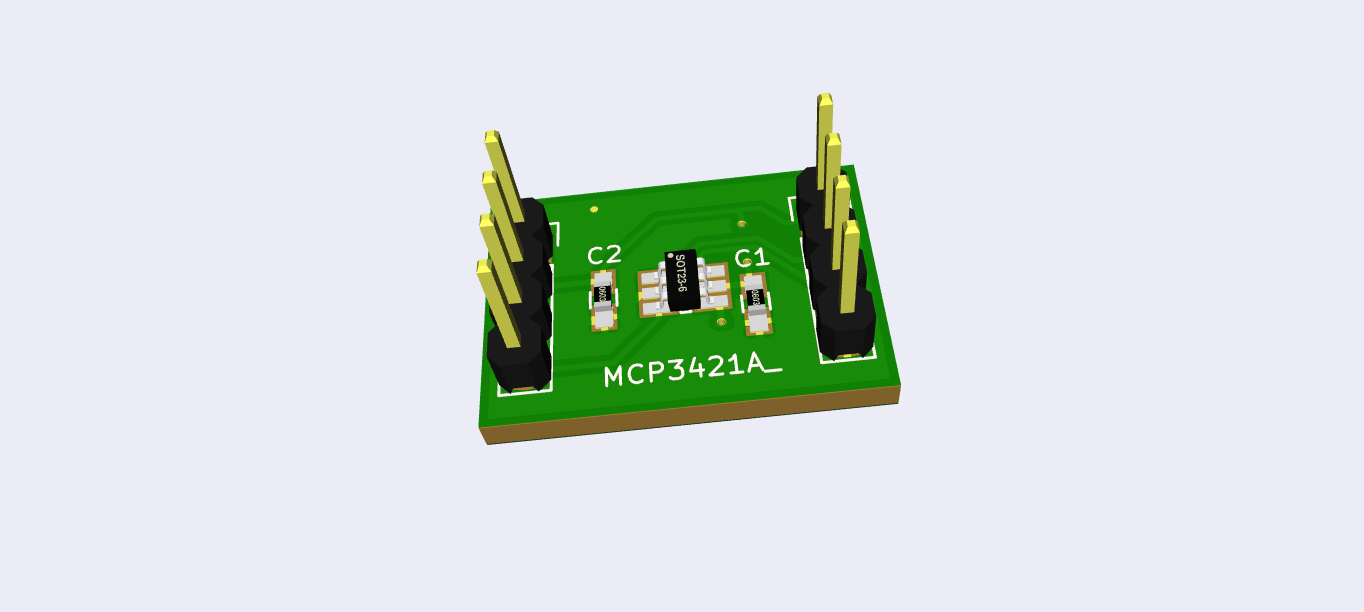
- Reading from MCP342x [16bit Sigma Delta] I2C ADC
- Box0 + Node.js = REST Server
- Box0 “Hello World”...

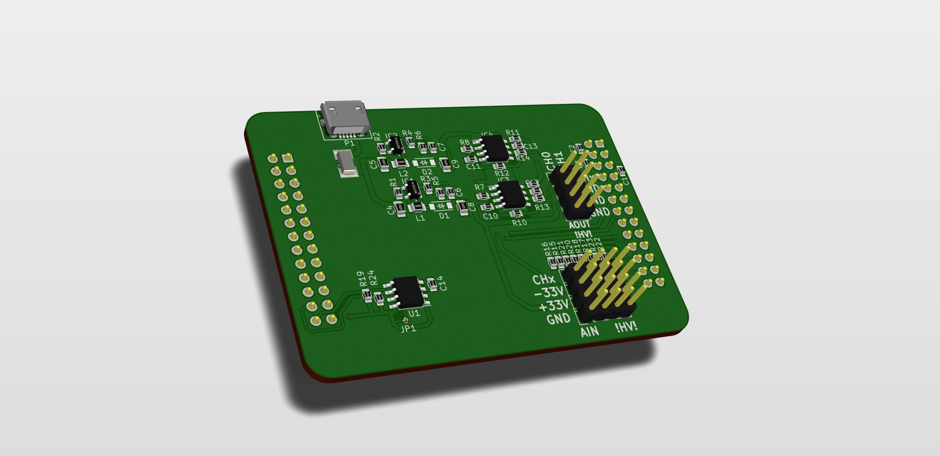
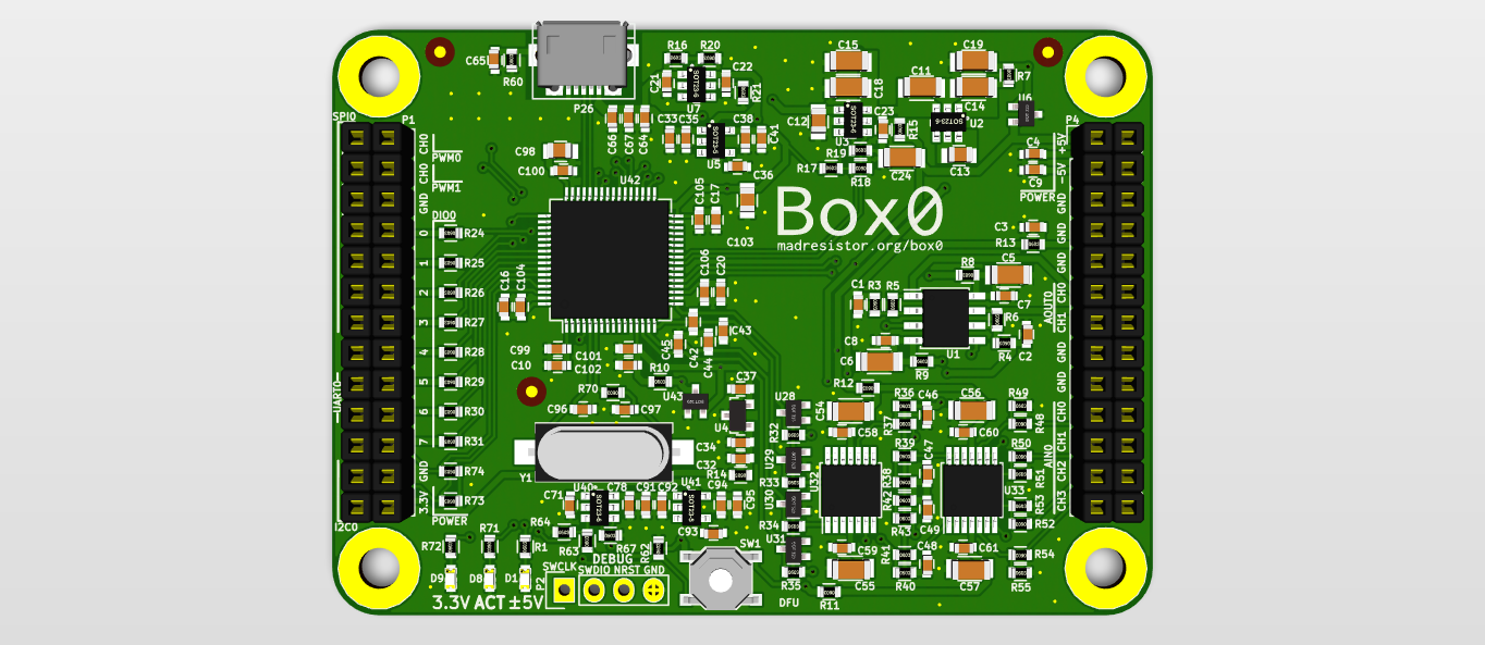
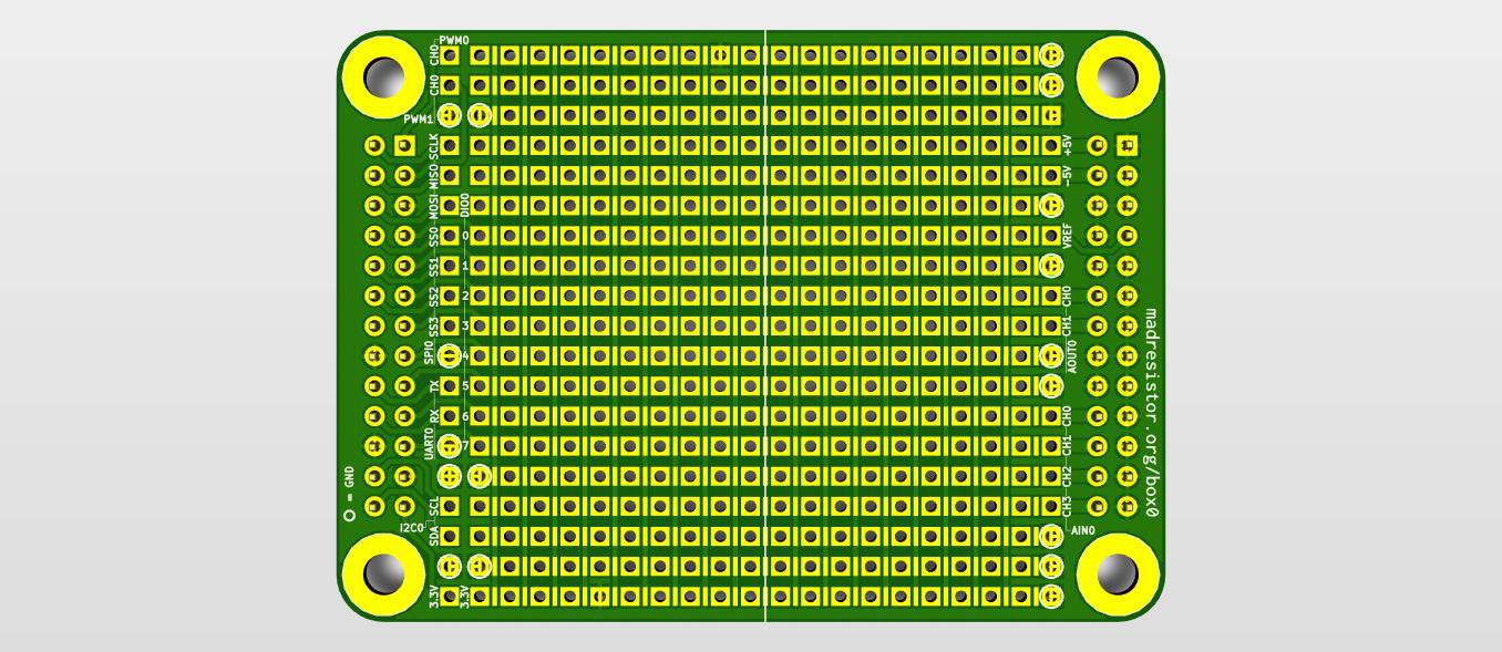
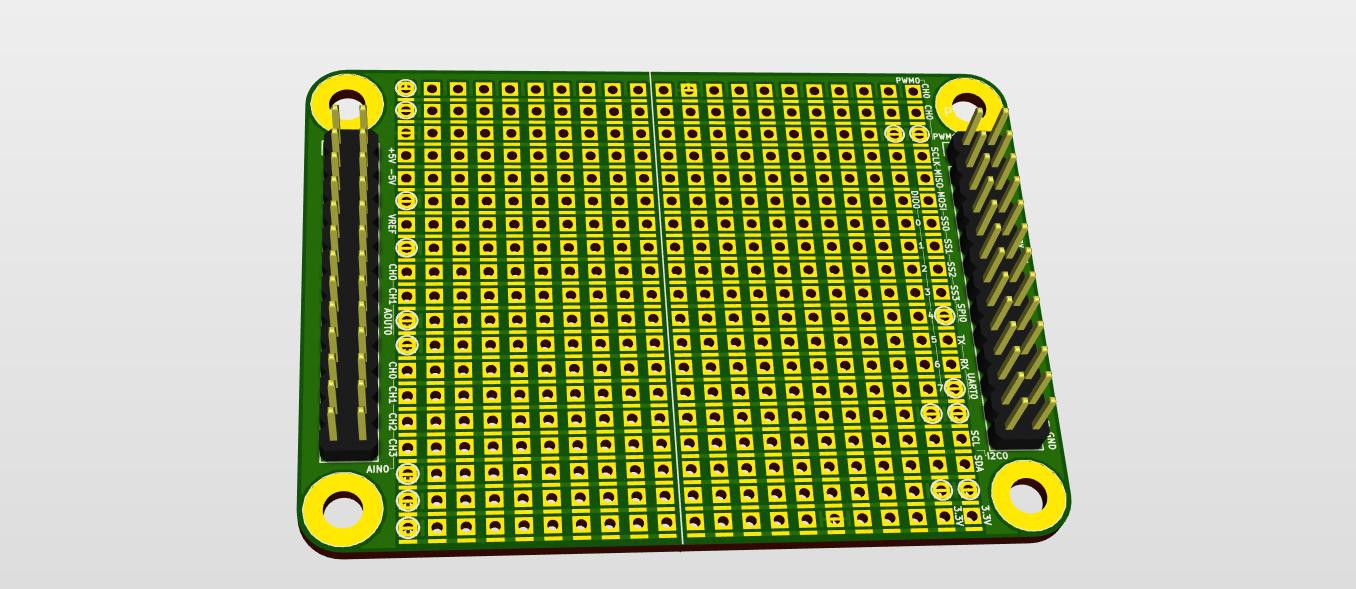
 3D Back - with components (computer generated)
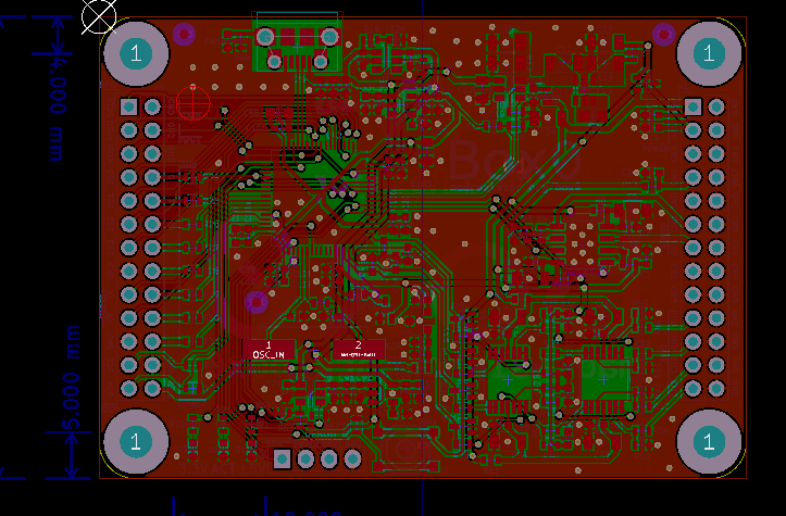
 Click on image for higher resolution.
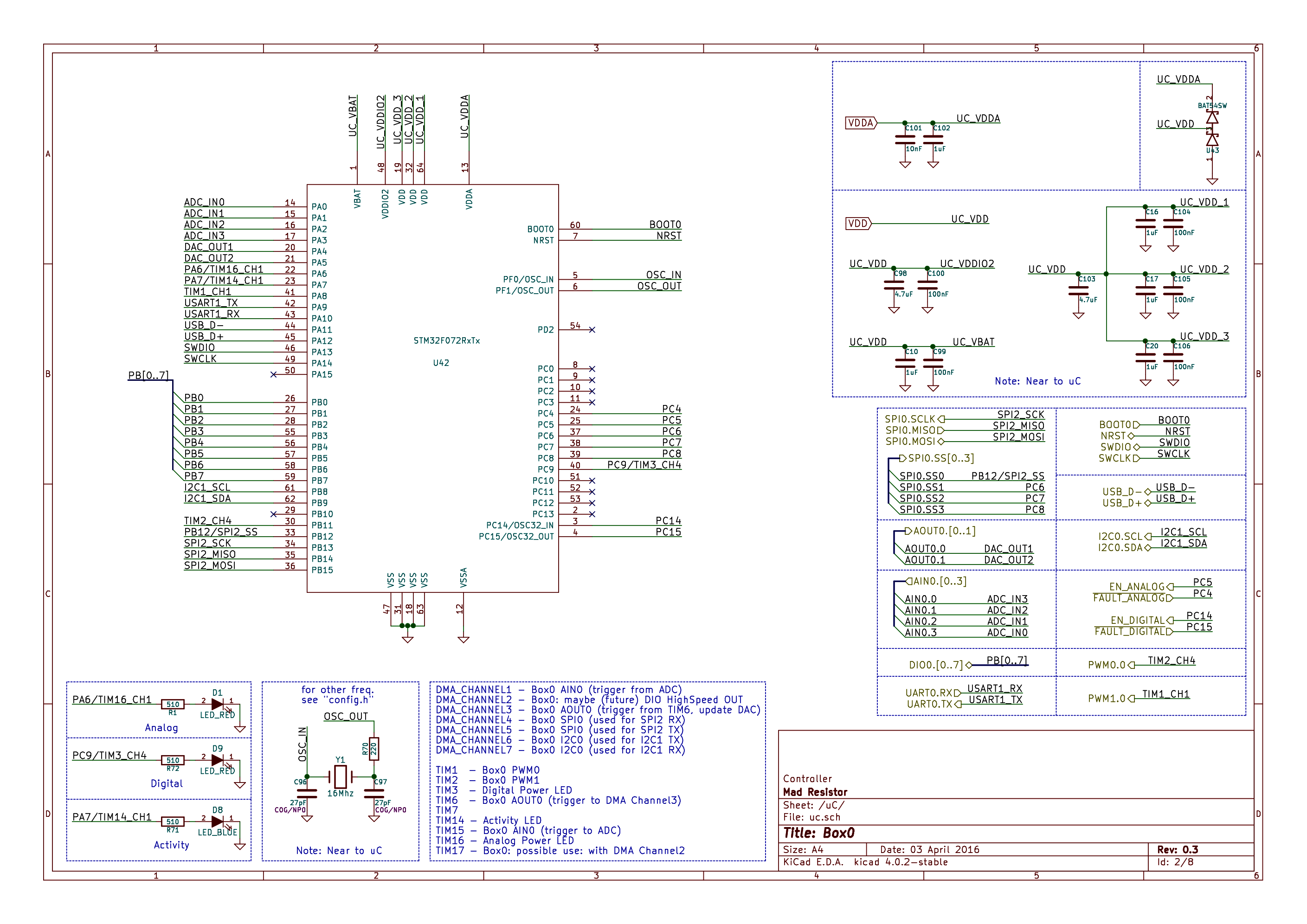


 Aleksa
 Scott
Scott
 John
John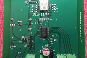
Hi Sandeep, are assembled box0s available to buy? I tried messaging you on the kitspace IRC but you seem to have fallen off that.