Close
0%
0%

Un-Inhibiting my Microcoin QL

Let me describe how I got my Microcoin QL coin acceptor to work.

Public Chat
Similar projects worth following
So I repair pinball machines & while most are set to "Free Play", it is nice to have a 'coin mech' in the coin door. Turn off Free Play for an 80's-arcade-throw-back! Yeah, it's silly to put your own quarter into your own pin, only to pull it out a few days later. Pure silliness but that's what pinball is about! Anyway the coin mechs are mechanical & tailored for a country's coin. I got a few for quarters, one for Loonies, another for Euros. The all mechanical design is amazing. I then stumbled on the modern'ish equivalent incorporating electronics, the ability to program & accept multiple types of coins, with fraud prevention measures, & a whole host of other capabilities to address the needs of a greater industry in vending & Gaming (gambling.) Toto, I've a feeling we're not in Kanas anymore. When I began, I was unaware of my folly. I simply proceeded to a big on-line auction site & purchased a Microcoin

Bottom Line Up Front

This has all been done before and those involved with vending and Gaming will no doubt already know everything here. This is the shortest explanation I can provide that excludes all detail.

TL;DR

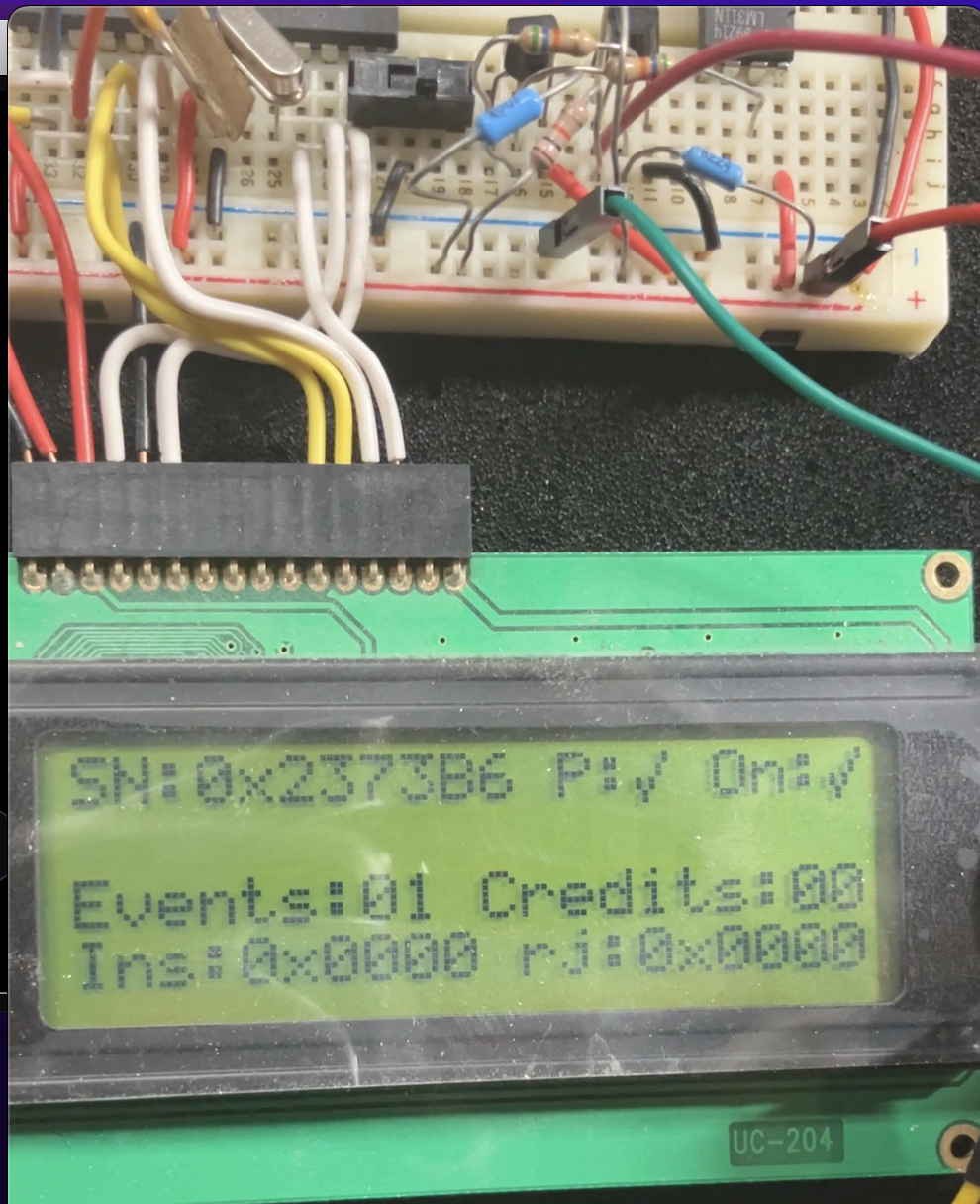
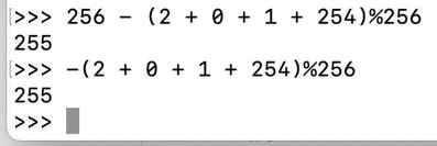
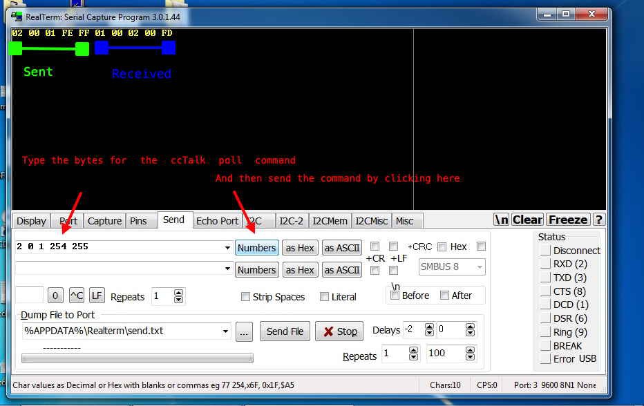
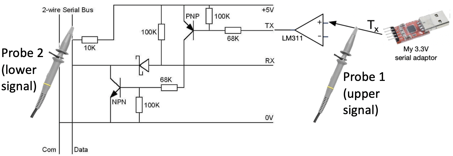
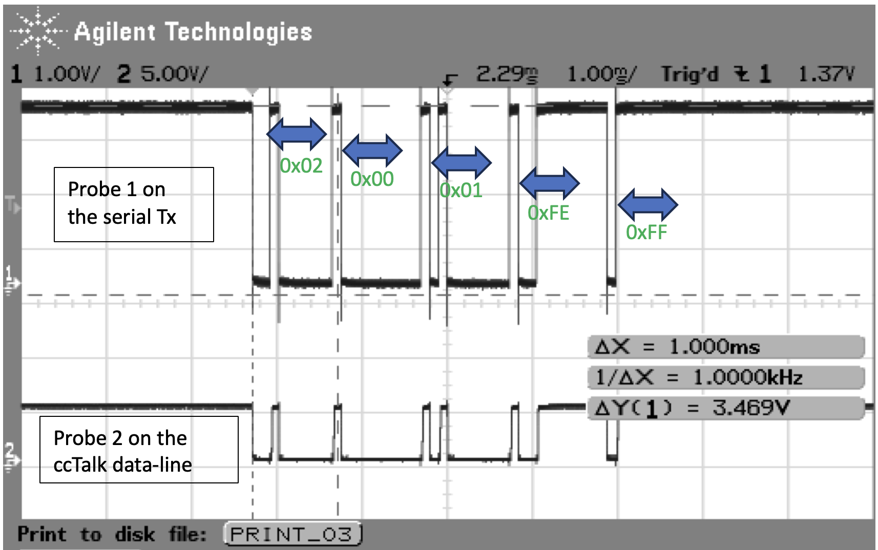
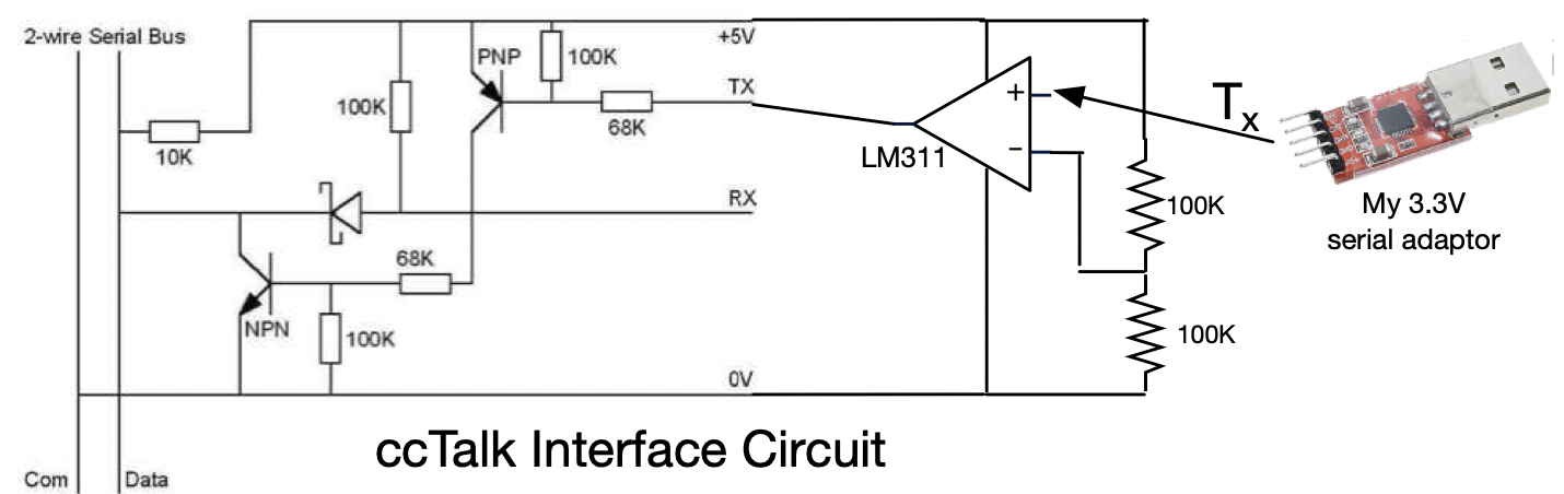
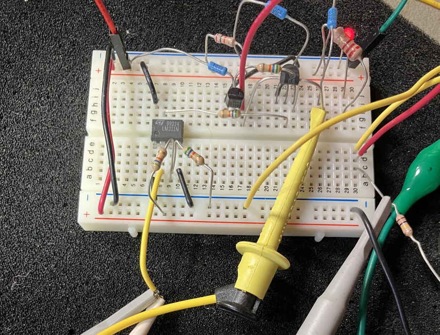
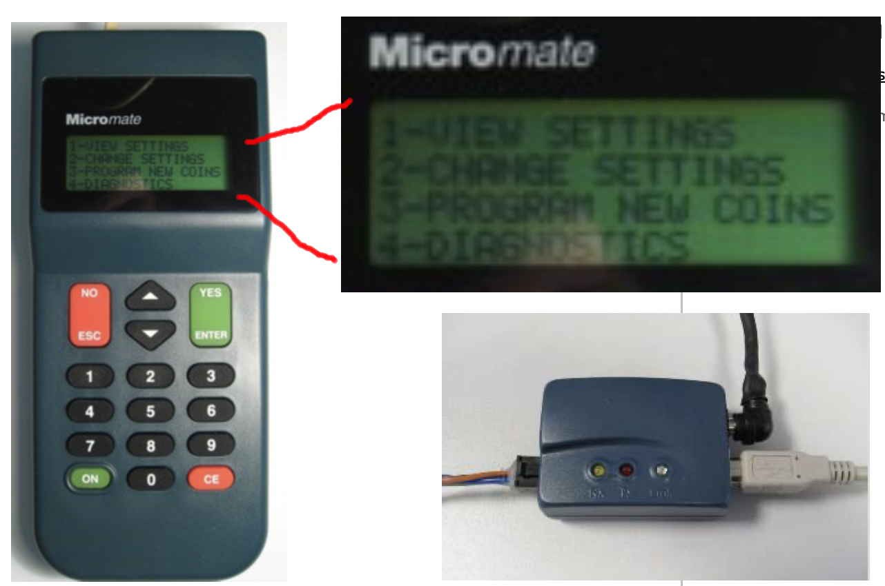
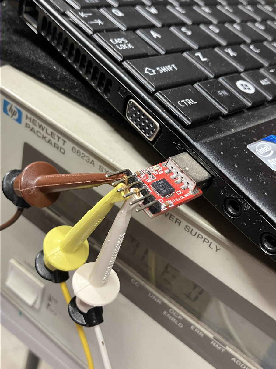
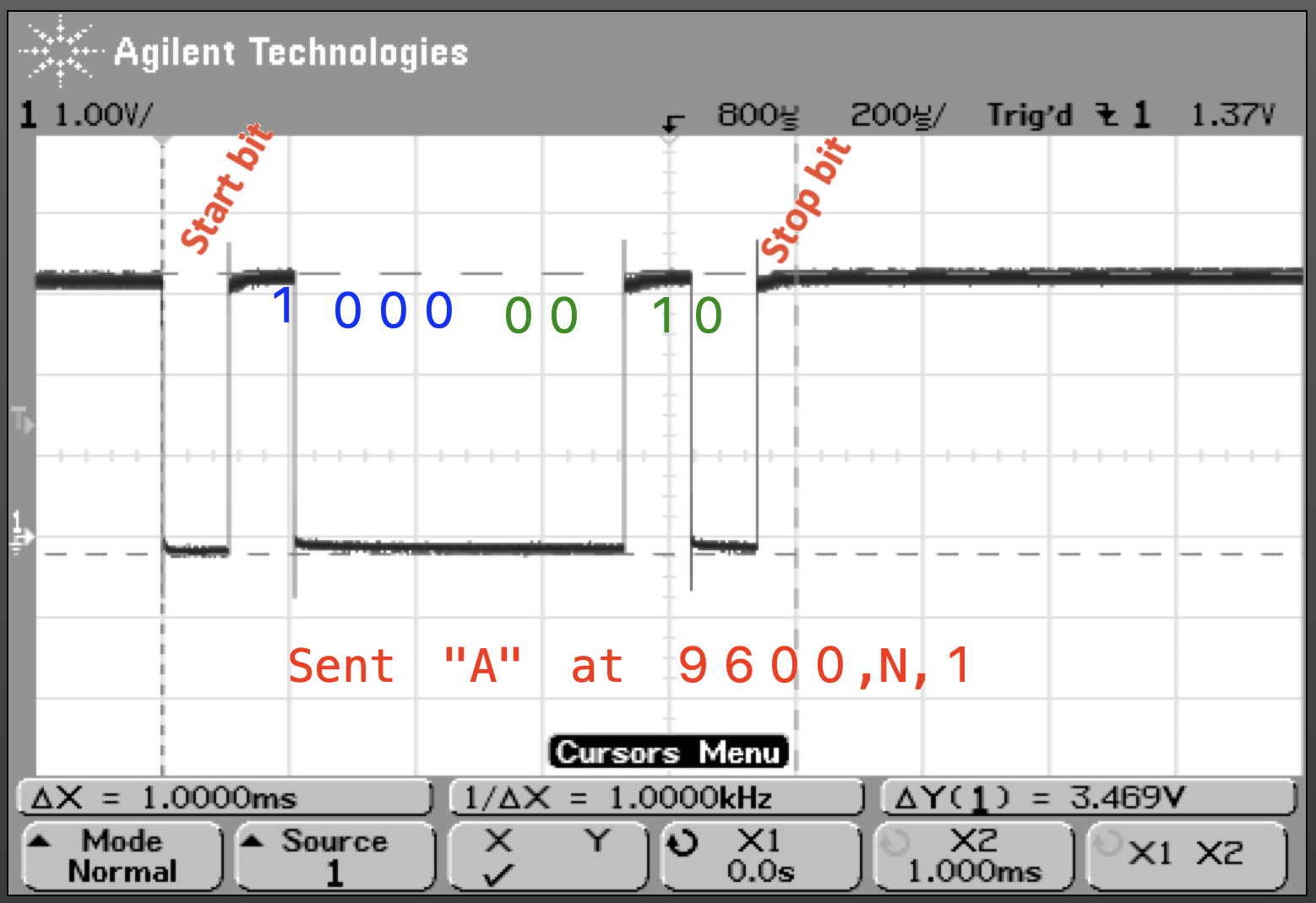
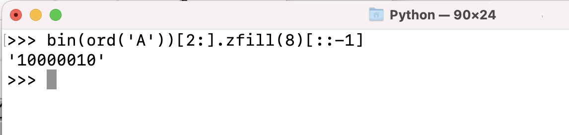
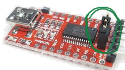
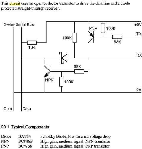
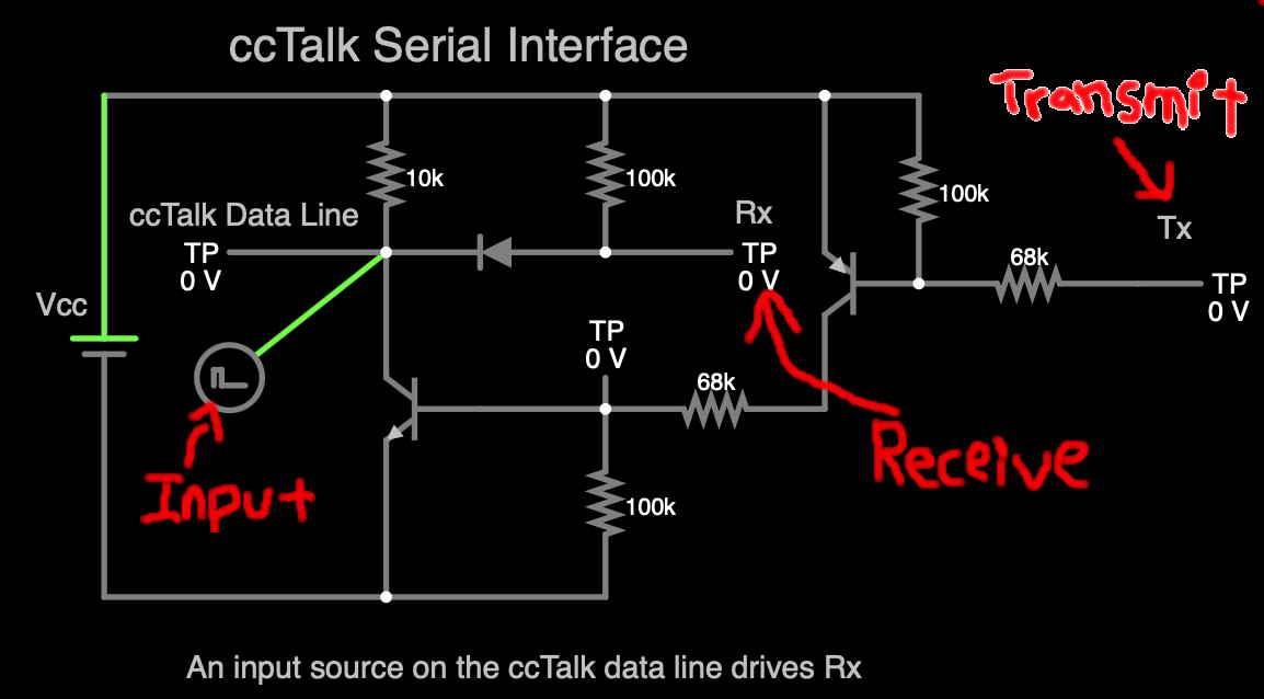
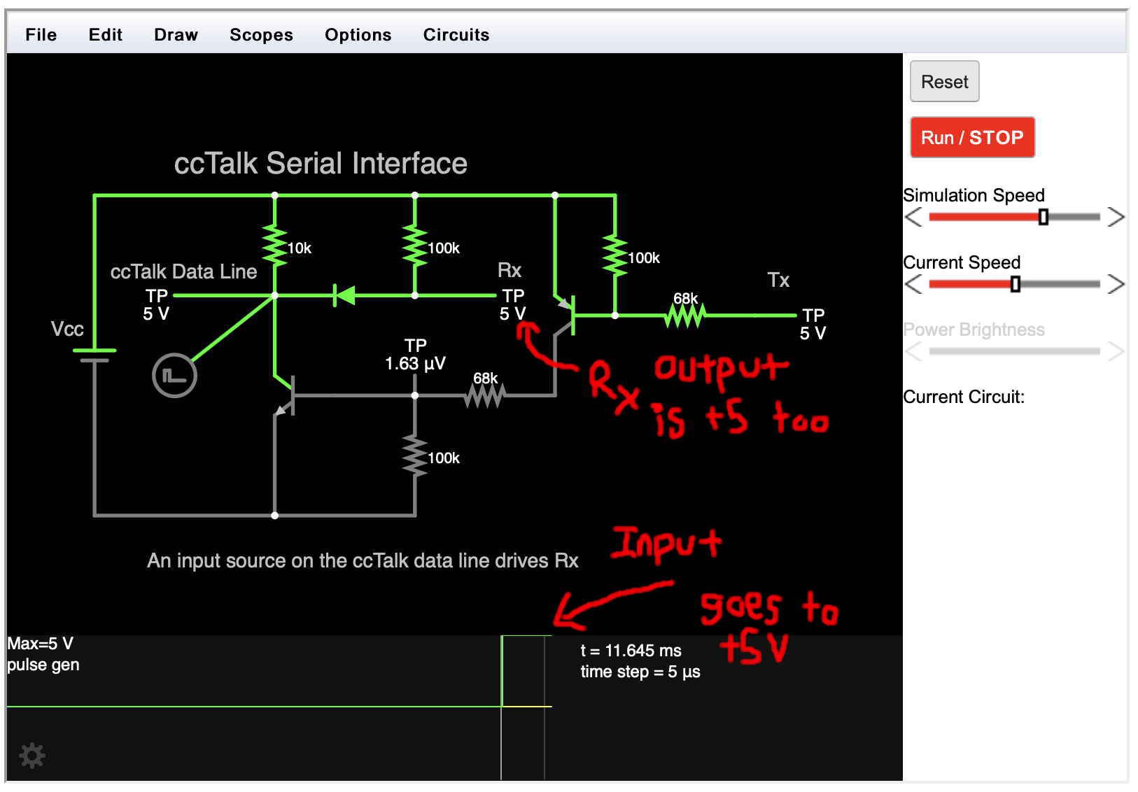
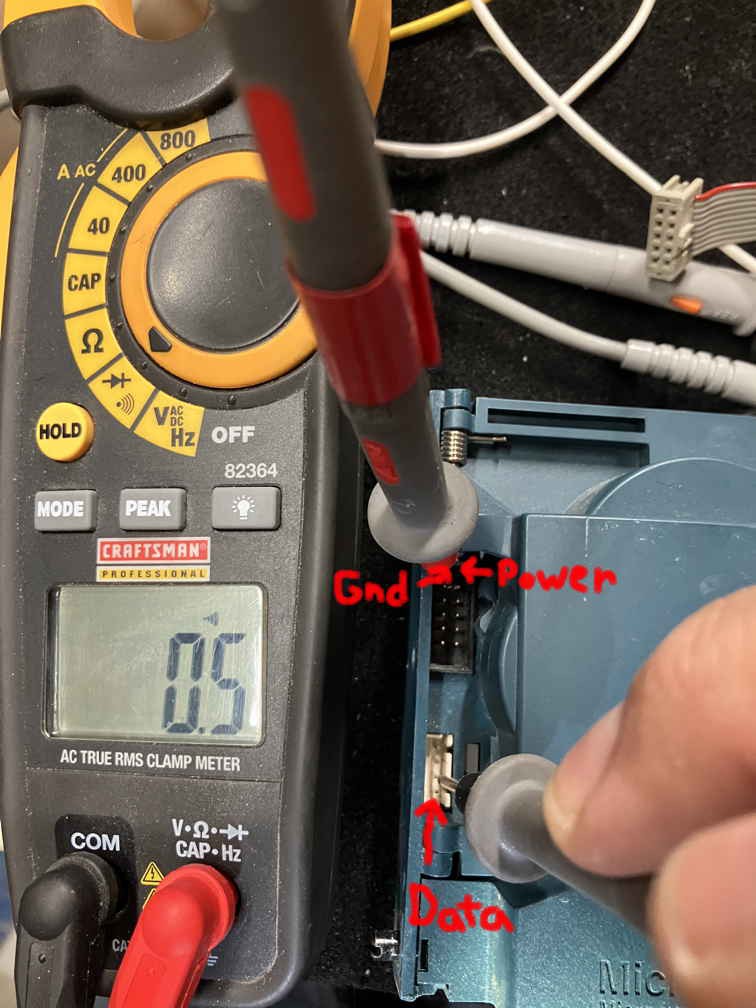
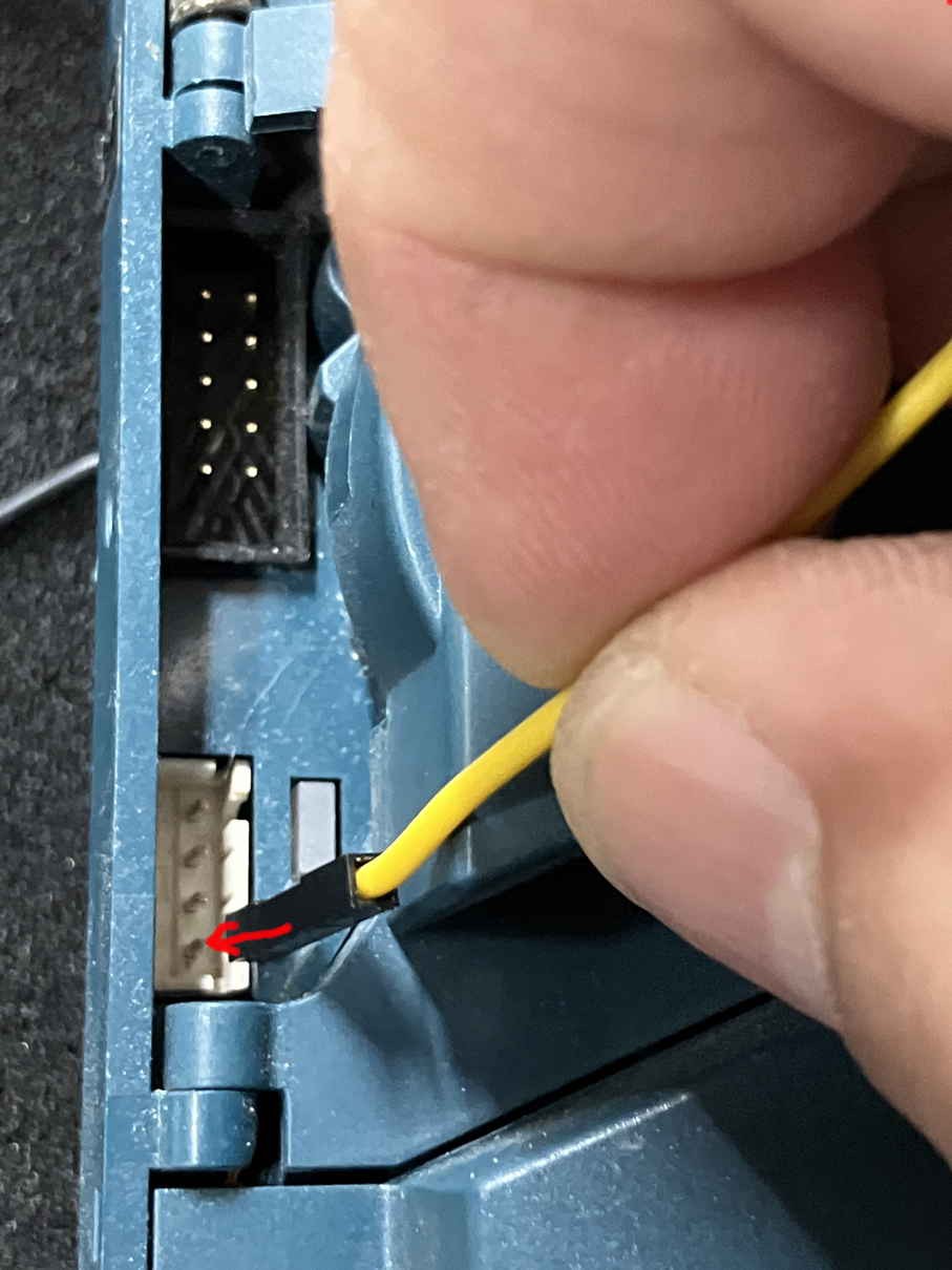
To enable a coin acceptor (e.g., my Microcoin QL Q5232), you will need to create (buy) an interface circuit, ground the 'inhibit' pin, connect a serial adaptor, use a terminal program (or a specific utility tailored for coin acceptors), and start polling the acceptor. That is, repeatedly send five bytes: 2 0 1 229 24.  The coin acceptor then connects to your vending machine, Gaming, or pinball :-) via the 'parallel connector' which pulses a coin line, for example coin5, for applicable credit. Conversely, controlling software could monitor the poll, parse the response, and account for any coin drop(s).

Word of caution: There is a difference between sending a "simple poll", that is command 254, and polling. Command 254, the simple poll is like a "TCP/IP ping". You simply get an ACK back if the acceptor is on-line. Whereas, "polling" is a process where you send command 229 over-and-over again.  So repeating 229, the read buffered credit command is what keeps the acceptor enabled/working.

As I spend countless hours digging through the ccTalk specification, manufacturer's documents, various forums, screenshots of specific utilities (of which many .exe's are no longer available),  and the source repositories of others who have been here before, it was clear that interfacing with a coin acceptor was already well know. Hopefully, I have said the same thing, but in way that is more readily consumable. I hope you enjoy reading about my adventure.

This has all been done before, even on Hackaday:

 https://hackaday.com/2013/08/20/hacking-coin-collection/
 https://hackaday.com/tag/coin-acceptor/
 https://hackaday.com/tag/coin-slot/

  • 1 × Microcoin QL A coin acceptor
  • 1 × RealTerm A serial terminal program for engineering
  • 1 × Falstad A circuit simulator
  • 1 × AtMega168

  • Brief Update

    Mike04/04/2024 at 01:22 0 comments

    I integrated my breadboard (the ccTalk interface), dusted off an AtMega 168 from grad school, and finished the code to poll my coin acceptor. I'm wrapping this project up. I will post more shortly.

    TL;DR

    Oh darn, I neglected to get a picture of the breadboard, the m168, various screen shots, and the green light on the coin acceptor. I also need to show multiple coins being inserted, and intermixing good and bad coins. So much tech fun.  I love it when a plan comes together. To be discussed in the Next post.

    For now, let me show the startup screen of my program. After a successful ccTalk Simple Poll command (P), a confirming checkmark ✔︎ is shown,  the serial number (SN) is extracted, and the master inhibit and the coin inhibit is queried. If good, another checkmark is shown next to ON. The result of the Read Buffer command is shown below the status line; notice that the coin acceptor starts up at event #1, no credits have been seen, and no coins (good or bad) have been inserted, and no coins (slugs) have been rejected:

    So there's not a lot of room on these Hitachi HD44760 screens. I spend more time trying to figure out how to condense the information a person needs to see and in a meaningful manner. But most of the time, what's seen is convoluted. For example,  I had to use "ON" to mean the device is not inhibited and there's at least one acceptable coin (not all coins are inhibited.) Again, an example of a tradeoff between space and information.

  • A Hello World for ccTalk: Send a Poll Command

    Mike02/22/2024 at 17:49 0 comments

    Bottom Line Up Front

    Send the following bytes: 2 0 1 254 255. This is a ccTalk poll command. Get an acknowledgement back: 1 0 2 00 253. Know that your coin acceptor is communicating with you. Try other ccTalk commands hereafter.

    TL;DR

    As my efforts continue, I acknowledge that this has all been done before. And nothing new to those in the industry. 

    So let’s begin by sending the ccTalk “poll command”, essentially “ping” by a different name. Above, the five bytes were presented: 2 0 1 254 255. Let me make two points:

    1. Bytes should be shown in hex. I should present: 0x02 0x00 0x01 0xfe 0xff. But RealTerm accepts either form, I’m lazy, didn’t want to type the prefix, so I'll show you decimal.
    2. Stating “poll command” and showing five bytes is technically incorrect. The five bytes actually comprise the ccTalk packet. The command is actually 254. The packet thus consists of the destination, 2, the number of data bytes, 0, the destination, 1, the (actual) poll command, 254, and the checksum, 255. Where the checksum is computed as 256 minus the remanding of the sum divided by 256, i.e., take the modulo operation by 256:   256 – (2+0+1+254)%256. I like using Python’s shell to quickly compute the ccTalk packet checksum:

    Note further, that Python only returns positive values when computing a mod; you can mod the inverse to get the checksum.

    To make a long story short, the result from the coin acceptor is an acknowledge (ACK) packet. The image of the command shows the poll and ACK in RealTerm:

    The sent poll command (packet), 2 0 1 254 255 is underlined in green.

    The ACK (response), 1 0 2 0 253 is underlined in blue.

    For brevity, I did not show how to set the baud to 9600 8N1, (eight data bits, no parity, 1 stop bit), nor my choice to show hex values + a space as my RealTerm setup.

    From here, it is a matter is issuing a variety of other ccTalk commands. Namely, those to retrieve information about the coin acceptor, and then setting values to control the device. And then hope there's no security controls (passwords / PINs) to restrict what can be done:

  • Started with PuTTY and then Switched

    Mike02/19/2024 at 18:00 0 comments

    Bottom Line Up Front

    I started with PuTTY; used its serial mode. However, it is not designed to send bytes. I immediately switched to RealTerm. That let me easily send a ccTalk poll command.

    TL;DR

    A few Google searches for escape sequences and ways to send raw bytes from PuTTY were not successful. It’s a great program just not meant for my needs. That said, PuTTY was already installed and its use gave me a chance to see the bits on-the-wire. I sent quite a few ASCII, A’s already. 

    RealTerm has a facility to raw bytes under the “Send” tab. Below you can see there’s two send-buffers. They accept either decimal or hex input. For example, I entered the ccTalk poll command, 2 0 1 254 255 (Strictly speaking, 254 is the command, 2 0 1 and 254 are the destination, number of data bytes sent, and the checksum respectively. More on ccTalk commands in my next blog entry.)

    Anyway, by clicking “Send Numbers” you can see the result in the display, and you will note that I prefer to see just the hex. This was previously configured under the “Display” tab by me, but not shown. Hopfully, that’s self-explanatory:

    Spoiler alert: Note the second input field, 2 0 1 229 24. The command 229 will be used to continually poll the coin acceptor, keeping it enabled and working. For now, let's continue.

    Before I show the result, that is bits-on-the-wire, I placed a probe at the serial Tx line (probe 1) and then on the ccTalk data-line (probe 2):

    My (eventual) intent and rational for this probe placement was to see a short command being sent and then more bytes at the data-line (that is, both the PC’s data and that from the acceptor). I’ll show that in the next post. For now, let’s see the bits for just the ccTalk poll command:

    The figure above shows each of the btyes sent ( 2 0 1 254 and 255) and that they’re reflected (seen) at probe 2 (on the ccTalk data-line.) Everything is looking good! Let’s power-up the coin acceptor and with luck, we’ll see a response.

  • Adding an LM311

    Mike02/19/2024 at 17:07 0 comments

    Bottom Line Up Front

    Use the right serial adaptor; one that supports the prerequisite voltage in your project. Or in my cast, grab an LM311 and stick it up front.  

    TL;DR

    Please understand that this was a rapid prototype. I have spent a factor more documenting what I did than actually getting it to work. Inserting a voltage comparator in front of the ccTalk interface kept the adventure going forward versus buying then wait for a dual voltage USB serial adaptor. Conceptually, this is what I did:

    And we can see on the oscilloscope that the 3.3V signal (an ascii “A”) is normalized to 5V:

    Getting closer to actually sending ccTalk commands to my coin acceptor!

  • Breadboard the ccTalk Interface

    Mike02/19/2024 at 16:14 0 comments

    Bottom Line Up Front

    The ccTalk interface circuit. was built on a breadboard with a few components. This was straight forward. Well almost.

    TL;DR

    I substituted the following components for those specified. If it didn’t work, I’d have simply ordered the right part. But since the resistors were really only being used as switches, and the resistors only being used as voltage dividers, I was fairly confident it’d work:

    Component

    Specified

    Substituted

    Schottky Diode, low forward voltage drop

    BAT54

    1N5817

    NPN, high gain medium signal transistor

    BC846B

    2N4400 general purpose

    PNP, high gain medium signal transistor

    BCW68

    2N4403 general purpose

    Resistors ¼ W

    68K

    57K

    And the breadboard:

    And it did not work. Recall that my serial adaptor only outputs 3.3V. The interface circuit is designed for 5V. Now, I could include an image of the wonky signals from the oscilloscope, but let’s move along. I inserted a voltage comparator in between the adaptor’s Tx and the Tx of the ccTalk interface circuit.

  • Just Buy It

    Mike02/19/2024 at 12:51 0 comments

    Bottom Line Up Front

    As an engineer, one must recognize when it is more cost effective to buy the solution vs. build your own. To that end, I researched the company’s Micromate and VAL 364 USB interface. Both are used to control the coin acceptor. Both are no longer available (or at least not readily available) so the adventure continues.

    TL;DR

    A little Goggling reveals two products: a Micromate and a VAL364. The Micromate was a handheld device that let the operator set, change, program and test the coin acceptor. The VAL 364 was an interface device, likely a serially adaptor that incorporated the ccTalk interface circuity. Both are discontinued. Here’s a picture of both cut-n-pasted from their product manuals:

    The VAL364 is shown in a [QLTalk manual]. QLTalk? That seems to be a GUI program used to control the coin acceptor. One quickly realizes that its capability matches that of the Micromate handhelp. Perusing, the program lets an operator extract the acceptor’s settings, change settings, program new coins, and run some diagnostics. The similarity undoubtedly stems from the underlying ccTalk; it being a developer’s API.

    Now, I also recognize that some ccTalk commands might be locked from my access (security by a password/PIN) and there might be some vendor specific commands (i.e., not discussed by the ccTalk specification) for which the structure will remain unknown. But, I should be able to duplicate the functionality of these devices.

    As for the products and just buying one,  neither seem to be available; they weren’t available from the company’s website, product distributors, or vending machine suppliers. One may appear on  an auction site someday. In the meantime, the adventure to do it myself continues.

  • USB Serial Adaptor

    Mike02/16/2024 at 16:08 0 comments

     Bottom Line Up Front

    Was it a $5 part? I don’t recall. It’s just a USB serial adaptor. Look mom, there’s a Tx and Rx pin. What more is there to say? Next.

    TL;DR

    My point: We should not take our systems, devices, and components for granted. It’s ok to know what they do and how they work. I take a moment to reflect on the ubiquitous (forgotten) serial adapter.

    Ah, the good-old DB9 serial port of yore is long gone; won’t ever return to a computer near you. And while USB has thankfully put an end to RS-232 serial, the interface still lingers, including its use in my coin acceptor… Yeah lingers, you and I still have/use a USB serial adaptor. Truthfully, I don’t even give much it thought. When it arrived, I don’t even think it came in a bag. It was cheap and certainly did not have any instructions. Still, these little adaptors remain a part in our hack-a-day lives. Just download the driver, make sure your (Windows) device manager recognizes it, select the comms port, set the baud in your terminal program (ccTalk uses 9600 N 8), and you’re good to go. Well not exactly, if I had a dollar for each time a serial connection did not work, I’d be … 

    Anyway, I’ve taken my adapter for granted. I plug it into the USB port. And let the half-inch long pins hang over the edge of the table. Connect some micro grabbers to the Tx and Rx lines, and then to the Rx and Tx lines (flipped) on the other device. (What we used to call the DTE and DCE in the old days. BTW, I like the Ponoma Micro grabbers.) I then move on with the project without much thought. Here’s a of my serial adaptor hanging over the edge. Sketchy sure. A hack, yeah:

    Again, I’ve forsaken my adaptor. It’d been a long time since I looked at its waveform. So let me hookup an oscilloscope and show the transmission of an “A”:

    How did I get (see) an “A”… Well, the ASCII value of “A” is 0x41, or 0b01000001 in binary. Notice that the LSB is sent first. Sent reversed. Finally, here’s a neat little trick in Python to print the reversed binary of your favorite character:

    Looking at that line of code, I could have done it faster via man ascii, looked at the hex, and flip the bits in my head.

    ☞ And that’s when I saw a problem. The oscilloscope shows the signal is about ~3.3V. Yet, the ccTalk interface circuit and likely the coin acceptor uses 5V. I had to address this issue! More on that next.

    Seems that I bought the cheapest adaptor; one that cannot switch between 3.3 and 5 volts. I should have gotten an adaptor with a selectable voltage:

    OK, serial adaptors: So cheap. So cute. So ubiquitous. So forgotten

  • Simulate Before Building

    Mike02/16/2024 at 14:13 0 comments

    Bottom Line Up Front

    Falstad is an on-line circuit simulator. It was used to simulate the ccTalk interface. The simulation confirms that the circuit couples and decouples data sent and received on the ccTalk protocol’s single data-line.

    TL;DR

    Measure twice cut once. While I am not building a wood cabinet, I believe the saying still holds. These days, you can simulate circuits on a laptop while watching TV. We truly live in a great time. So before I build the circuit with real components, let me simulate first.

    A quick recap: ccTalk is a protocol that lets a host like a PC or vending machine communicate (serially) with its coin acceptor. The protocol uses a single wire to transmit and receive data. The ccTalk specification thus, provides an interface to couple and decouple the transmit and receive signals from your (RS-232) serial adaptor. Last, the protocol uses +5V for the Mark state and 0V for the Space state. I found these class notes from U of Wisconsin on the basics of serial communication helpful. [ECE353

    Let me re-post the ccTalk interface circuit; it's from part 3 of the ccTalk specification:

    And its representation in Falstad:

    Here, I show three Test Points (TP): The ccTalk’s data-line, and the UART’s Rx and Tx lines. Note that that the input is an impulse function. It slowly steps between 0 volts and +5 volts, so we can see the what happens at Rx and Tx.

    When the input goes to +5 volts, Rx is also at +5 volts. Observe that the Rx Test Point (TP) is 5V:

    And when the input goes to 0 volts, Rx follows: Observe that the Rx TP is now at 0 volts. OK, pretty darn close enough to exactly 0. Last, the tool depicts the impulse function is as a green-rectangle along the bottom. I think Falstad calls it a 'scope':

    Of course, if the simulation runs for a longer time, the input (OK scope) on the data-line will alternate between +5 and 0 volts (logic 1 and 0). So why use an impulse function? It simulates the eventual transmission of arbitrary binary data by a coin acceptor. ??? Imagination, while the function just goes 101010... I imagine it being arbitrary data.

    ☞ Clearly, we want the Rx line to track what the coin acceptor is sending on the ccTalk data-line. However, I observe that the Tx line is also following the data-line. Now I’m a software guy, and am assuming that this is OK. That Tx is only a transmit register, that the UART’s circuitry is capable of sinking current placed on  its Tx pin (there’s a 68K ohm resistor, so not even a 1mA.)

    Finally, lets track what happens when the UART transmits. Below, please notice that the impulse function was moved to the Tx Test Point (TP). It still cycles between +5 and 0. As expected, when a +5 is sent, the data-line is also at +5.

    ☞ Like I mention above, please note that the Rx test point tracks what is on Tx. I assume that this is OK. When the UART is transmitting, it won't accept (read) the data on its Rx pin. Yeah, I realize that a serial connection might be full-duplex. So the UART might re-read what it sends. But for now, I must assume the designers of the protocol knew what they were doing and use what they offer.

    Ok, the post is getting quite long. So instead of showing that no voltage at Tx is matched on the data-line, let me just Post my Falstad file.

    I’m close. I’m nearly ready to hookup the computer, it’s serial lines, the interface circuit, and the coin acceptor. But first…

    The link to the Falstad circuit simulator:

      http://falstad.com/circuit/

  • The ccTalk Interface Circuit

    Mike02/16/2024 at 00:47 0 comments

    Bottom Line Up Front

    CCTalk uses a single data-line to transmit and receive data. An interface circuit is needed before connecting with your PC’s serial port. Let’s talk about alternatives, the actual circuit and then breadboard one. 

    TL;DR

    Directly from part 3 of the specification:

    And we can graphically show where the ccTalk interface circuit goes:

    Note then, that you use RealTerm (a program on your PC), a USB serial adaptor, wires for the transmit and receive wires, the circuit, another wire for the ccTalk data-line, to connect to the coin acceptor. Easy Peasy.

    Ok, ccTalk uses a single wire to transmit and receive (serial) data.But, I don’t think you can just twist your serial port’s Tx and Rx lines together and then wire them onto the ccTalk data-line. That said, there’s a YouTube video that explains exactly how to do this: 

    I'll insert his link below.

    Further, there is a GitHub project to create your very own PCB. So cool, but I don’t think it’s necessary:

    So between the gentleman that ties his Tx and Rx lines and a custom PCB, I prefer to follow the specification. In fact, three levels of interface circuits are provided from simple to more advanced. But really it is not that advanced (the figure is from Part 3 of the ccTalk specification):

    Looking at the circuit, I have the resistors, a Schottky diode, and a bunch of random NPN & PNP transistors.  So let’s build this! No wait, let’s simulate the circuit first. Let’s use Falstad. 

    Reference the GitHub project

    https://github.com/srdjanStankovic/CCtalk-converter/tree/master

    Reference the YouTube video: ccTalk serial adapter

    https://youtu.be/CCpXqio99eg?si=nUEWGtZIPUpnjPvQ

  • Probing my ccTalk Port

    Mike02/16/2024 at 00:10 0 comments

    Bottom Line Up Front

    The data-line for ccTalk is on pin 4. The power and ground pins are on pins 1 and 3. Power and ground are identical on both the NRI connector and the ccTalk port. Like no-duh. Well, best not to make assumptions.

    TL;DR

    So I need to find the data-line for the ccTalk port. Reading part 1 of the ccTalk specification, we see that data is found on pin 4. And the directional locality (ok polarity) is also shown:

    So what does all this mean in the real: Where's the data pin. Well, power and ground were previously found on the 10 pin NRI interface. I know that ground is on pin 1 (upper left) and power is on pin 2 (upper right) in the 10-pin connector, that is the NRI interface (ok the black plug on my coin acceptor.) Grab the multimeter and look for continuity. The figure below shows the red probe on ground (pin 1) and a probe on pin 3 of the ccTalk port (ok white plug). There's continuity so data is the bottom pin:

    Currently, I supply ground and power via a 10-pin ribbon cable. I thus, use a simple connector to the data; just a wire from the parts bin and works good enough for my tests. As seen below, stick the silly connector on pin 4 for data. I will use this connector/wire when connecting the coin acceptor with my computer:

View all 15 project logs

Enjoy this project?

Share

Discussions

Similar Projects

Does this project spark your interest?

Become a member to follow this project and never miss any updates