Marek
MarekTheory of Operation
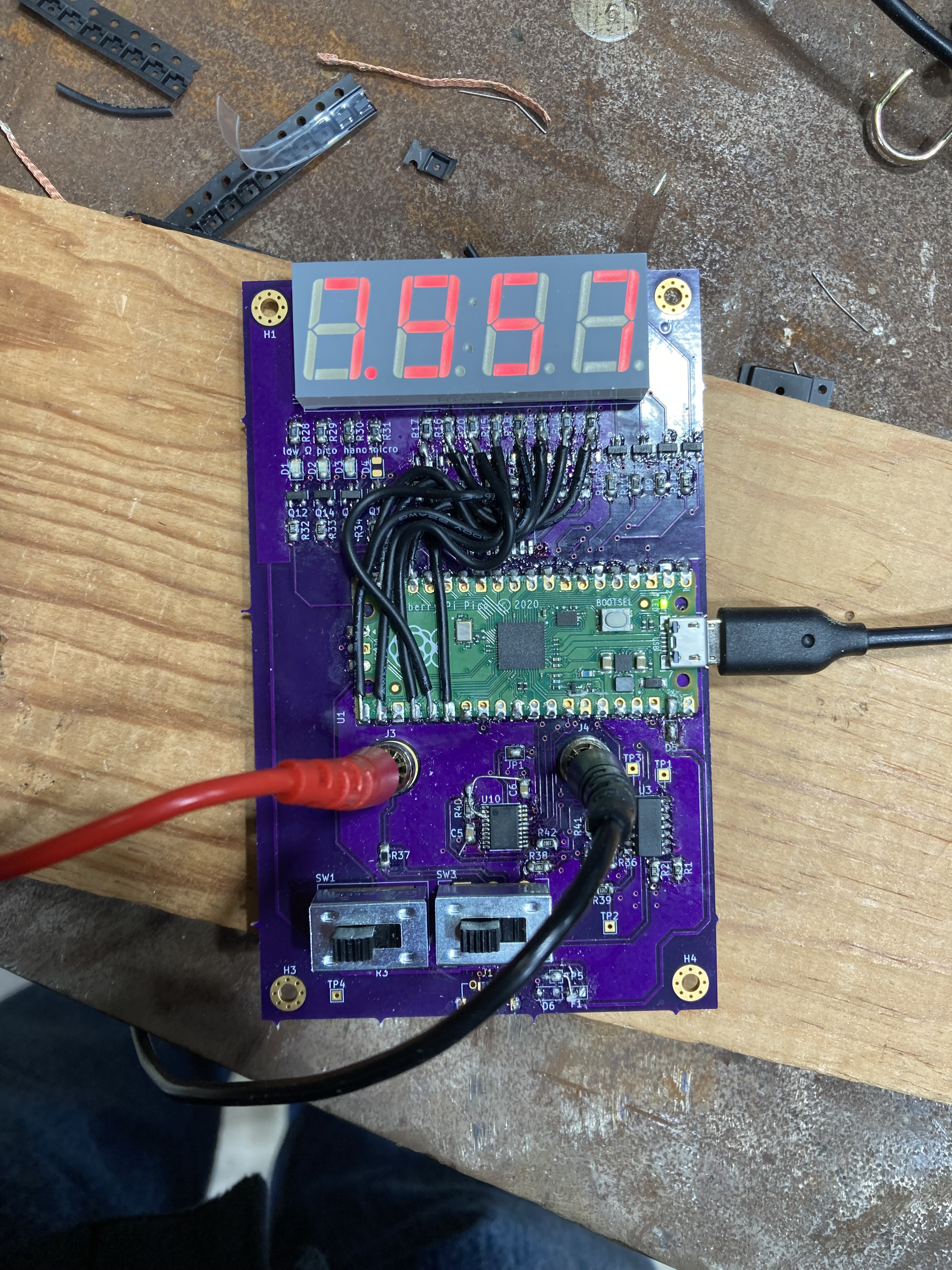
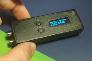
The multimeter is controlled by a Raspberry Pi Pico. This Pico reads digitized data from the front end, computes the voltage, resistance, or capacitance value, and drives the led display to display the value.
Display Driver
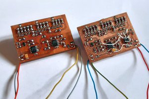
For some reason I could not find a chip that would just drive a 4 digit seven segment display that I could easily purchase. Maybe I didn't look hard enough, or maybe it doesn't exist. Instead I basically made discrete IO pin buffers from p-channel and n-channel mosfets. 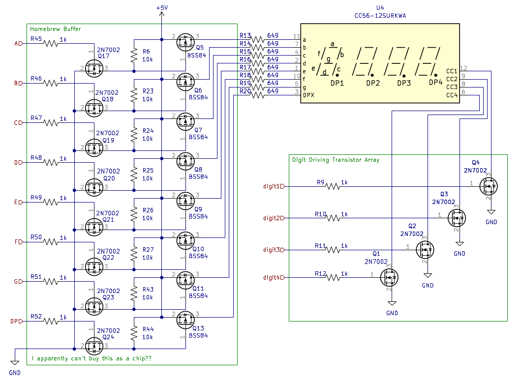
There are also four regular LEDs that indicate things like unit prefix and sign. These are not shown but can be found in the full schematic.
Analog Front End
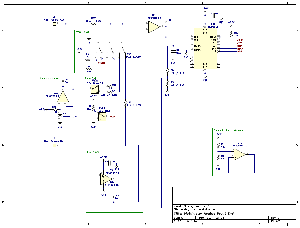
The analog front end conditions voltage readings that are read by the MCP3561 ADC. The conditioning circuit is selected by the various switches. When SW3 is in its default position, the meter is in voltage measurement mode. Switching it changes to component measurement mode. Changing between resistance and capacitance in component mode is facilitated by a logic switch wired up to the Pico (Not Shown). The range switch changes the range in component measurement mode.
Voltage Measurement
As can be observed, voltage measurement mode is a buffered voltage divider into the ADC. Another buffer floats this division at half the ADC reference voltage to allow for negative voltage reading. This floating of the measurement circuit is still there in component measurement mode, which is probably detrimental to performance.
Resistance Measurement
In component measurement mode, voltage is sourced by buffered 2.5V LM4030 voltage reference in series with the range resistor. There is also another resistor between the measurement node and the input terminal to provide some protection to the device. The combination of these resistors in series, and the resistance being measured creates a voltage divider and resulting voltage that is read by the ADC. The measurement resistance is then calculated in firmware using the known resistances and measured voltage.
Capacitance Measurement
Capacitance measurement is the same as resistance measurement except capacitance. This basically means that instead of measuring a static voltage, the voltage is constantly monitored for a dip that indicates a capacitor was connected. The resulting exponential rise is then sampled, and using the points from this sampling, the capacitance is found. All this computation is obviously done using the Pico. There is a trigger indicator to alert the user that they have triggered on a capacitance.
Improvements
The most lacking part of the design is probably the resistance measurement which only achieves 10% relative accuracy. The biggest issue with the resistance measurement is that it is using a ratio (series resistor) instead of a current source. This becomes a problem when the series resistor is very big compared to the resistance being measured. Additionally, the added series resistor in the network (Between the measurement resistor and the voltage reference series resistor) complicates the measurement algorithm and circuit.

 kevarek
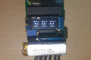
 Dr.Stone
 Alan
Alan