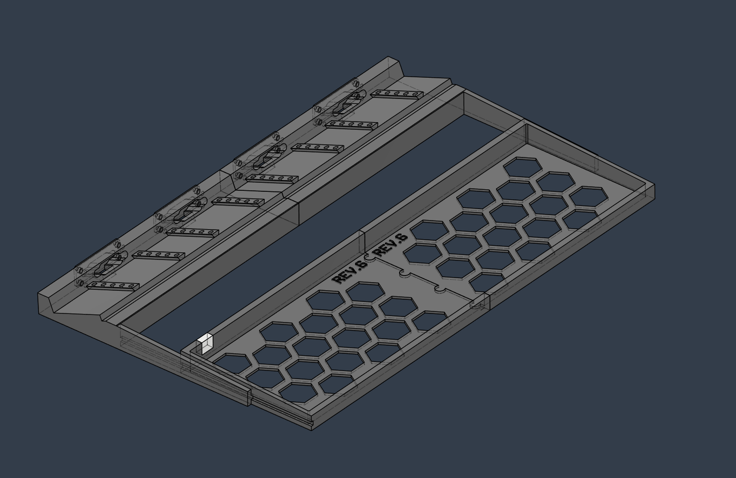
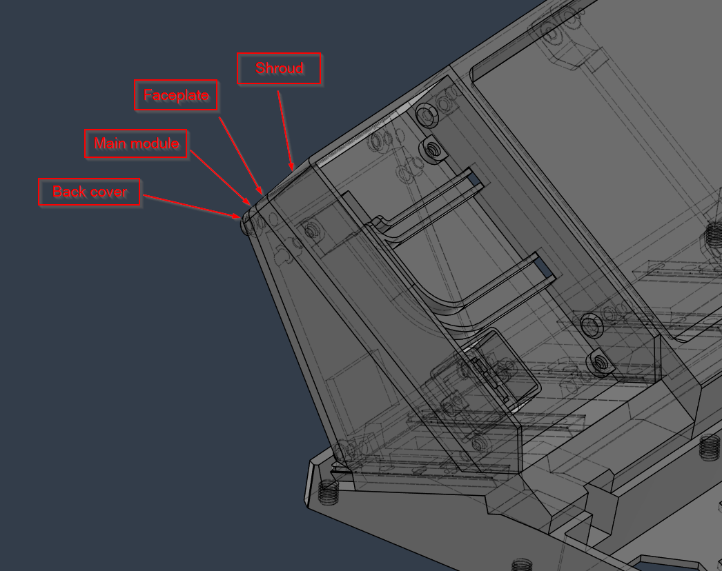
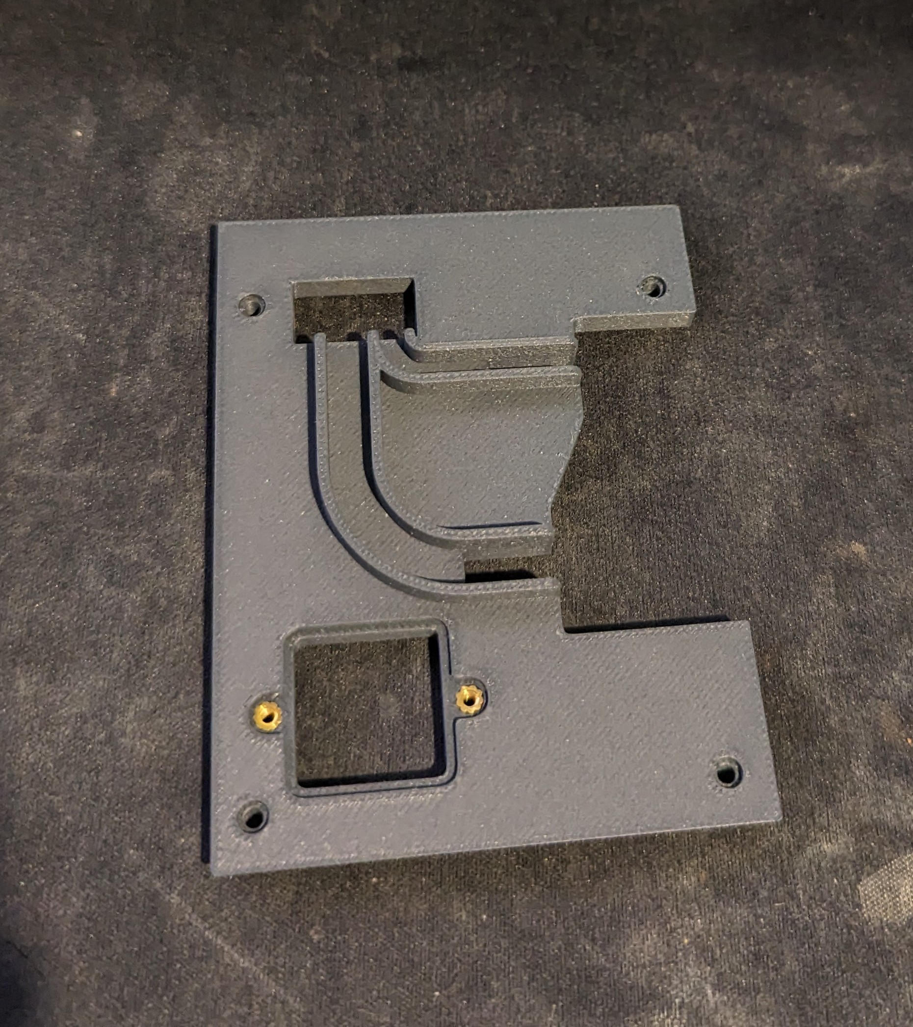
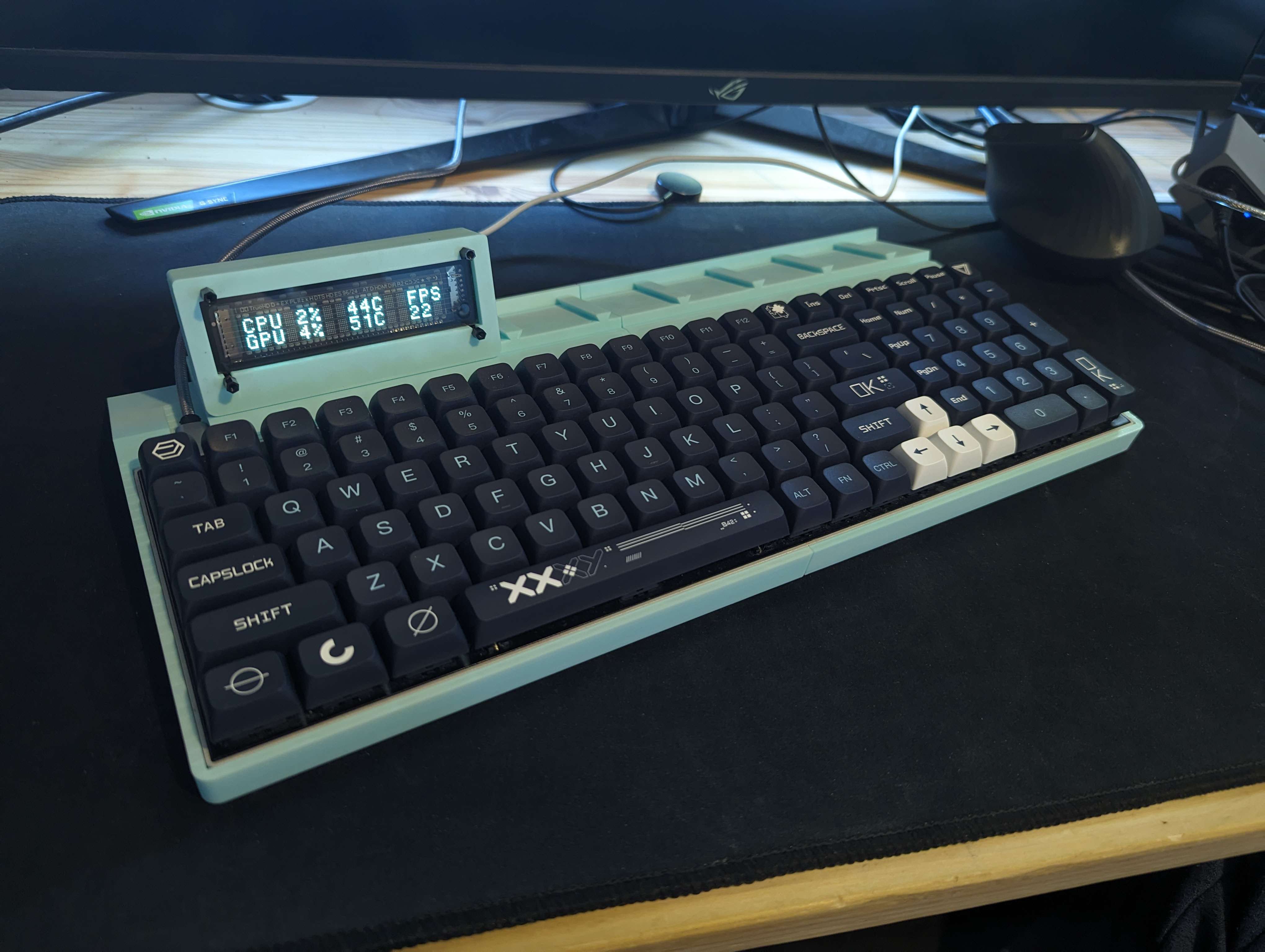
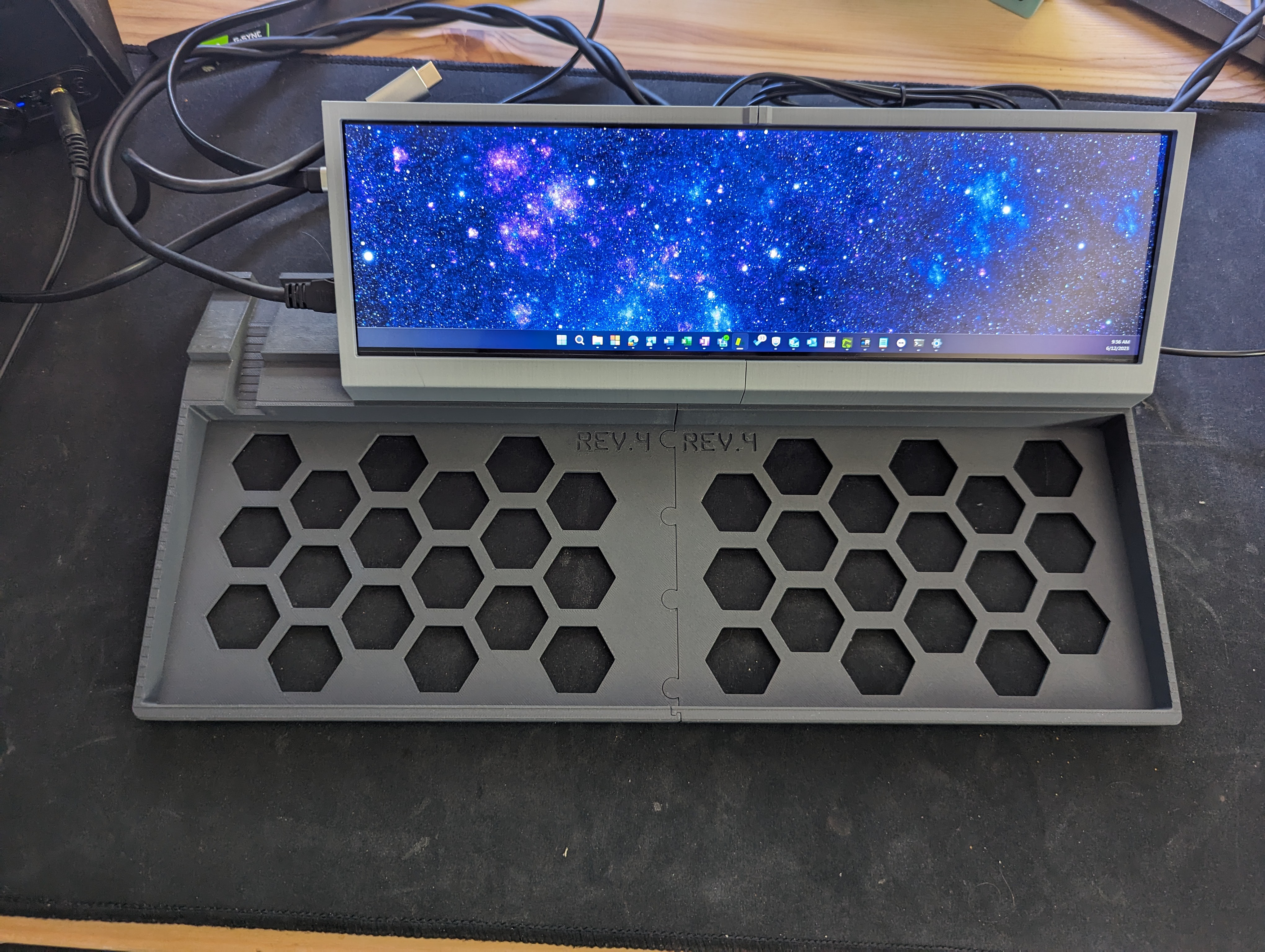
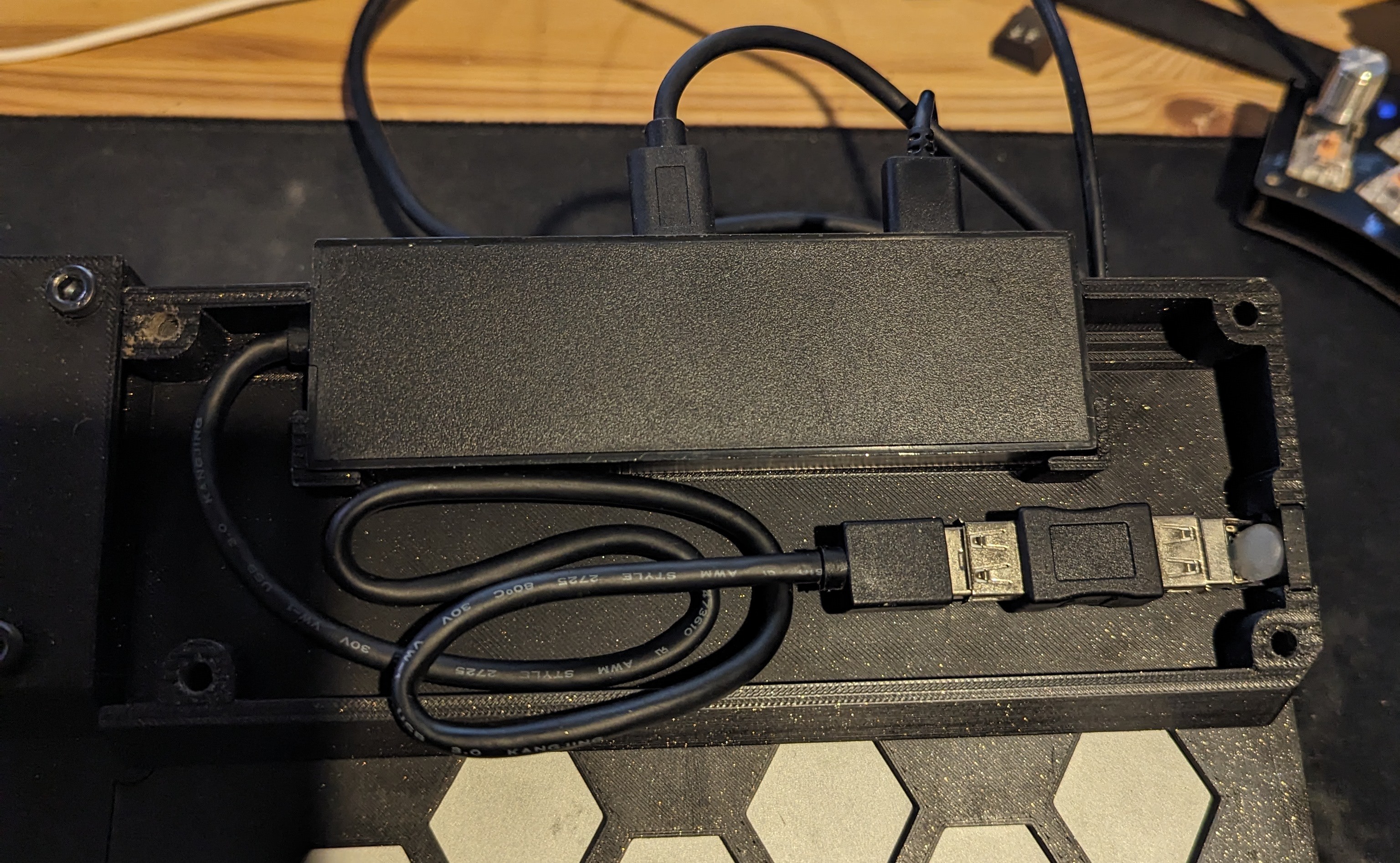
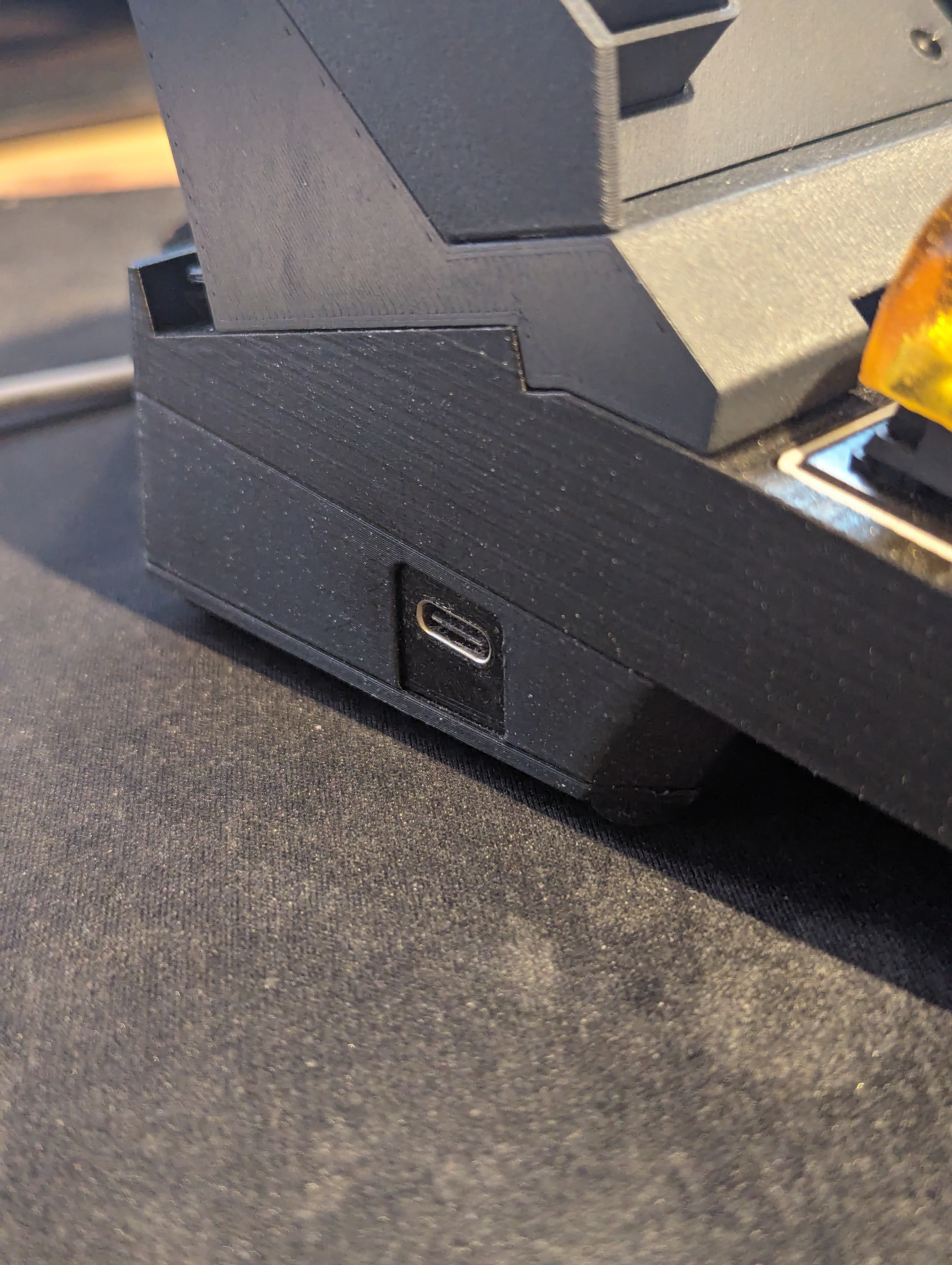
The main idea of the thing is a modular platform that primarily holds a keyboard and accepts modular components.
These are anything that makes sense to attach to a keyboard. Or, loosely make sense, even.
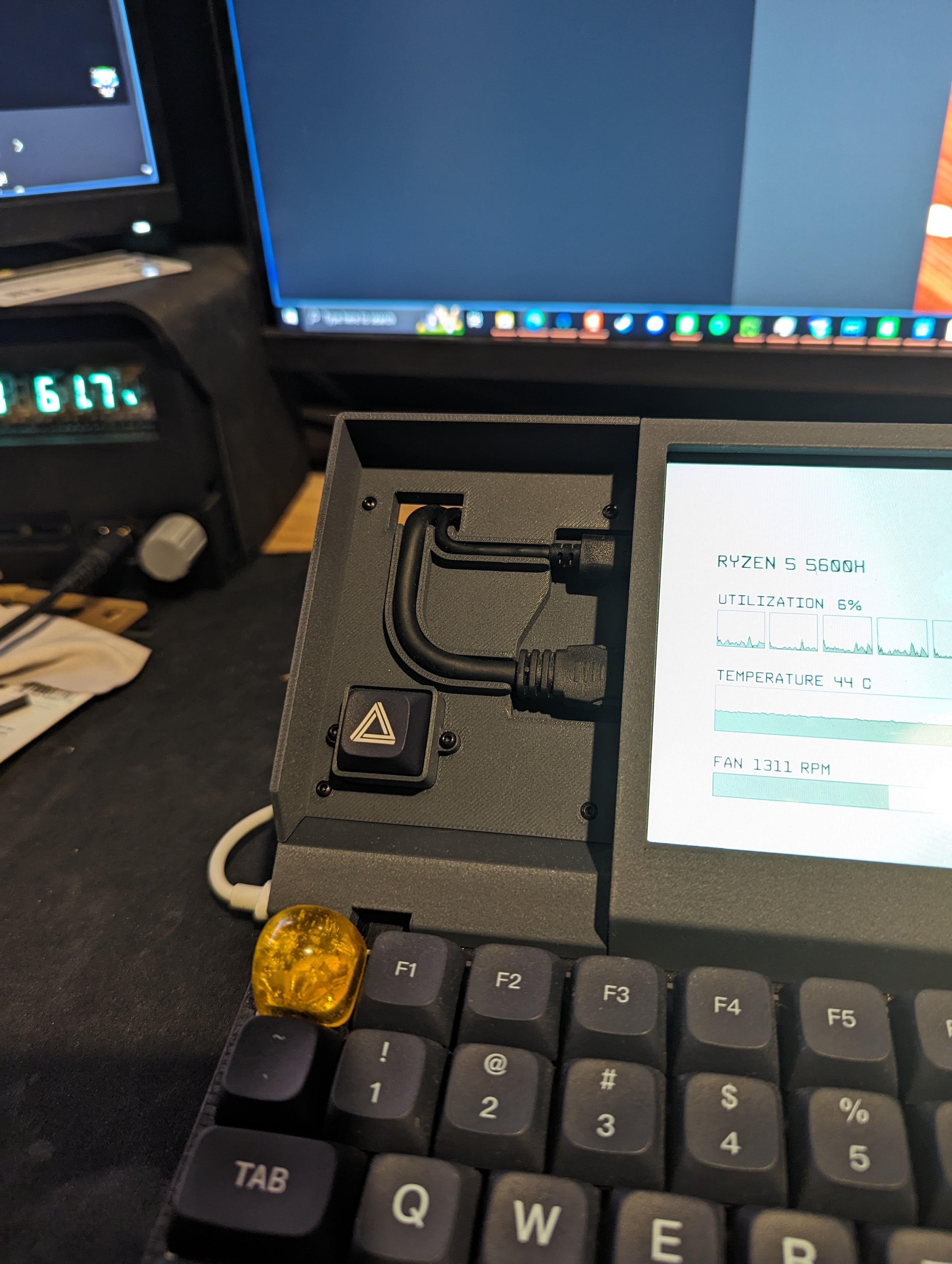
So far I have about half a dozen different modules.


 Brieuc du Maugouër
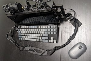
 knar
knar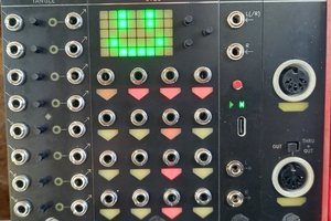
 David
David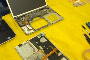
impressive work! I would love to do this but using an eink display but seems quite expensive