0%
0%
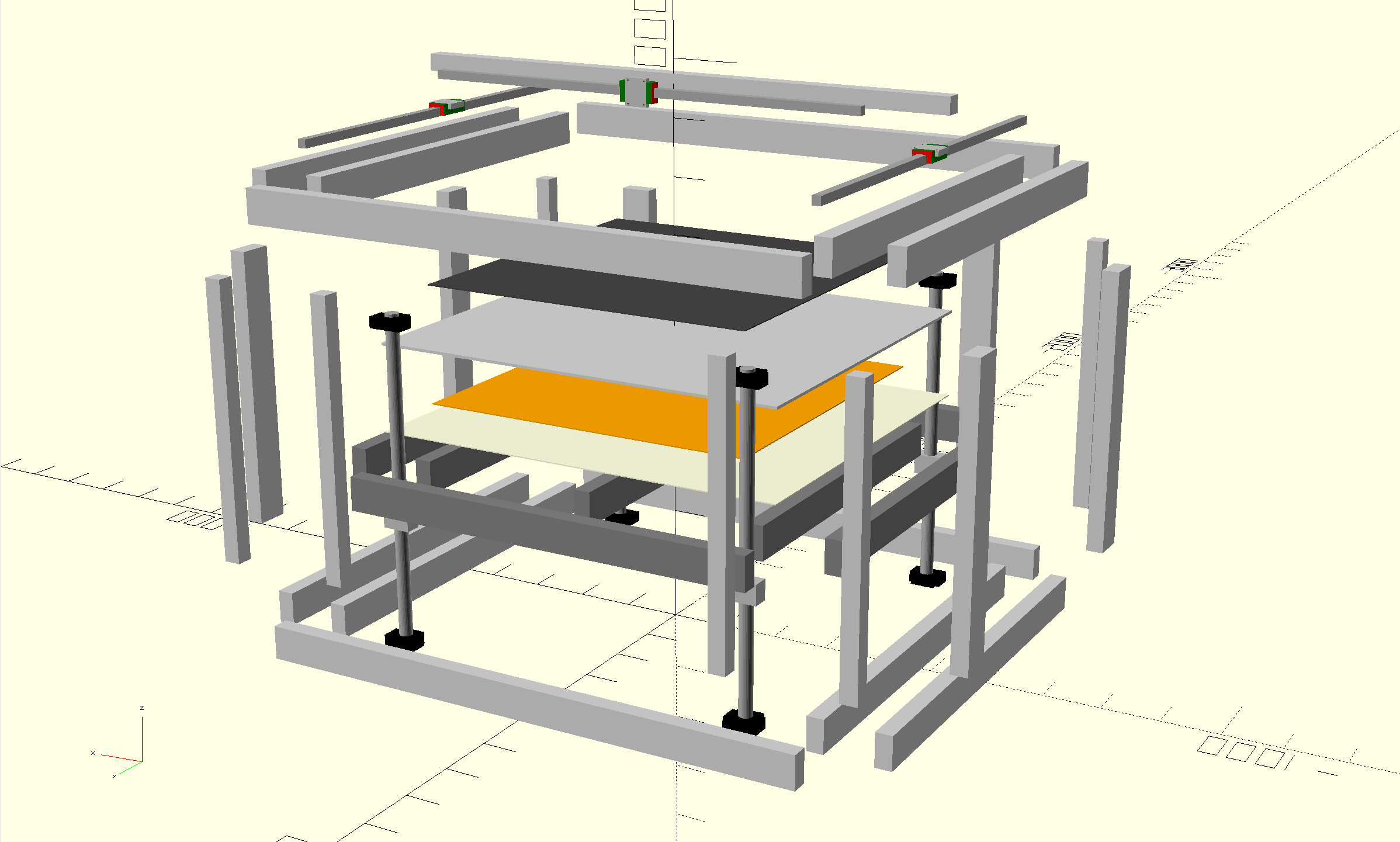
Bootstrap 3D Printer
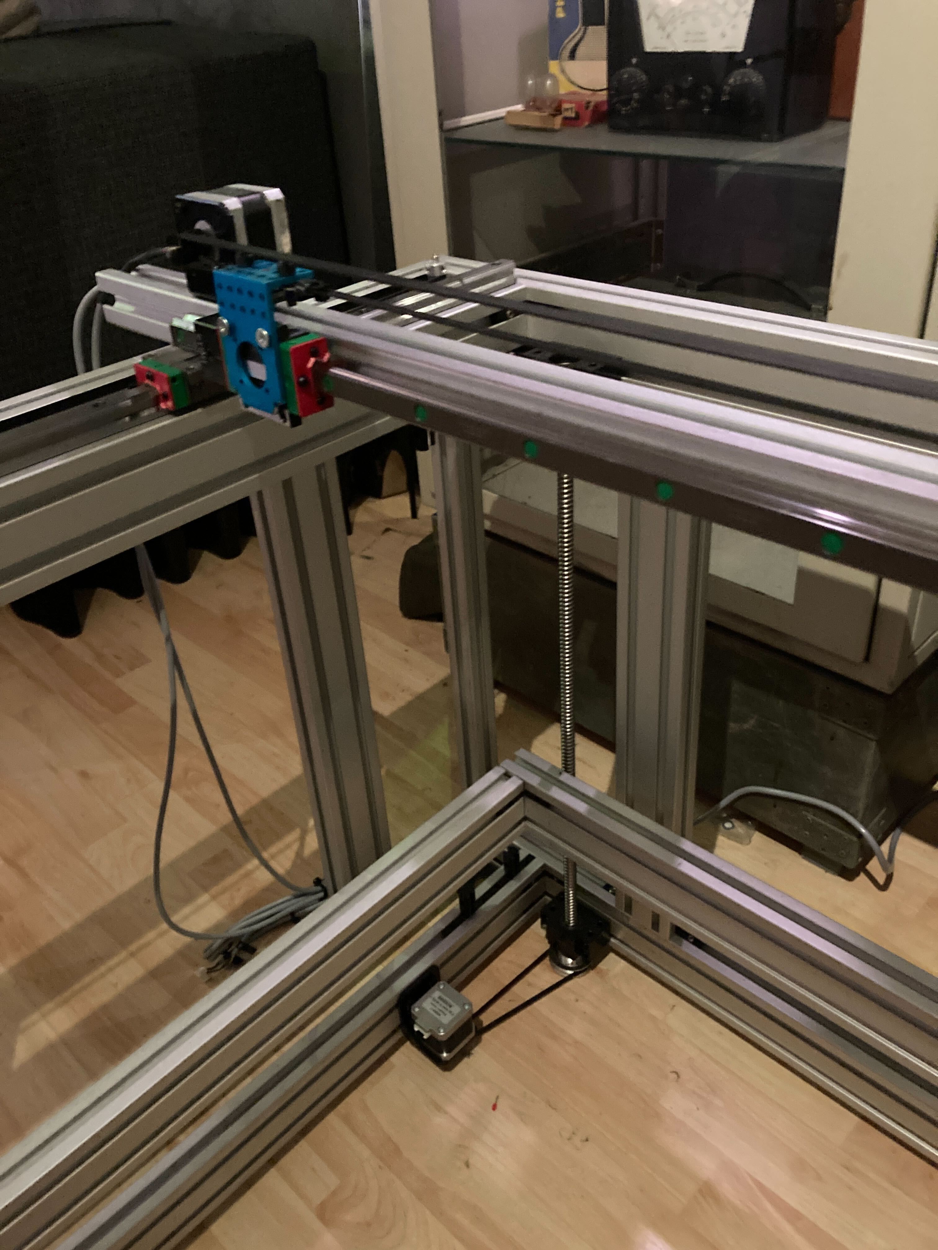
Bootstrap: A large volume 3d printer that can be built at home without requiring any custom 3d printed or machined parts.
 E/S Pronk
Become a Hackaday.io member
Already have an account? Log in.
Just one more thing
To make the experience fit your profile, pick a username and tell us what interests you.
Pick an awesome username
hackaday.io/
Your profile's URL: hackaday.io/username. Max 25 alphanumeric characters.
Pick a few interests
Projects that share your interests
People that share your interests


 Cees Meijer
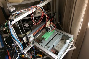
 Saabman
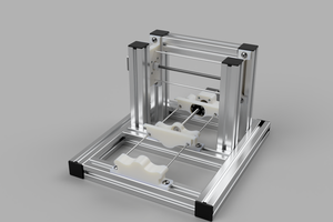
 Myles Eftos
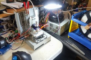
 AccidentalRebel
Solid project, love it!
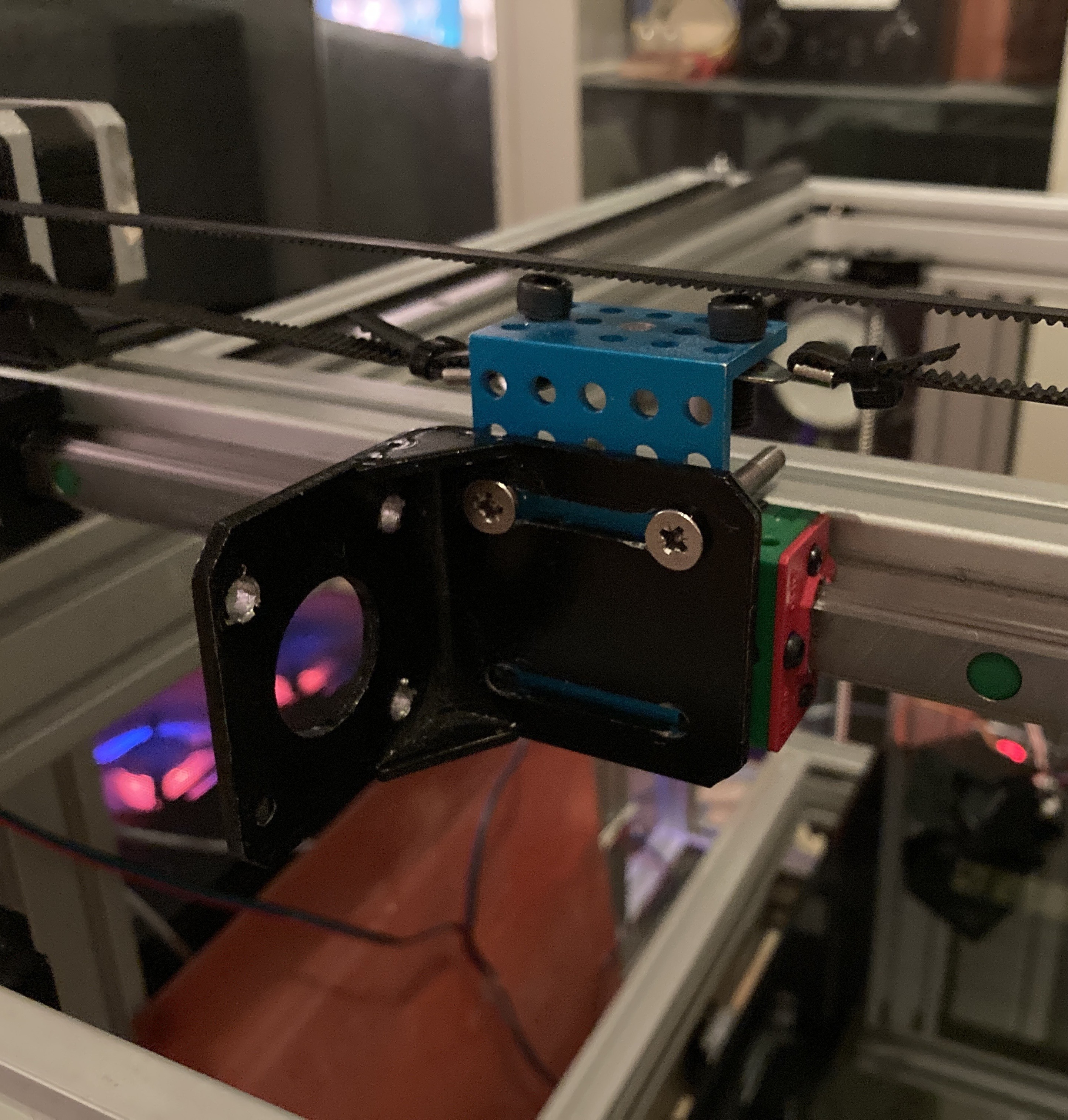
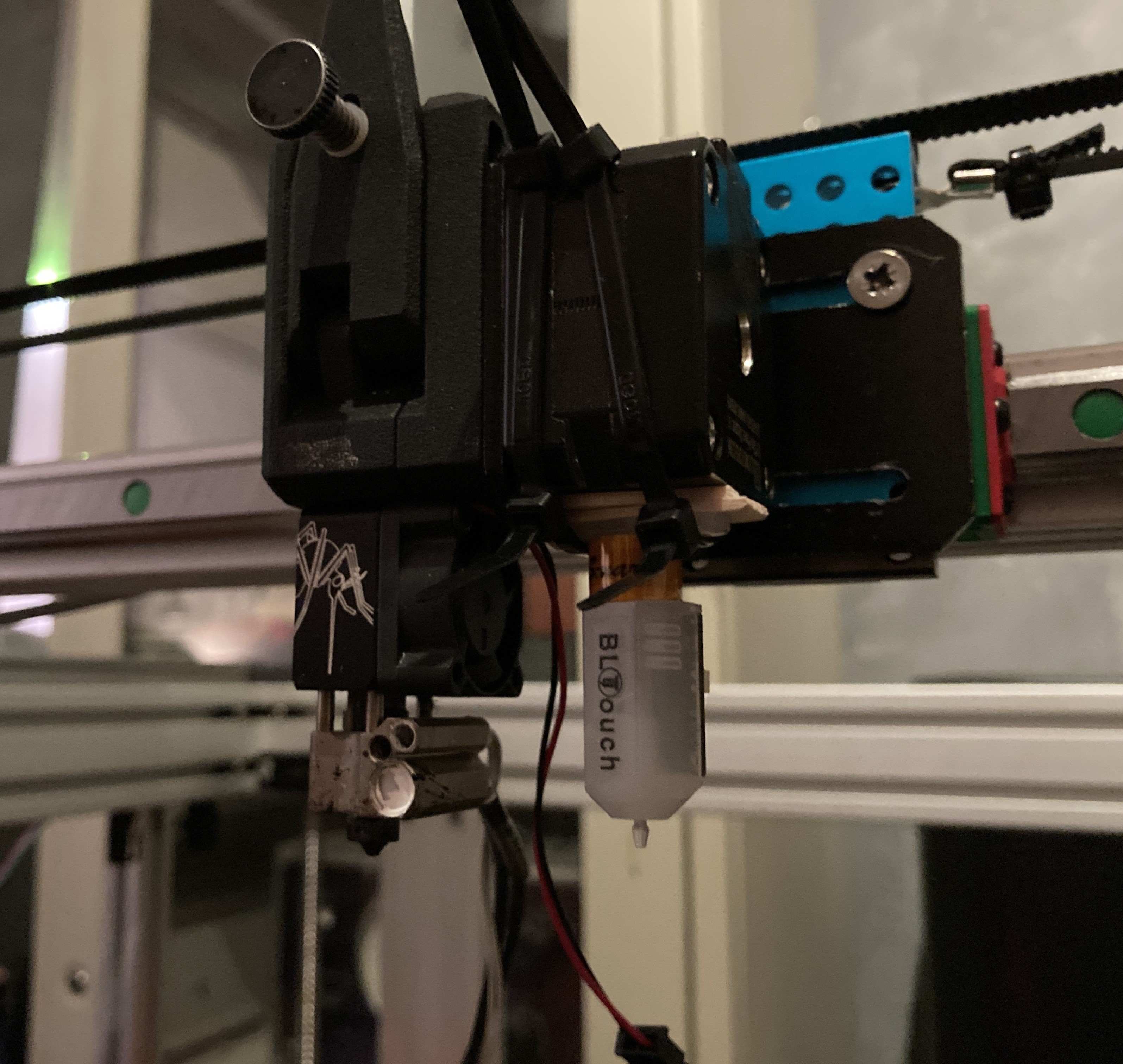
(you're probably adjusting belt tension via the motor mounts. I'll leave a link to my write-up on belt tensioning with a re-purposed hose clamp here for your enjoyment and inspiration: https://hackaday.io/page/7198-hose-clamp-style-gt2-belt-tensioners)