 Ella Jameson
Differences from the Adafruit Trinket M0
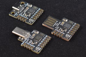
Some hardware was removed from the board, in order to make it even smaller. All features can be re-created with external components using the exposed pads.
- APA102 RGB LED
- Exposed pads S (7) and M (8) are the SCK and MOSI pins that were connected to the APA102.
- Exposed pads 3 (3.3V) and G (GND) are the power rails that were connected to the APA102.
- USB Connector
- Exposed pads + (USB D+) and - (USB D-) are the data lines that were connected to the microUSB port.
- Exposed pads 5 (5V In) and G (GND) are the power lines that were connected to the microUSB port.
- Reset Button
- Exposed pads R (Reset) and G (GND) are the pins that were connected to the reset button.
- These 2 pads are intentionally placed next to each other, so that it is easy to short them out with a metal object like tweezers.
- These are the 2 pads closest to the white circle near the bottom left corner of the board.
- Power LED
- Exposed pads 3 (3.3V) and G (GND) are the voltage rails that were connected across the LED-resistor circuit.
Inspiration
The idea for this board came from the numerous Nintendo Switch V1 modchips (payload injectors). Those devices started being made when people realized that a Trinket M0 could be used to run custom software on some consoles if you installed them onto the motherboard and loaded some special firmware onto them. Because the Switch has very little open space inside it, people started making and selling stripped-down versions of the Trinket M0 that were designed to be as small and easy to fit into the Switch as possible.
While that particular use case is pretty shady (and likely to get you in trouble with Nintendo), I thought the idea of an absolutely minimized Trinket M0 was really solid! Specifically, I immediately imagined using it for advanced circuit-bent musical instruments, possibly even being able to add MIDI over USB! Because these devices I mod are so varied, it's basically impossible to design a USB-based board that mounts universally. With this board though, I can separate the problems of fitting a USB port and fitting the MCU board. Plus I don't have to worry about desoldering the microUSB and then tacking on to its minuscule pads, I just have 4 big USB pads broken out and ready to solder to.
In terms of hardware compatibility, this chip is closest to the "Rebug SwitchME M0" modchip. Indeed, it should be directly compatible with any firmware written for that board. Of course, the pads are laid out differently, so make sure you check the pinout diagram before you start soldering.
No .uf2 firmware files are provided here, just the UF2 bootloader. An Arduino board definition file is provided to enable you to write your own code.
Disclaimer
THIS IS NOT A MODCHIP!!! THIS IS NOT A PAYLOAD INJECTOR!!! THIS IS NOT AN ANTI-PIRACY CIRCUMVENTION DEVICE!!!
While the form factor of this device is based on various Nintendo Switch "modchips", the intent of this device is to act as a general-purpose MCU development board specialized for use in new or existing custom electronics projects, and/or for new product research and development. This repository does NOT contain any hardware or software which enables the circumvention of any security or anti-piracy measures, on any device, by any means. The bootloader provided is a customized version of the Adafruit UF2 Bootloader which simply enables the MCU to be programmed directly over a USB connection (i.e. without an intermediate programming interface device).
It is the sole responsibility of the end-user to ensure that the hardware and software files provided in this repository are used lawfully. No further disclaimers or warnings will be provided.
 arturo182
 TheBrokenEngineer