 Arnov Sharma
POWER Pi Version 1
Let us explore the Power Pi that was previously constructed.
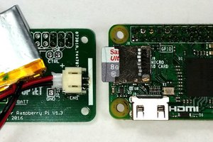
The primary component of the previous version was the power management board, which powered the Raspberry Pi board with four 3.7V 18650 cell holders.
In order to hold the power management board and Raspberry Pi together, we modeled a base and added a second Raspberry Pi holding part.
The configuration worked, but it had a few body-related problems that made it less durable overall. Next, there was a problem with the power management circuit, so we built our own battery pack using custom PCBs and installed two of them to power the Raspberry Pi in the updated version.
You can checkout the previous version at the below link:
https://www.hackster.io/Arnov_Sharma_makes/rgb-led-board-for-power-pi-2-4e7f7d
New Version: DESIGN

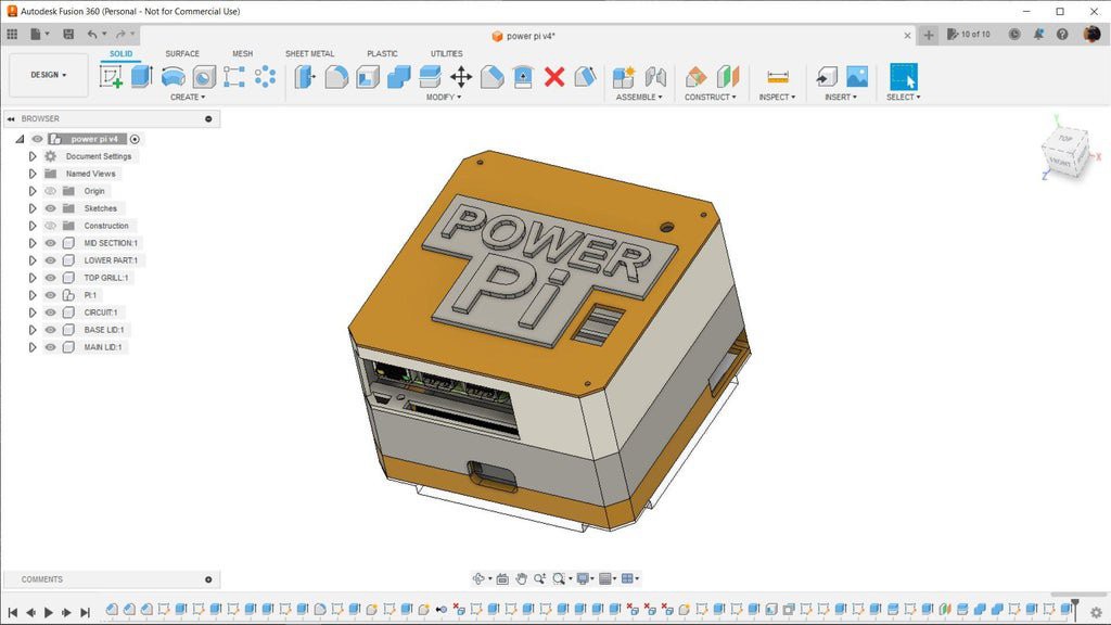
Given its five-section design, the Power Pi Version 2 is larger than its predecessor. The sections in question are as follows:.
TOP Section:
This is the top portion of the model, and it has two main components: the fan assembly part, which draws air into the Power Pi for air circulation, and the handle, which attaches to the outside of the top portion using two M3 bolts from each side.
To keep the Pi cool, a fan holder was added. This holds a standard small DC PC fan from the inside.
It is entirely redundant to add a fan, but if your workload involves more than just running retro emulators, do it in order to keep the Pi operating at its optimal temperature.
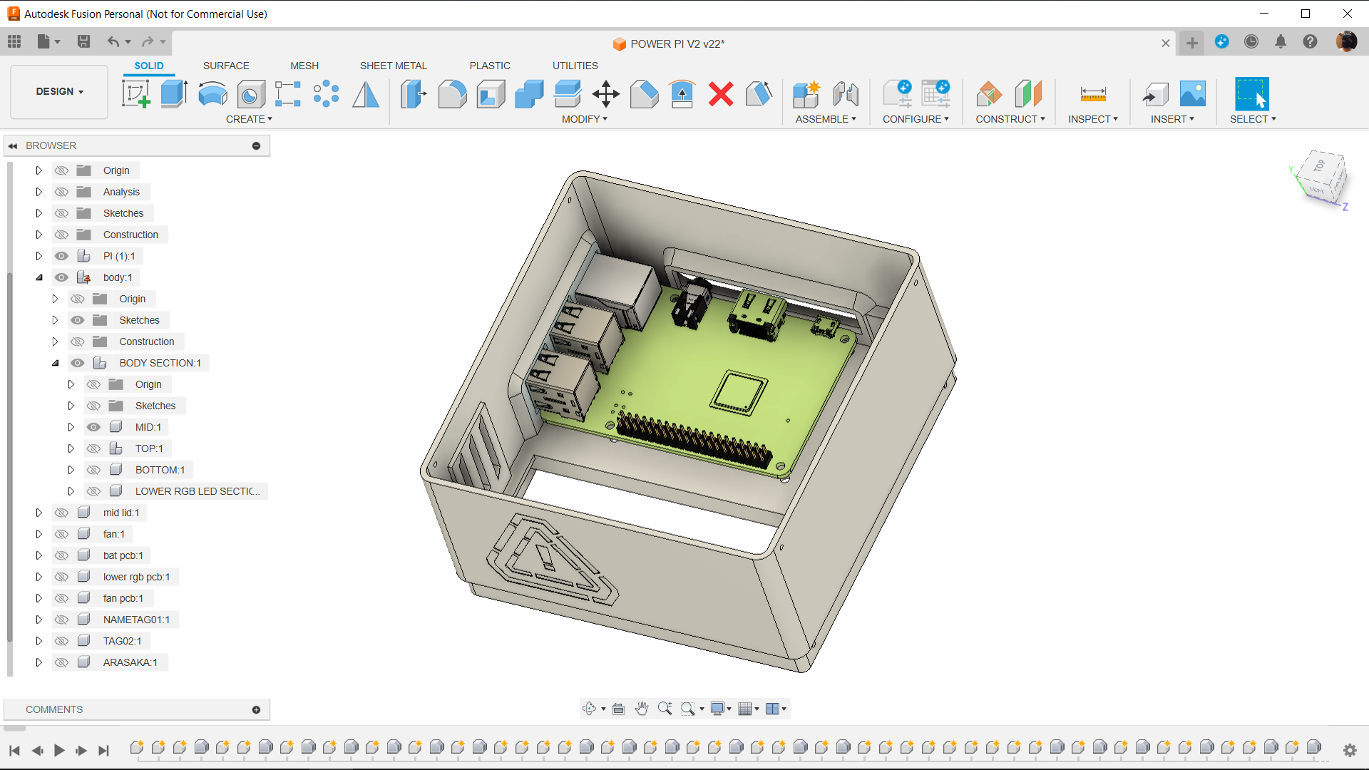
Pi Holder:
The pi holder is the section where we place the raspberry pi.
Because the Pi Holder is open on two sides, users may access all of the Raspberry Pi's I/O ports, including the power, HDMI, and USB ports on one side and all of the Ethernet and USB ports on the other.
In order to hold the Pi's position, we added four screw bosses that elevate the Raspberry Pi a few millimeters off the bottom face, creating a space between the Pi Holder's inside face and the Raspberry Pi's back.
Middle Section:
Between the Pi Holder section and the Battery Holder section, the middle section serves as a separating layer. This component essentially attaches the battery holder and Pi holder together.
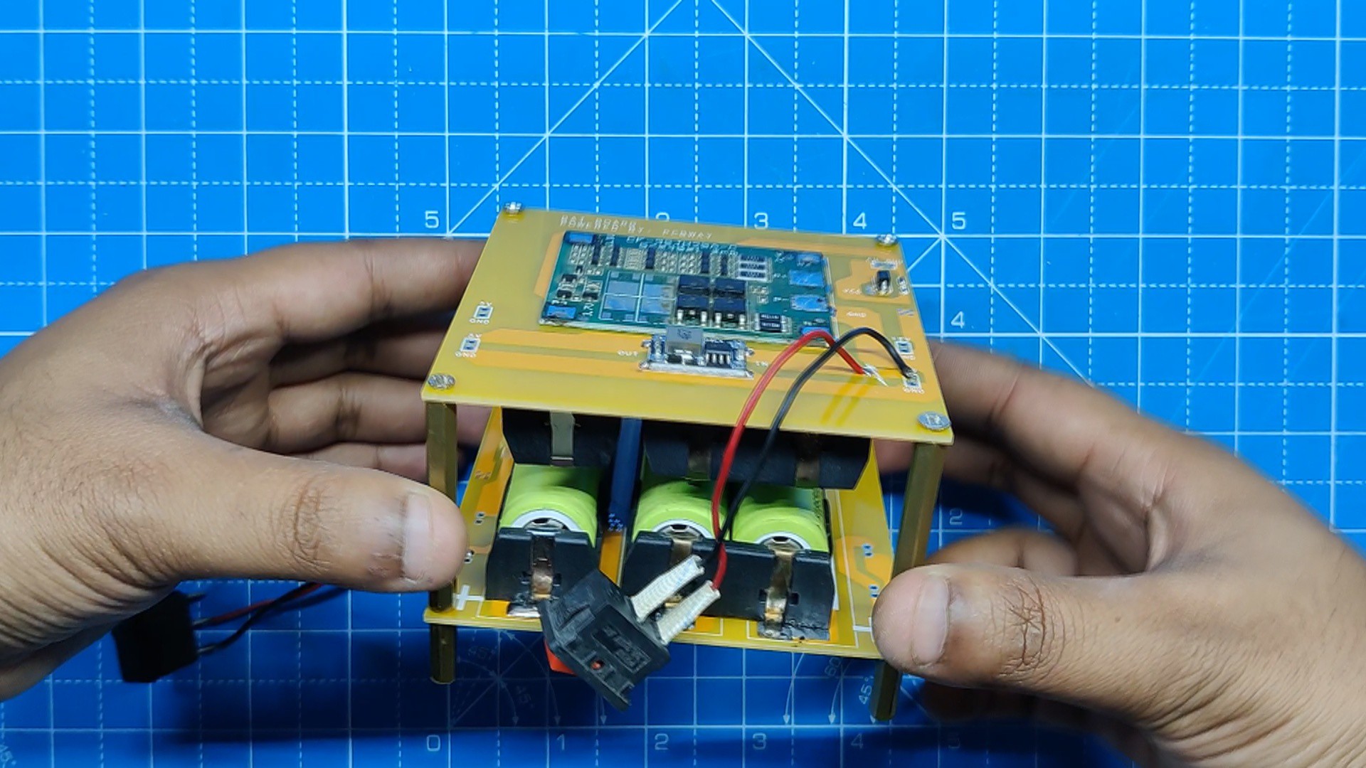
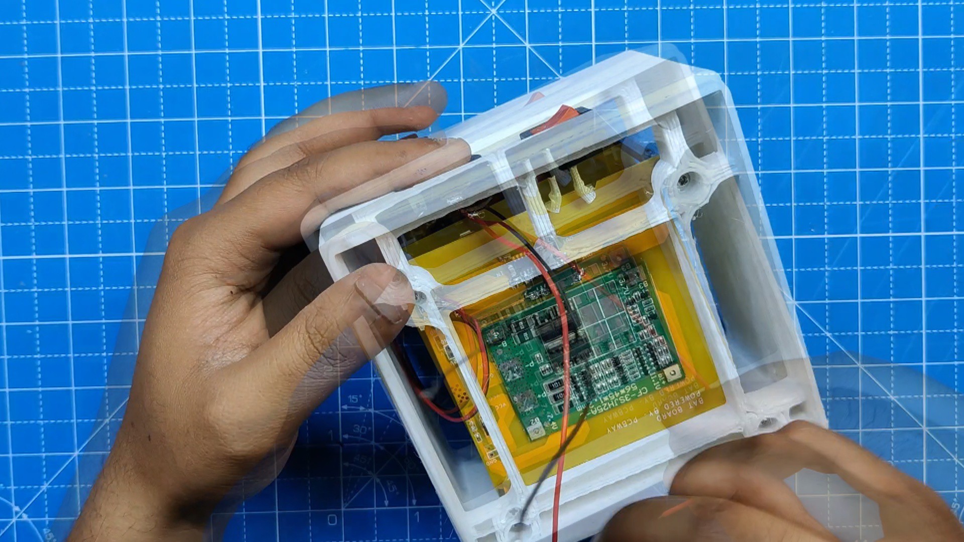
Battery Holder Section:
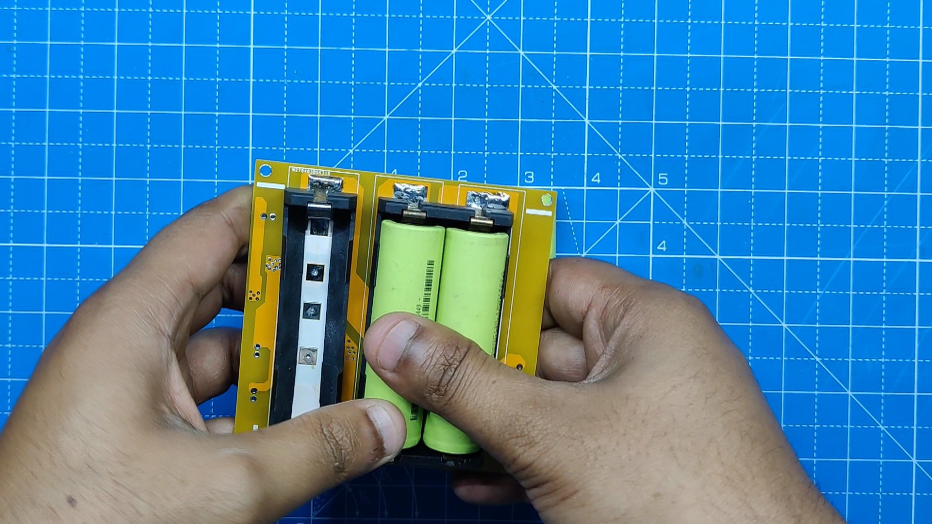
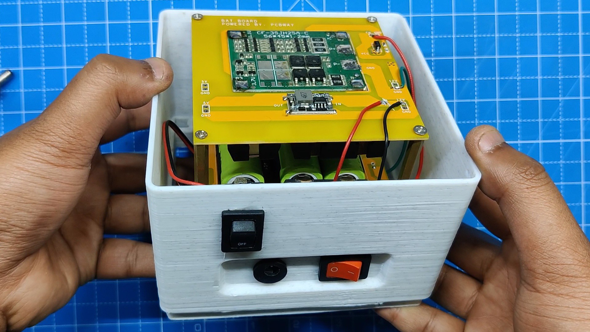
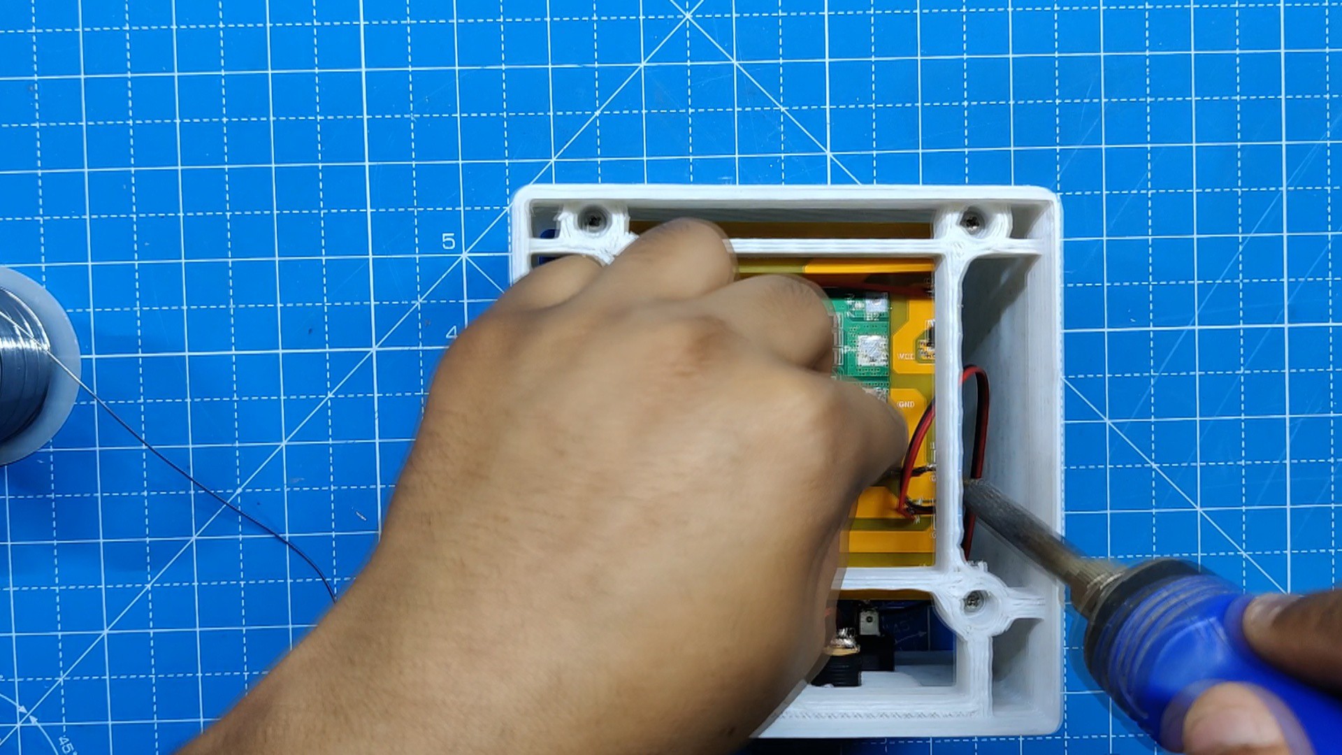
One main function of the battery holder portion is to mount the battery pack PCB in the correct position.
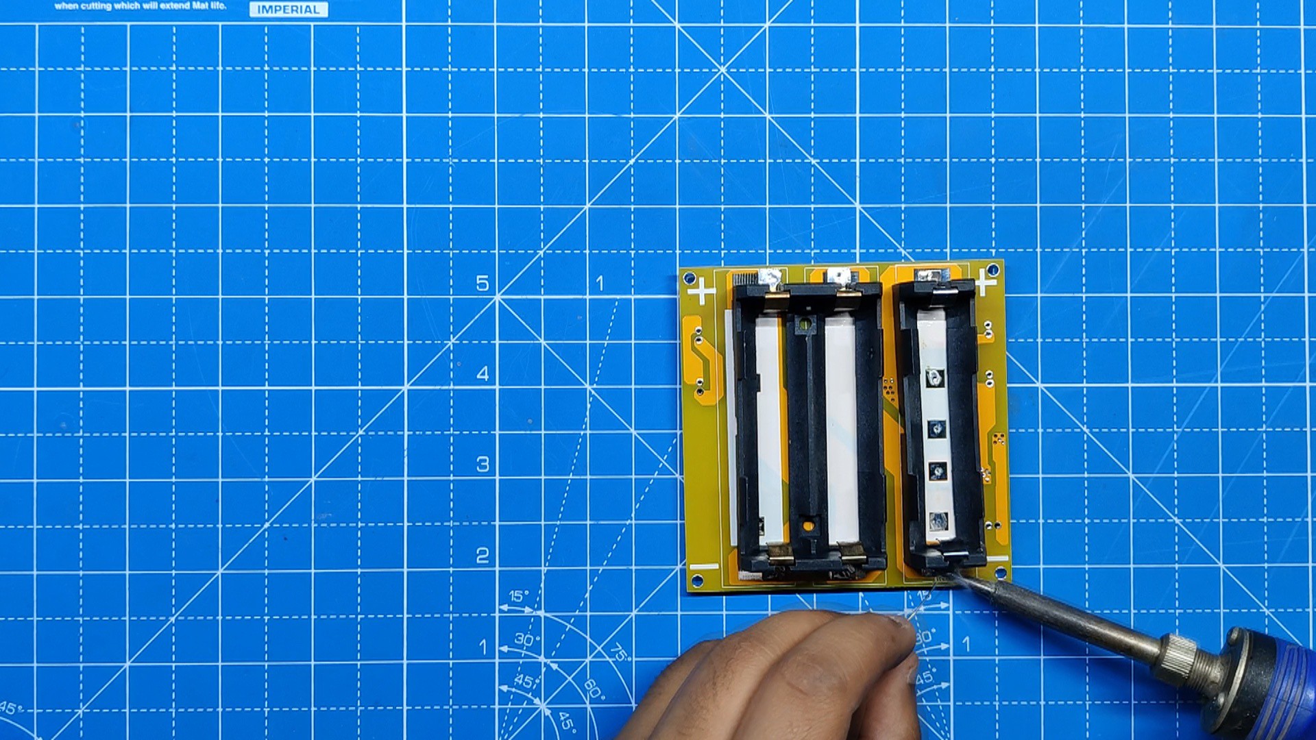
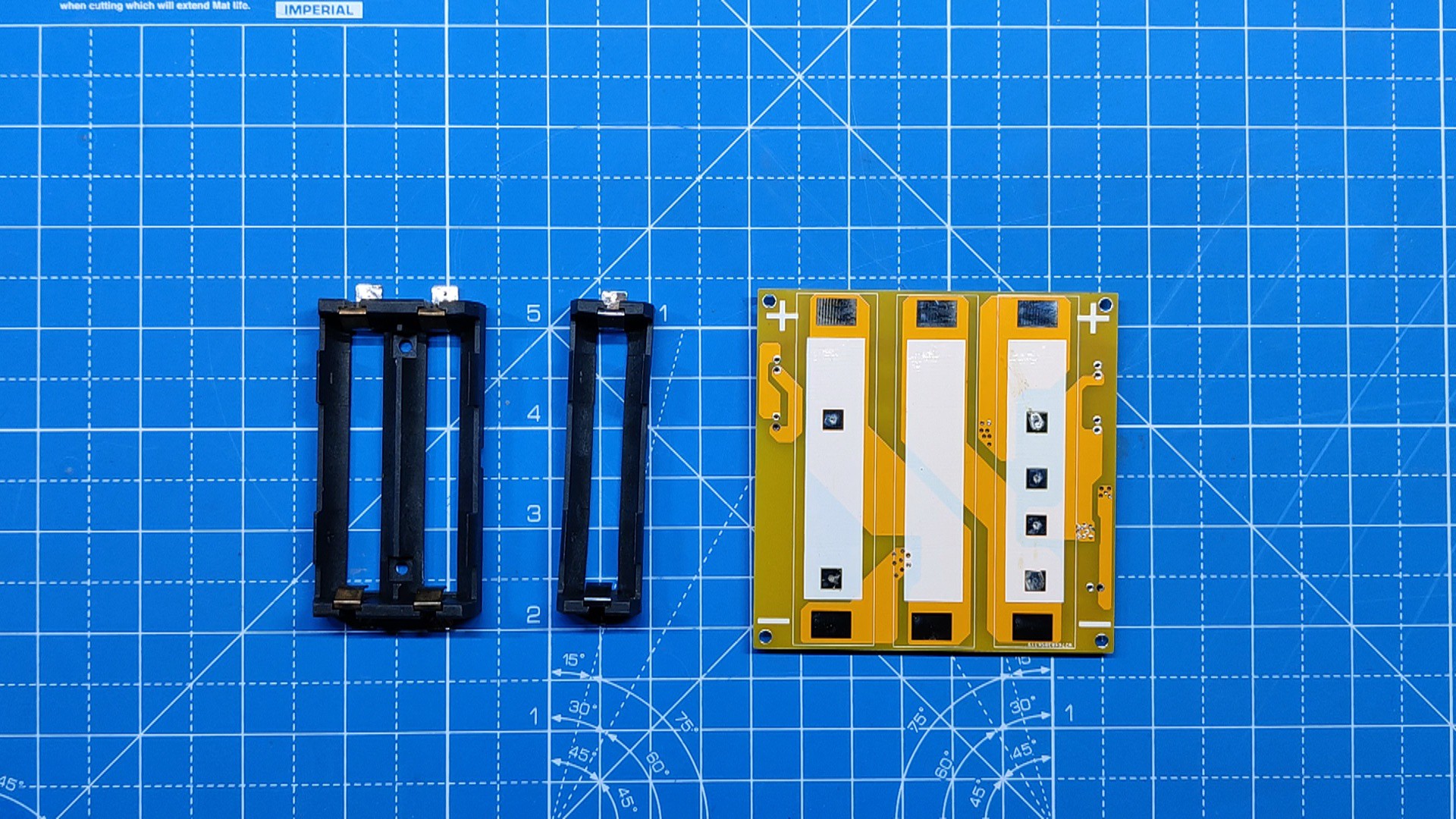
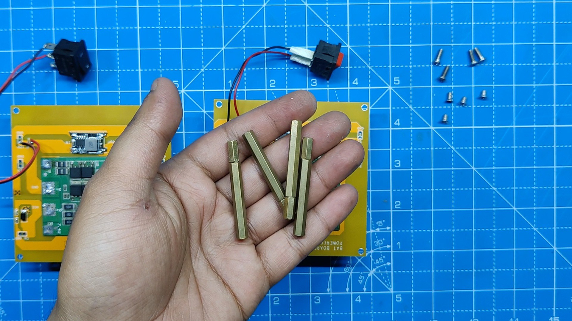
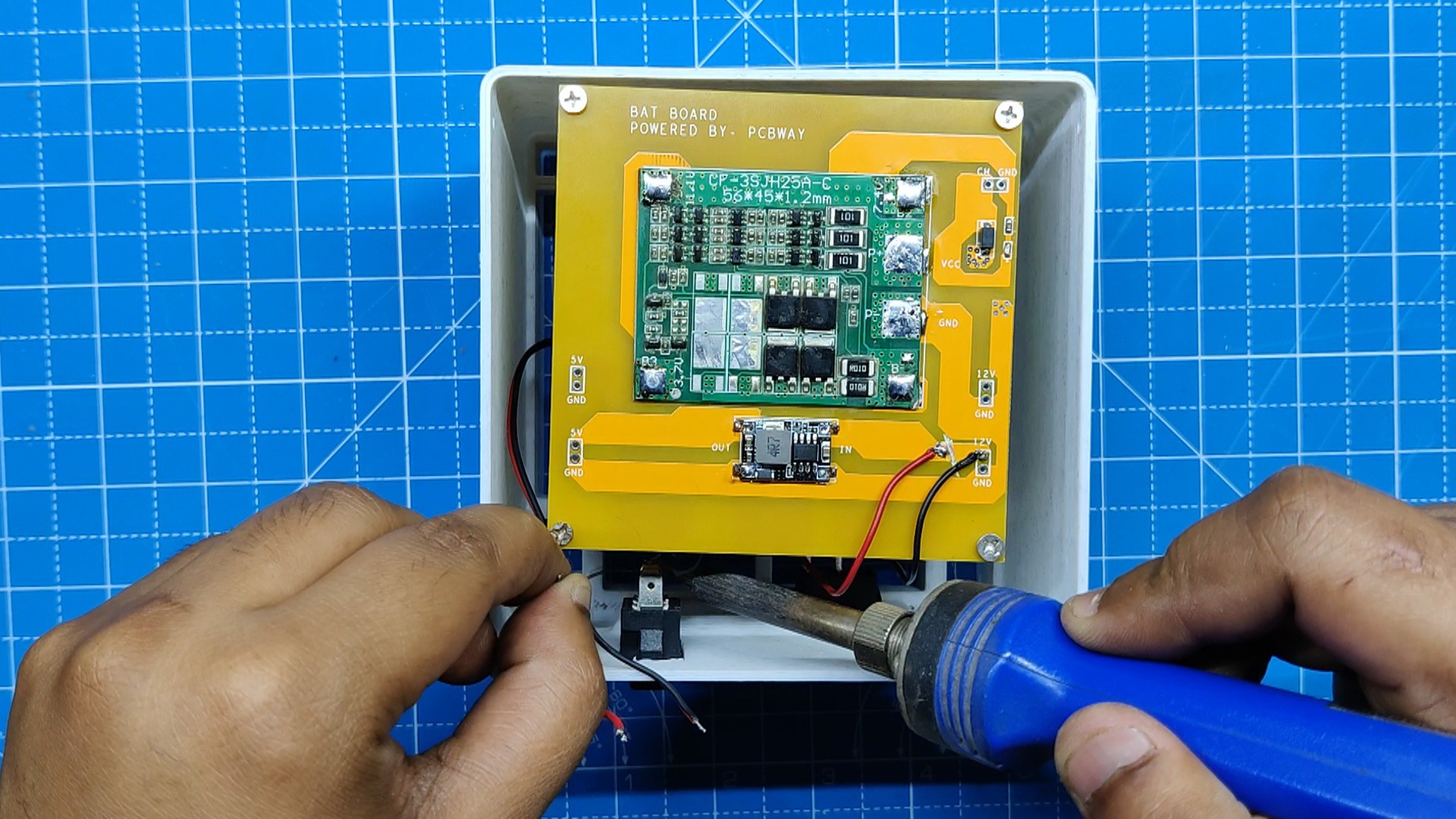
We have modeled. a PCB with an SMD lithium cell holder; this is a PCB-based battery pack.
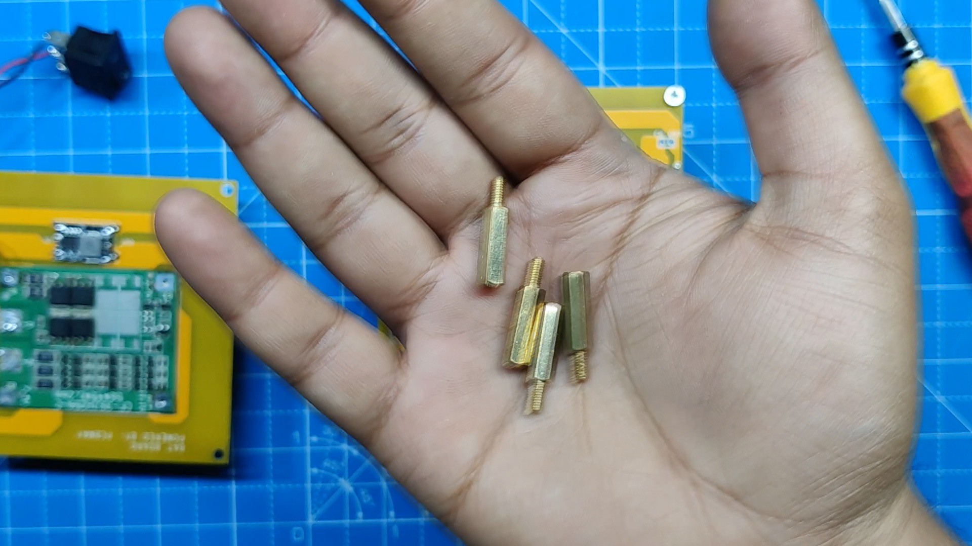
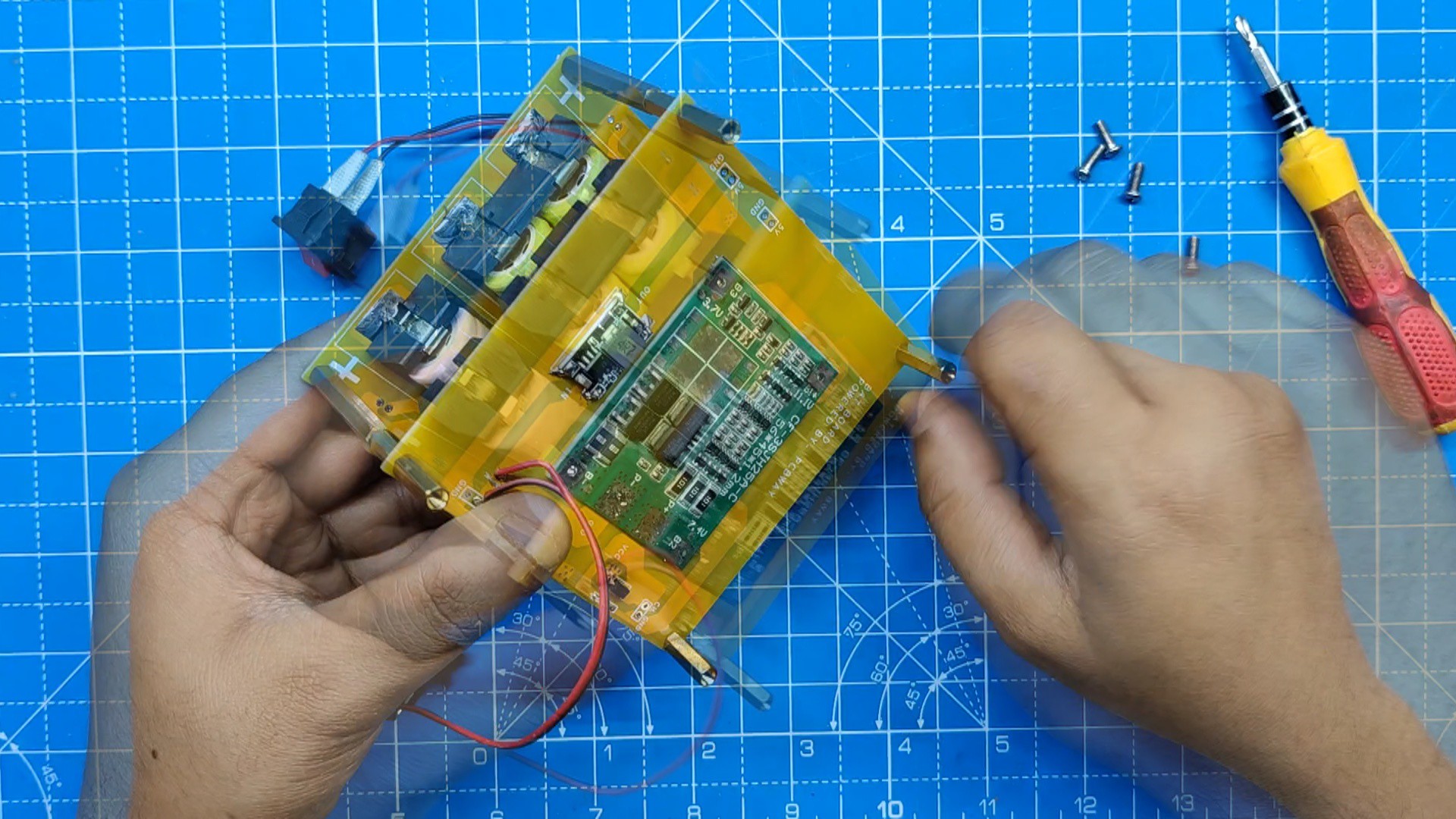
PCB standoffs are used to stack two PCBs on top of one another in order to increase the capacity of the battery pack.
We additionally mount both PCBs with the battery holder part using these standoffs.
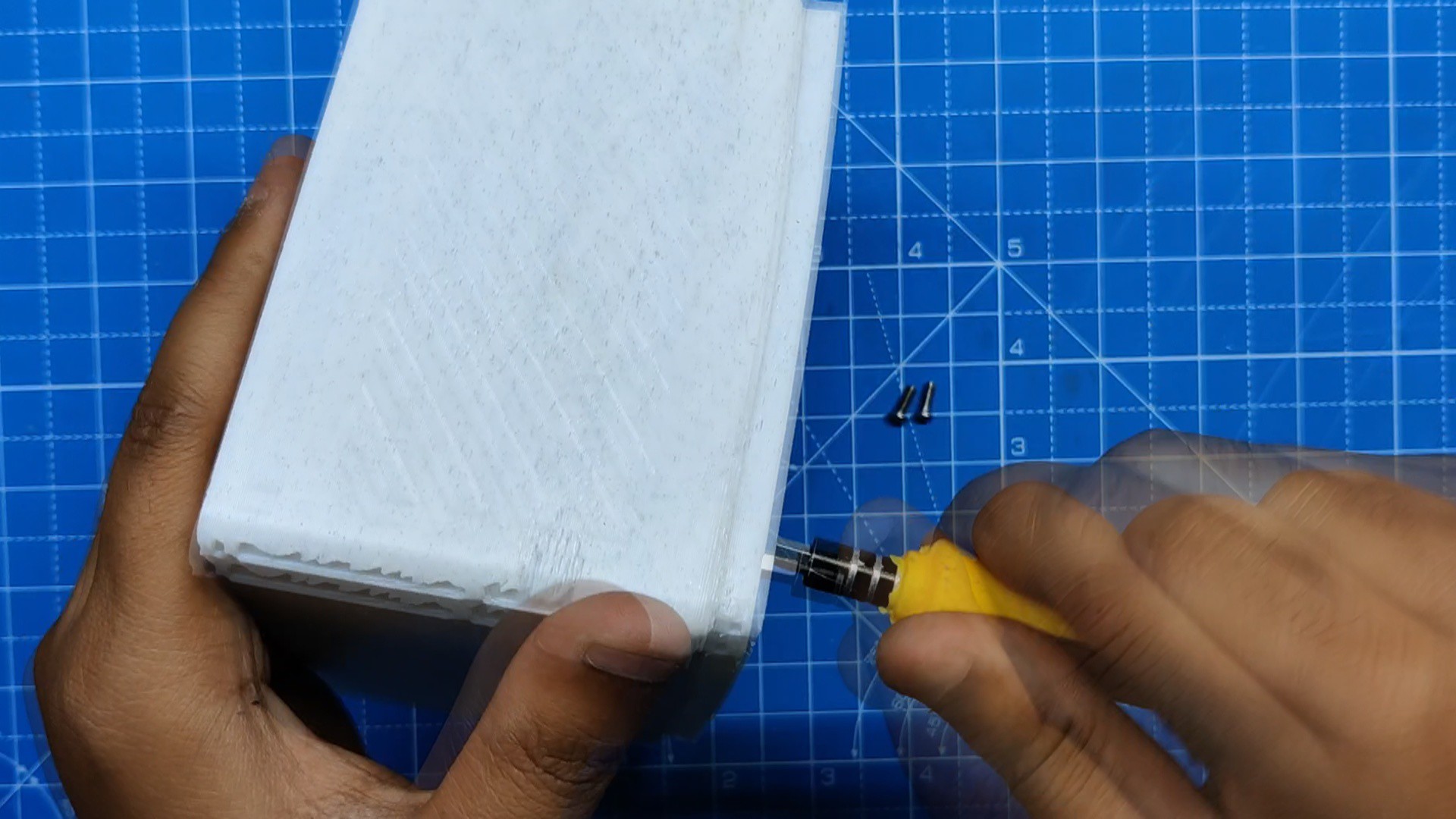
We have slots on one side for adding switches and a DC jack for charging. The switches will be used to turn the Raspberry Pi and LED board on and off.
RGB LED Holder/Base:
This model's base part, the RGB LED holder or base, serves as the solid foundation for the entire structure.
Our design now has an RGB element and a gamer-like appearance thanks to the addition of an RGB circuit inside that lights up the entire base.
The RGB LED Holder/Base will be printed with transparent PLA to diffuse the RGB LEDs placed inside.
The following sets comprised the overall structure of the design.
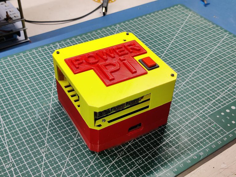
We used three different PLA colors for each part: marble PLA for the Pi Holder and battery holder, orange PLA for the center area, and transparent PLA for the top section and base.
Furthermore, we have included a few nametags and logos with a cyberpunk theme.
By stopping the print in the middle and switching out the filament for a different color, we were able to print the nametags and logos utilizing double PLA color. We had to do this since we were using Ender 3, but if you are using a multicolor printer, you can bypass this setup completely.
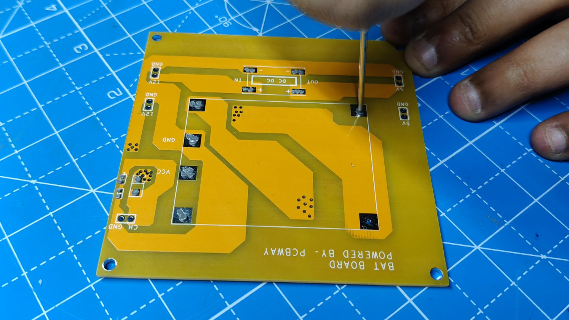
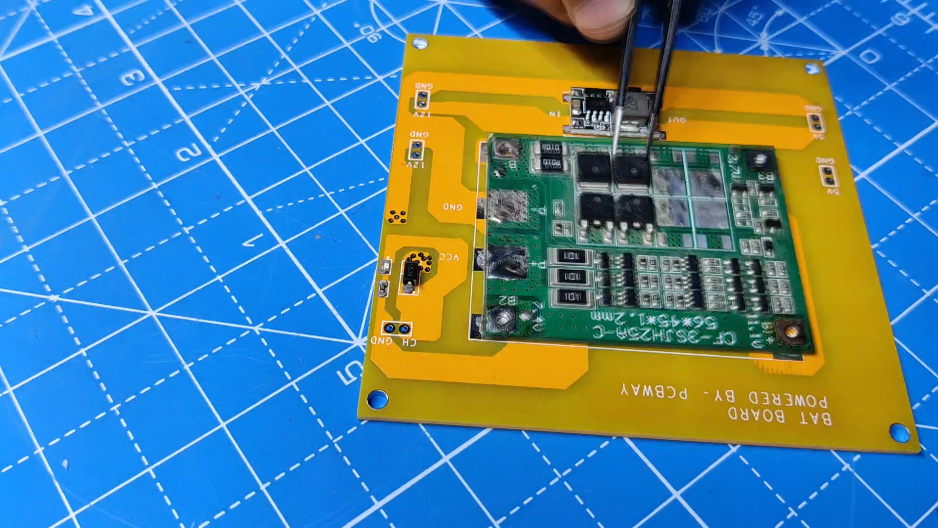
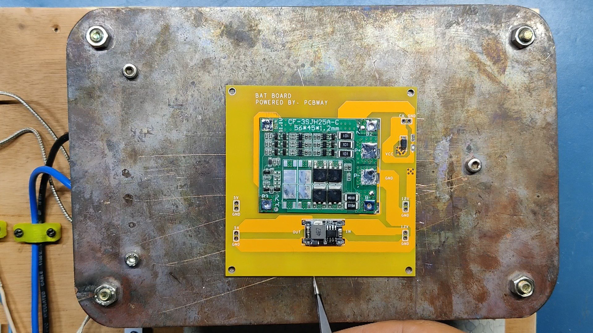
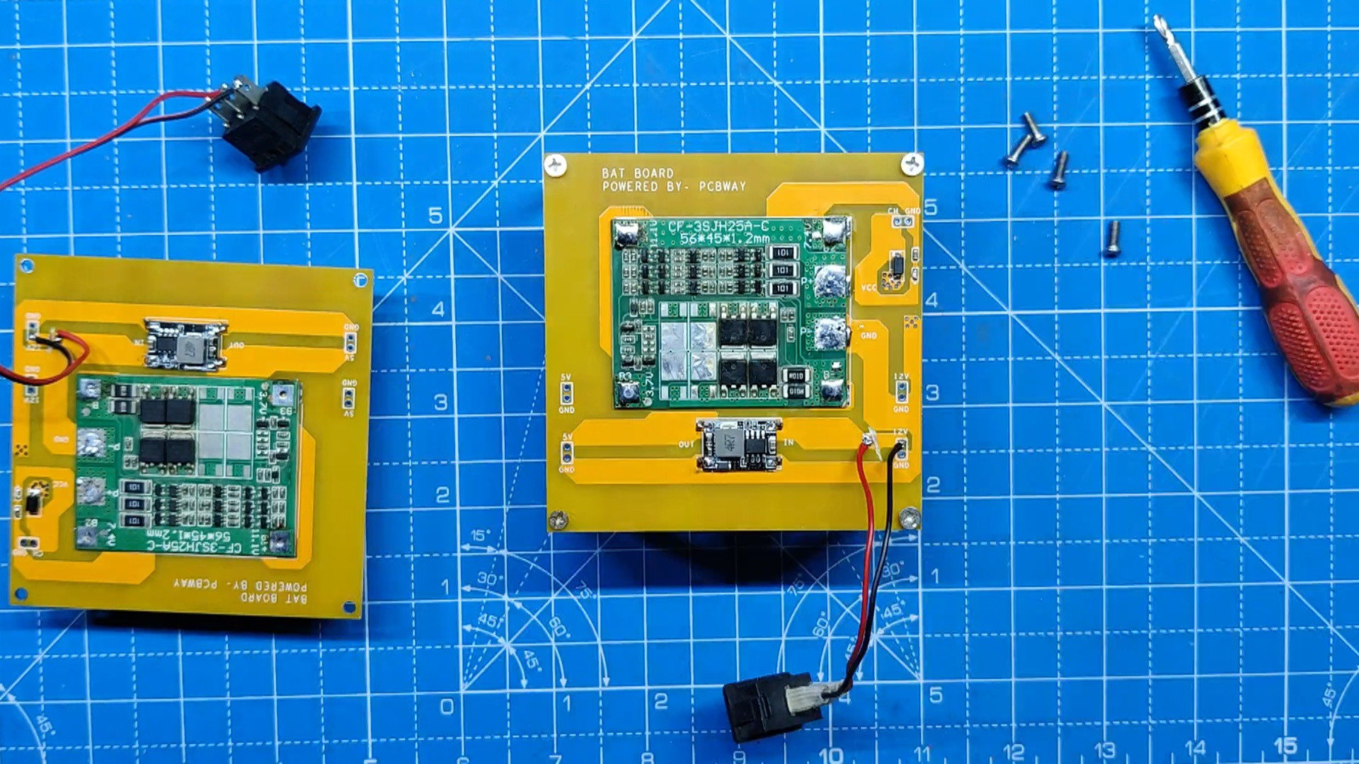
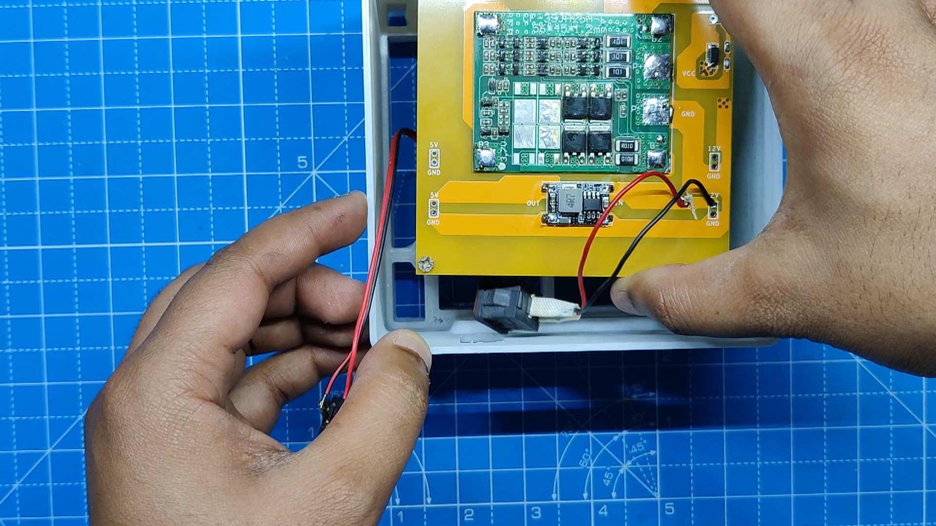
Battery Board

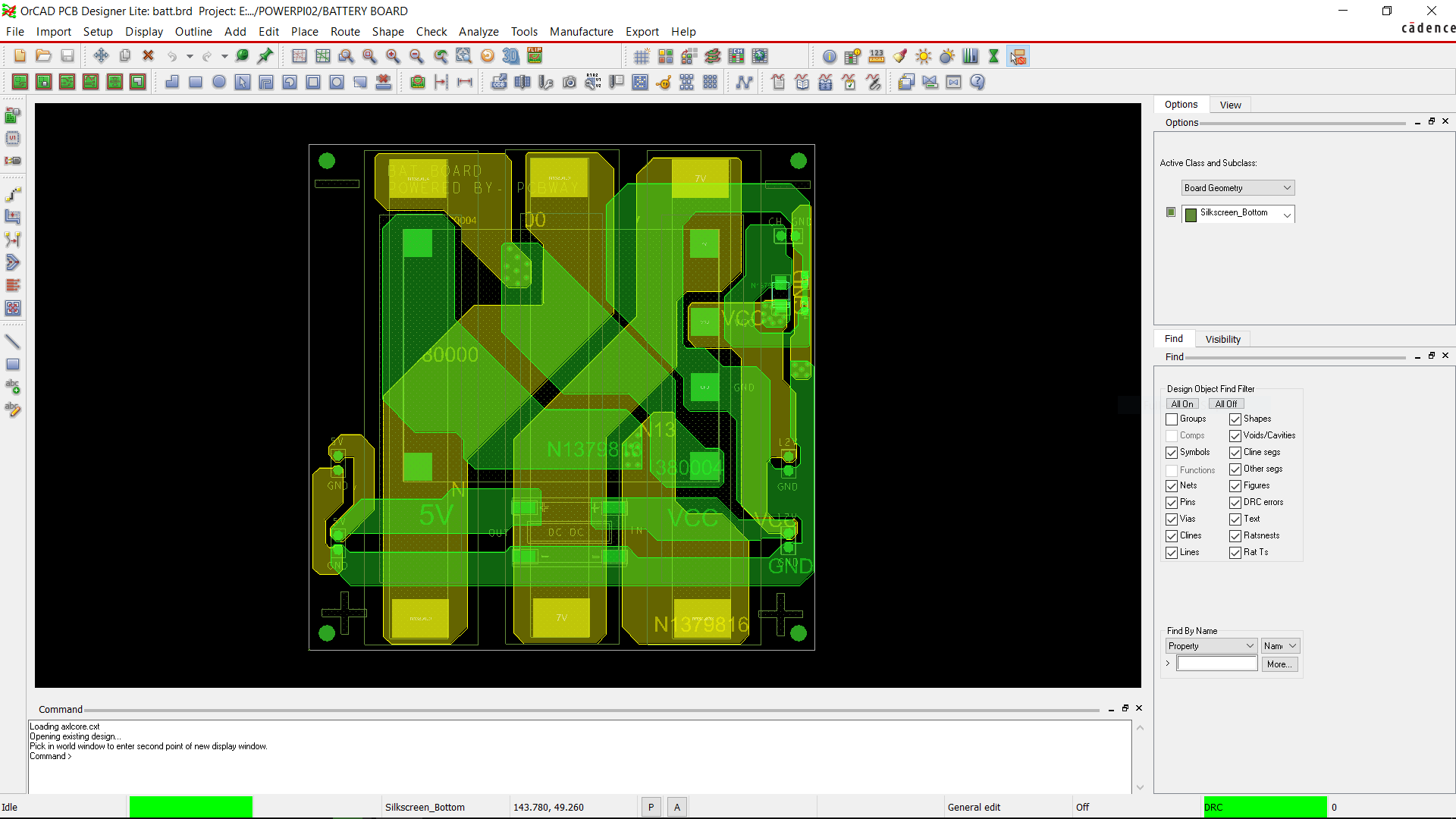
The BMS and the DC Buck Module were the project's two primary components; therefore, we began the electronics design process by creating a schematic for...
Read more »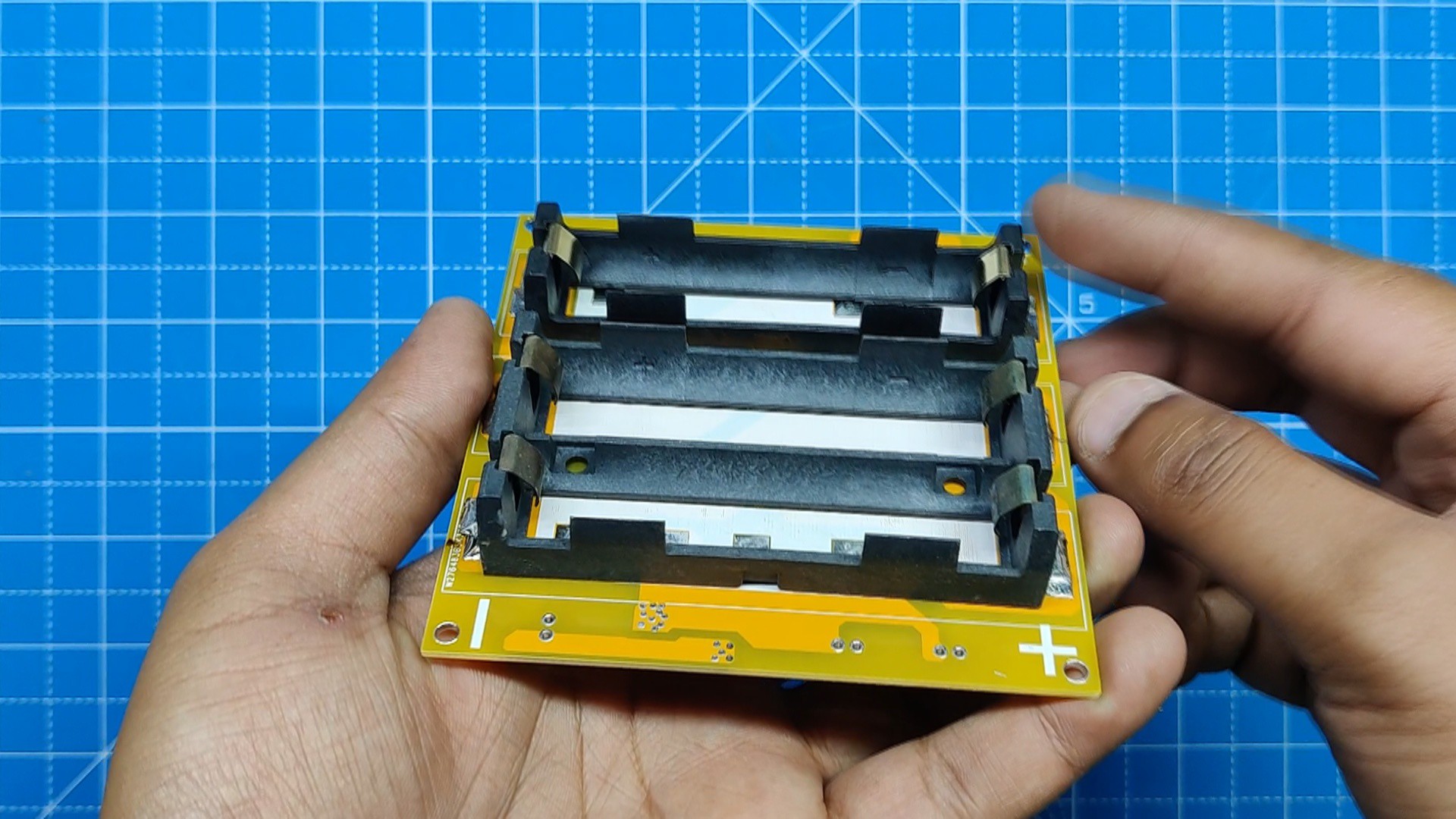
 Duane Benson
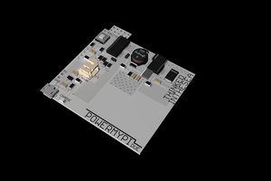
 thinkedinthesea
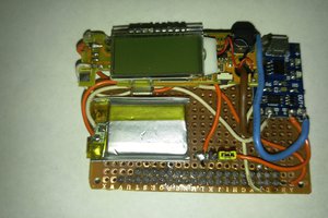

 Sean Hodgins
As for me, the customer service at King Billy Casino in Australia is outstanding. Anytime I have a question or need assistance, the support team is quick to respond and very helpful. The game selection is also impressive, with plenty of variety to keep things interesting. The fast and secure payment options make depositing and withdrawing my winnings hassle-free, which is also a big plus.