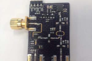
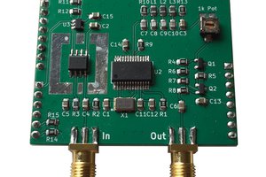
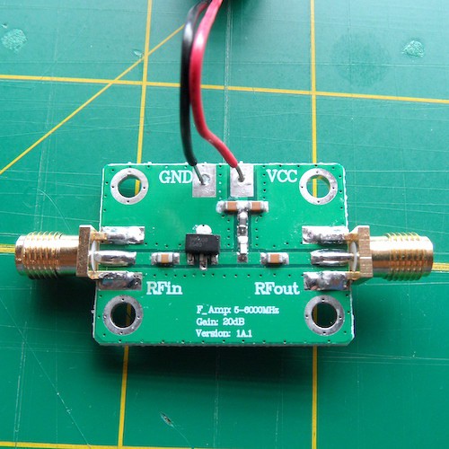
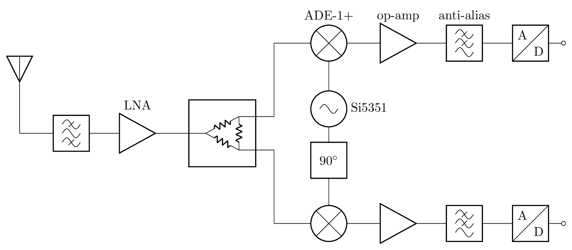
• A First Look at the Si5351 Clock Generator

    Paul Horsfall5 days ago 0 comments

    I'm considering using the Si5351 as the quadrature oscillator in my receiver. I've read a lot about this part, but I'm still unsure how it will perform in practice, so I bought a breakout board to experiment with.

    In order to make experimentation easy, I'm using a set-up that allows me to configure the part using Python code running on my laptop. In particular, I'm running Adafruit's Blinka and their Si5351 library on my laptop, and using a Raspberry Pi Pico running the u2if firmware to interface between the laptop and the Si5351.

    Here's some code I ran as an initial test. It sets up two 100 MHz outputs that are 90 degrees out of phase:

    import board
    import busio
    import adafruit_si5351
    
    # Set the following environment variable when using the Pico:
    # export BLINKA_U2IF=1
    
    i2c = busio.I2C(board.SCL, board.SDA)
    si5351 = adafruit_si5351.SI5351(i2c)
    
    # 25 MHz (crystal) * 24 = 600 MHz
    si5351.pll_a.configure_integer(24)
    
    # 600 MHz / 6 = 100 MHz
    si5351.clock_0.configure_integer(si5351.pll_a, 6)
    si5351.clock_2.configure_integer(si5351.pll_a, 6)
    
    # 90 degree phase offset for output 0
    si5351._write_u8(165, 6)
    si5351.reset_plls()
    
    si5351.outputs_enabled = True
    

    And here's what that looks like on the scope:

    One key thing I'd like to understand is whether this part can provide the 7 dBm of power required to drive the ADE-1 mixer I plan to use. My understanding is that this figure indicates the power that the LO ought to deliver to a 50 ohm load. To measure this, I connected the breakout board to the 50 ohm input of my scope (AC coupled), and used the FFT to determine the amplitude of the oscillator's fundamental frequency, from which I calculated the power.  The output drive strength of the part can be adjusted between 4 levels (called 2, 4, 6, and 8 mA) so I repeated the measurement for each level. Here are the results:

    Drive Strength (mA)
    Amplitude (dBV RMS)
    Power (dBm)
    2-10.42.6
    4-6.07.0
    6-3.49.6
    8-1.411.6

    If this is correct then it seems the part can at least deliver sufficient power. In truth, I'm not at all confident I'm doing the right thing here, but this is sufficiently promising that I'm happy to proceed.

    However, one thing I know I don't understand is the choice of names given to the different drive strength levels, since I can't see how these currents correspond to e.g. the amplitude of the outputs as measured on the scope. Please leave a comment if you can help me with this!

  • Improved LNA S21 Measurement

    Paul Horsfall6 days ago 0 comments

    I think I've figured out what caused the step in S21 that I mentioned in my previous log.

    The LiteVNA uses two different oscillators to drive the DUT, called LO and HI, with LO being used below 100 MHz and HI above. It turns out the drive strengths of these two oscillators is slightly different. This alone isn't an issue, but it also turns out that the default drive strength is such that the LNA output is driven pretty hard in my set-up. I suspect this puts the LNA in a (non-linear) region where gain depends on drive strength, hence the step in S21.

    Happily the drive strength can be adjusted, and if I reduce the drive for both LO and HI (to minimum) then the step in S21 disappears:

  • Measuring a TQP3M9009 LNA Module

    Paul Horsfall06/27/2024 at 14:33 0 comments

    I bought a PCB carrying a TQP3M9009 LNA with a view to using this as the initial gain stage of my receiver. This cost me about £8 from eBay.

    I figured the first thing to do with this was to make some basic measurements using my LiteVNA. To avoid having the output power of the amplifier damage the VNA I performed calibration and all measurements with a 20 dB attenuator on port 2. For posterity, I note that I powered the PCB directly from a 5V USB charger.

    Here's a plot showing S21 and S11:

    This seems about right to me — the measured gain is pretty similar to the gain reported in the part's datasheet. Here's a similar plot focused on the broadcast FM band:

    This shows an obvious step in gain of around 1.7 dB at 100 MHz. I don't see a similar step in the S-parameters in the datasheet, so I don't think this is expected. (I wonder what causes it? Update: I think I've figured it out. See this log for details.)

    That aside, it looks like this gives me 23-25 dB of gain across the whole band, with an input that's kinda matched to 50 ohms. So this might be good enough for some initial testing, though I do wonder if the step in gain in the middle of the broadcast FM band might cause problems later.

  • How Much Gain?

    Paul Horsfall06/26/2024 at 18:43 0 comments

    One outstanding design question is "how much gain does the receiver need?" In order to figure that out, it will be useful to know how much signal a broadcast FM signal might generate at the antenna. I figured I could estimate that by sticking an "antenna" (random wire) on my scope, setting the input to 50 ohms, and looking at the FFT of the broadcast FM band. So I did that, and here's what I saw:

    The peaks here correspond to stations that the FM radio on my phone finds, so I'm confident I'm looking at signal.

    The strongest signals have a magnitude of around -70 dBV RMS and weaker signals more like -90 dBV RMS.

    I'll need to see something like 0 dBV RMS (about 2.8V peak to peak) at the ADC, meaning I'll need around 70-90 dB of gain.

    While this is a crude estimate, it at least gives me a general sense of what I need to aim for, which is good enough for now.

  • Overview

    Paul Horsfall06/23/2024 at 15:41 0 comments

    In this project I'm attempting to build a homebrew SDR receiver. My initial goal is to be able to receive broadcast FM. I expect the result to be a janky prototype, rather than a polished product.

    The high-level hardware design will follow the phasing direct conversion approach:

    I have ideas about a few of the details (e.g. I plan to use a Si5351 for the oscillator), but much remains to be worked out. My general approach will be to build and test the individual stages in isolation to help refine the design.

    I'm currently imagining that I'll stream the sampled I/Q to a PC and do the DSP there. I'd like to write the DSP code mostly from scratch, even if it's crude, but we'll see what happens...