 Nicolas Perozzi
Introduction:
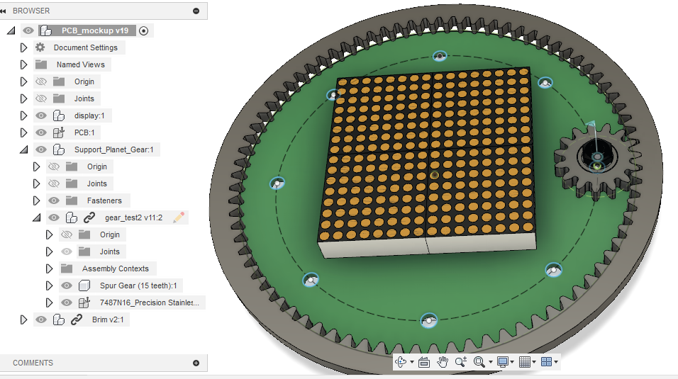
Our kitchen timer will be an iteration of mkdxdx project "REST: Kitchen timerREST: Kitchen timer". We will keep the "dail" (rotate-to-set) concept and the 16x16 led matrix but we want to do it with an ATmega328p and a custom PCB.
Among other features that we would like to add are:
- The possibility to set up several timers (in case you need to keep track of more than one pot when cooking dinner)
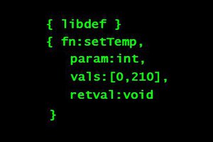
- A UART communication port that would allow us to test the device via serial commands.
Motivation:
Both Erasmus Cedernaes and I belong to Stockholm Makerspace. On the same day, we messaged each other a link to mkdxdx project. We were very excited about building something that would be "practical" so we decided to team up and work on this together. Additionally, we share an interest in working with the AVR MCUs and this project seems like a nice blend of different disciplines (programming, electrical, mechanical, 3d printing, and design), without feeling overwhelming.
Objectives:
- Create something... if it "useful", it is always a plus.
- Work on a project together
- Learn new things
 Daniel Sikar
 Ilyas Akhmetzyanov
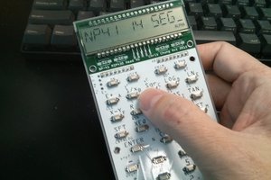
 Chris Chung
 Gabriel D'Espindula