 agp.cooper
-
Unfolded Offsets
03/05/2017 at 07:07 • 0 commentsUnfolded (Cut Out) Offsets
In order to cut out plywood pieces for your boat/canoe, the design needs to be "unfolded" from 3D to 2D. Now there are some very good programs on the Internet that can do this, my favourite is Carlson Design "Hull Designer" or "Hulls" (http://carlsondesign.com/projects/hull-designer). The only problem with this program is that the program needs to be run in compatibility mode (otherwise the behaviour is frustratingly strange).
The original canoe was unfolded using a spreadsheet (i.e. formula based). The problem is that building a design is a painfully slow process and there is not much hope of explaining its use. About three years ago I wrote a macro that reads a Table of Offsets (what you will often find in a boating books or magazines) and calculates the unfolded offsets directly. Like most home brew programs there are probably bugs that need to be fixed and improvements that can be made and no documentation.
The Offset Table
Here is a typical offset table for a canoe:
![]() (source: https://s-media-cache-ak0.pinimg.com/originals/d5/70/16/d57016a2123565eb573042f4b155c4d4.jpg)
(source: https://s-media-cache-ak0.pinimg.com/originals/d5/70/16/d57016a2123565eb573042f4b155c4d4.jpg)Although there is everything you need here (that is the above image) to physically build the canoe, it is still a tough job for a program to decode. Below is the offset table for my canoe:
![]() Other than the offset table being rotated, there are two additional fields:
Other than the offset table being rotated, there are two additional fields:- Break: If TRUE then the "line" or "chine" can have a sharp bend
- Colour: Having colours helps to identify the "plank"
Two other comments are that although each "station" or "section" above have the same "X" co-ordinate, this is not a requirement, and although I have filled in each cell, again this is not a requirement.
It helps a lot if you run the "lines" or "chines" all the way though to a common point at each end of the table.
Running the Macro
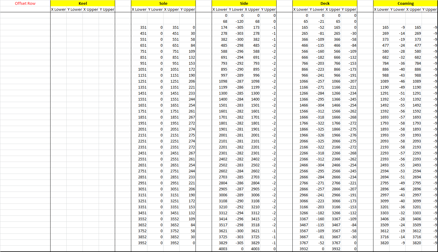
After checking that you have filled out the yellow cells, click the blue arrow. A minute later (yes it is slow so don't panic!), it will update the "Unfolded Offset Table":
![]()
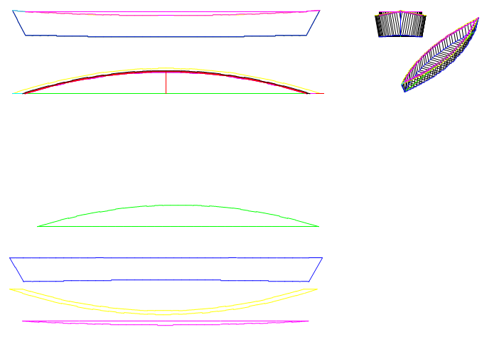
It will also update the 3D drawings:
![]() The "Unfolded Offset Table" will need to be moved around to suit the plywood, so another page allows this. The "plot" button on this page will update the unfolded drawing:
The "Unfolded Offset Table" will need to be moved around to suit the plywood, so another page allows this. The "plot" button on this page will update the unfolded drawing:![]()
AlanX
-
Basic Canoe Design
02/23/2017 at 07:52 • 0 commentsBasic Canoe Design
Before considering the pontoon and bridge design here is the basic canoe design. I have uploaded a spreadsheet with all the following calculations.
Basic Canoe Measurements
Canoe Basic Metrics Length Overall (LOA) 3.930 m Beam Overall (BOA) 0.650 m Length Water Line (LWL) 3.600 m Beam Water Line (BWL) 0.550 m Actually the bottom width Depth Water Line (DWL) 0.075 m Rocker 0.025 m Amidships Deadrise 0.000 Degrees Flat bottom Amidships Freeboard 0.200 m Forward Freeboard 0.325 m Rear Freeboard 0.325 m Note: Bold numbers are inputs.
Design Pressure
Now some basic calculations but most importantly the design pressure:
Basic Calculations Mid-Section Area 0.041 m^2 Plan Water Line Area 1.320 m^2 Displacement Volume 0.088 m^3 Displacement Weight 90.200 kg Prismatic Coefficient (cp) 0.593 Displacement Length Ratio (DLR) 42.080 Hull Speed 4.605 kt Design G Force 3.500 g Light duty Design Pressure 2.346 KN To calculate the design pressure I have assumed the canoe is loaded 3.5 time the rated displacement of 90 kg.
Bottom Plywood Thickness
Bottom Plank Design Design Pressure (P) 2.35 kPa Span (L) 550 mm BWL Allowable Stress (S) 14000 kPa F14 Plywood Plank Thickness (t) 5.03 mm t^2=P*L^2/2/S, ~fixed sides Design Plank Thickness (t) 6.00 mm Modulus of Elasticity (E) 8400000 kPa Factored 80% for wet condition Moment of Inertia (I) 18000 mm^4 Deflection (d) 3.70 mm d=P*L^4/384EI (2% max) Deflection Ratio 148.74 Maximum Concentrated Load 0.50 kN =S*t*t Here I calculate 5 mm but the nearest larger plywood thickness is 6 mm. Although this is okay for water pressure it is too thin for an adult to stand on. The middle section of the bottom of the canoe needs to be reinforced.
Bottom Reinforcement
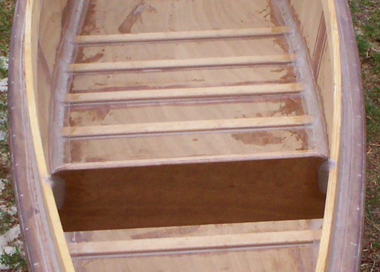
Upon reflection it would have been easier just to double up the plywood in the middle of the canoe or that fibre-glass both sides with 4 oz/sq_yd fibre-glass cloth. The calculations assume a "T" section across the hull (beam-ward) with plywood strips (see image). It is also assumed that two "T" sections share the load as they are quite close together:
Hull Centre Reinforcement T-Section Modulus Maximum Rib Spacing (Flange Width) 256 mm Fw<36t+w Design Rib Spacing 150 mm Plank Thickness (Flange Thickness) 6 mm Rib Thickness (Web Height) 6 mm Rib Width (Web Thickness) 40 mm A 1776 mm^2 cy 3.8 mm From top of T cx 0.0 mm From centre line of T Ixx 10474 mm^4 Iyy 8420608 mm^4 Design Point Load 1.00 kN ~100kg Span 550 mm Allowable Stress 14000 kPa F14 Plywood Bending Moment 69 Nm Section Modulus 2749 mm^3 Working Stress (per rib) 25013 kN Distribute Load (over two ribs) 12506 kN Safety Factor 112% Here is an image of the reinforcement:
![]()
If you look carefully you can see the filled wire holes below the single strip of 4 oz/sq_yd fibre-glass tape.
Side Plank Calculations
If the side plank is the same thickness as the bottom plank then no calculations are necessary but here they are anyway:
Side Plank Design Design Pressure (P) 2.35 kPa Span (L) 275 mm Allowable Stress (S) 14000 kPa F14 Plywood Plank Thickness (t) 2.5 mm t^2=P*L^2/2/S, ~fixed sides Design Plank Thickness (t) 6.0 mm Okay Hog and Sag Calculations
So put 3.5 big guys in the canoe and get two even bigger guys to lift the canoe up by the ends. Is it strong enough (not actually required)?
First the Load Calculation:
Hull Section Modulus Triangular Load & Free Ends Design Pressure 2.35 kPa Width 550 mm BWL Length 3600 mm LWL Allowable Stress 14000 kPa F14 Plywood Required Section Modulus 99547 mm^3 SM=PsL^2/12/S Now the Strength Calculation (assuming a channel section):
Channel Model Chine Width (web) 550 mm BWL Side Height (flange) 275 mm Deck Width (lip) 50 mm Thickness (t) 6 mm cy (from bottom) 86 mm I 75400372 mm^4 Rg 102 mm Radius of gyration Slenderness Ratio 35 Z 398812 mm^3 Safety Factor 401% Assumes no significant keel or stringers Yes, a 401% safety factor is okay.
Fibre-Glass Tap Join
You will be lucky to find anything on the Internet calculating the fibre-glass joint strength other than rules of thumb. Here are some actual calculations:
Plywood Fibre Glass Joins Spw 14000 Pa b 1 m h 6.00 mm M 84000 Nm M=Spw*b*h^2/6 Sfg 120000000 Pa t 0.12 mm t~((6*M*h/Sfg/b+h^3)^(1/3)-h)/2 F/G Weight 1.87 oz/sq_yd Each side of plywood F/G Overlap (each side of join) 18 mm =3*h [JS = 15%*(1+L/h)] Scarf Joins
You will find rule of thumb of beween 8 to 1 all the way up to 12 to 1 for scarf joins:
![]() (source: www.amateurboatbuilding.com/articles/howto/joining_ply/scarf1.gif)
(source: www.amateurboatbuilding.com/articles/howto/joining_ply/scarf1.gif)This tells you the fibre-glass tape should span 8 times the plywood thickness:
![]()
(source: www.amateurboatbuilding.com/articles/howto/joining_ply/plyjnt5.gif)
However, I found a paper that suggests that 6 times is enough (www.wfdt.teilar.gr/research.files/2005_05.pdf).
AlanX
A Plywood Canoe
I built this canoe 10 years ago. It was fun but various design flaws has limited it use. This project is about a salvaging the canoe.
 (source:
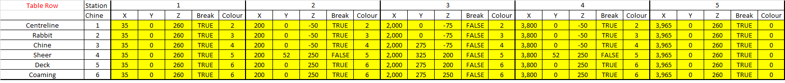
 The "Unfolded Offset Table" will need to be moved around to suit the plywood, so another page allows this. The "plot" button on this page will update the unfolded drawing:
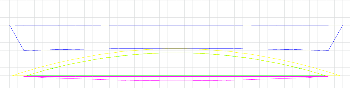
 (source: