 lukasz.iwaszkiewicz
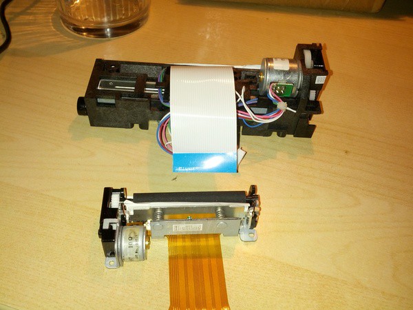
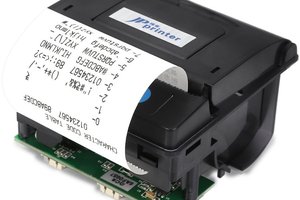
At first I bought broken receipt printer for very little money (like $7). It understood some dialect of ESC/P, but as described on the auction some of it's logic was broken in some way. It would print only one char in a row, and then hang. I described my battle here.
Then I considered whether to abandon the project, or try to use the thermal head itself thus implementing something printer-ish by myself. Without further ado I gained so much information on the topic I could, and after verification that the head is OK i finally got it to print something. This was described in more detail in my other post here :
And after this first success I started to wonder if I could do better, and If gray-scale images are possible.
What I managed to achieve is depicted somewhere on the left. These images are 4 shades (i.e. black, 2 shades of gray and white), 2 bit deep images. It turns out that thermal printers aren't so good at printing shades of grey though, so the dithering is more apparent than those shades :D Some technical details:
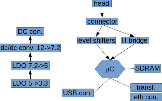
Now it is powered by Texas Instruments TM4C123, but I plan to switch to TM4C129 which has embedded ethernet phy. I plan to attach something like 8MB of RAM, and make it compatible with some popular platform like Arduino. But it could work standalone of course as a USB or network printer (compatible with some simple dot-matrix one). Another feature I was thinking of, was to embed some simple web client which would download and print some data from somewhere (like facebook, twitter or this new data.sparkfun.com maybe?)
The system design document required by 2nd stage can be found here.
The only library (or set of libraries bundled together) used for now is the TivaWare which is available partially in terms of BSD, LGPL, GPL, and TI Commercial licenses. The whole bundle is advertised as "free license, and allows royalty-free use" though. License text can be found in the TivaWare package here.
Another library that will be used is the ImageMagick distributed under the Apache 2.0 license.
Schematic as well as PCB layout will be designed in Eagle and included in the SVN linked down below (only C source is uploaded for now) under the terms of the GPL license.

 Timescale
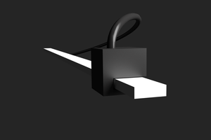
 ziggurat29