0%
0%
First Year Honors Project
My completed first year honors project at the University of Arizona
 Noah Thurston
Become a Hackaday.io member
Already have an account? Log in.
Just one more thing
To make the experience fit your profile, pick a username and tell us what interests you.
Pick an awesome username
hackaday.io/
Your profile's URL: hackaday.io/username. Max 25 alphanumeric characters.
Pick a few interests
Projects that share your interests
People that share your interests
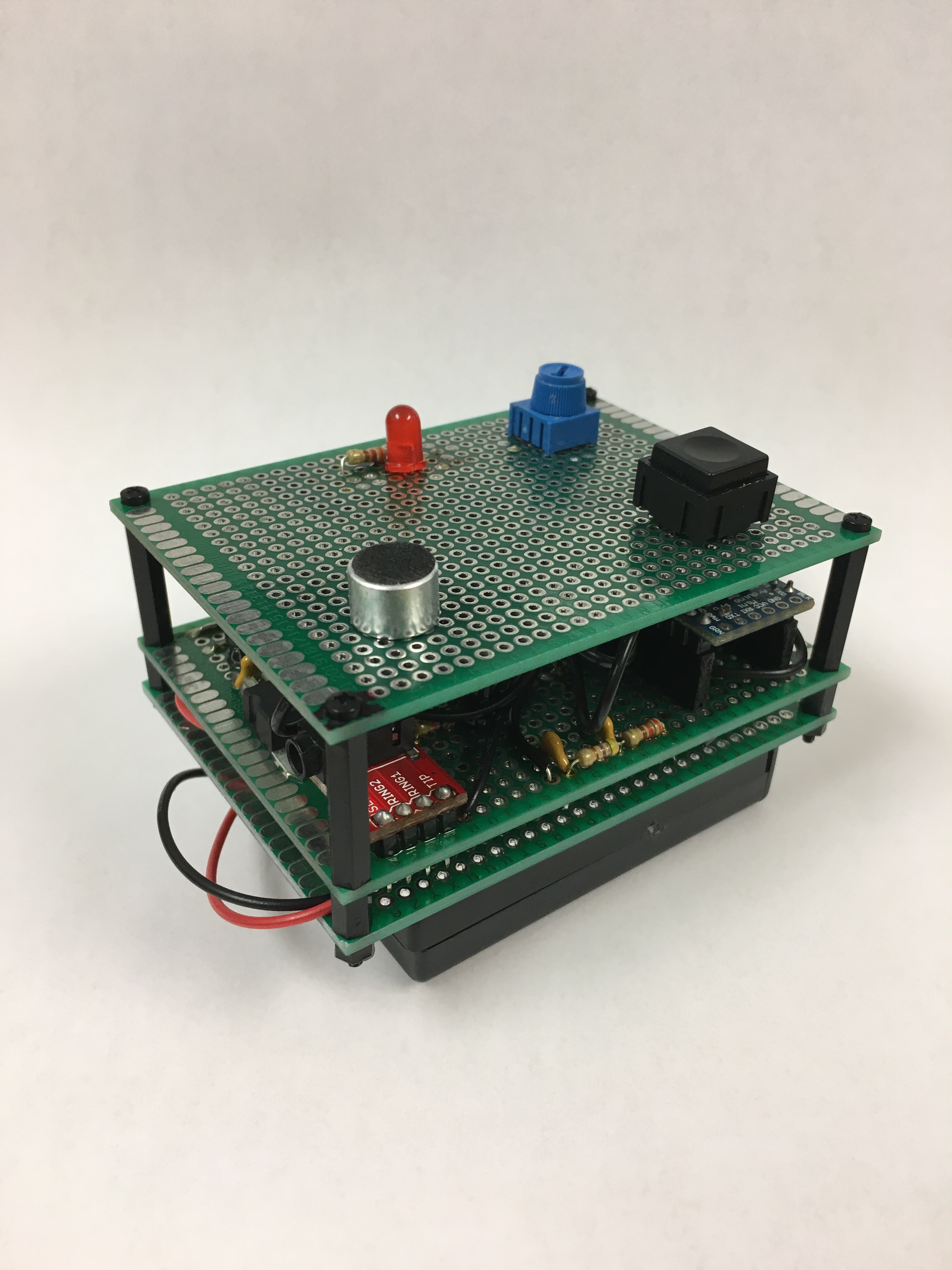
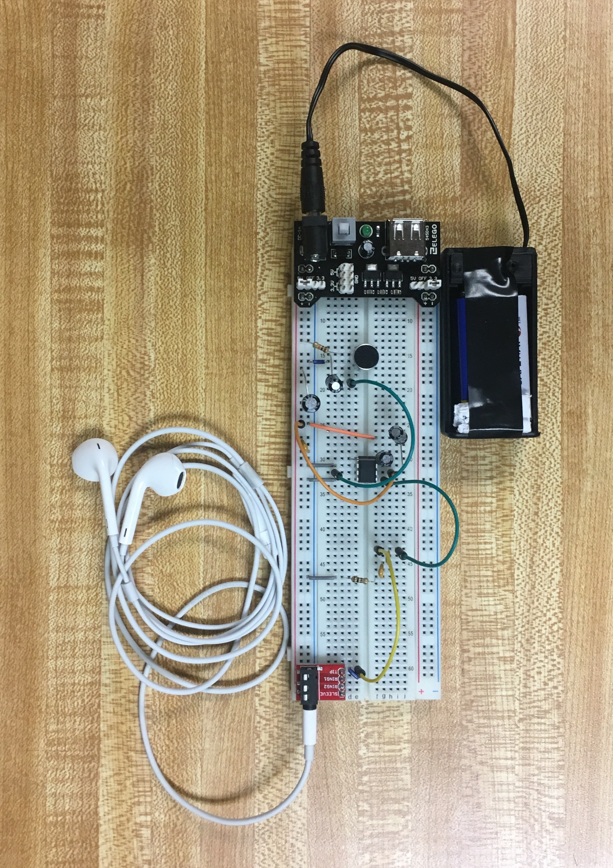
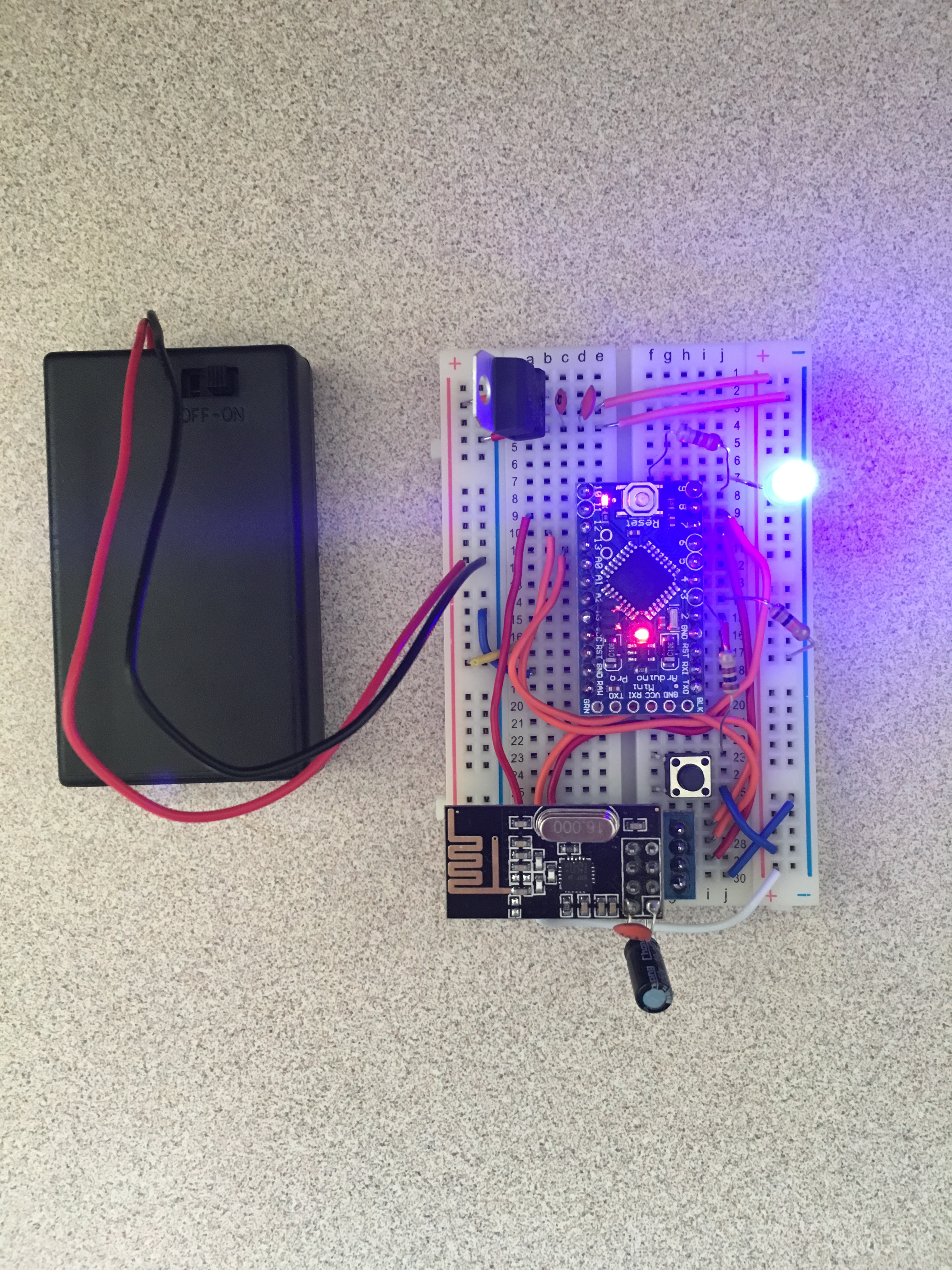
 I also soldered one radio onto a protoboard for my presentation, the pictures of which are below. The potentiometer is the volume control dial for incoming audio, the LED below it is an indicator for the incoming audio, the pushbutton is to "push-to-talk" and the electret mic below it is for picking up the audio for transmission. And the final PCB sticking out the top shows the trace antenna, and since the module is placed into a 2x4 set of female headers, any nRF24 module can be used, including one with a real antenna.
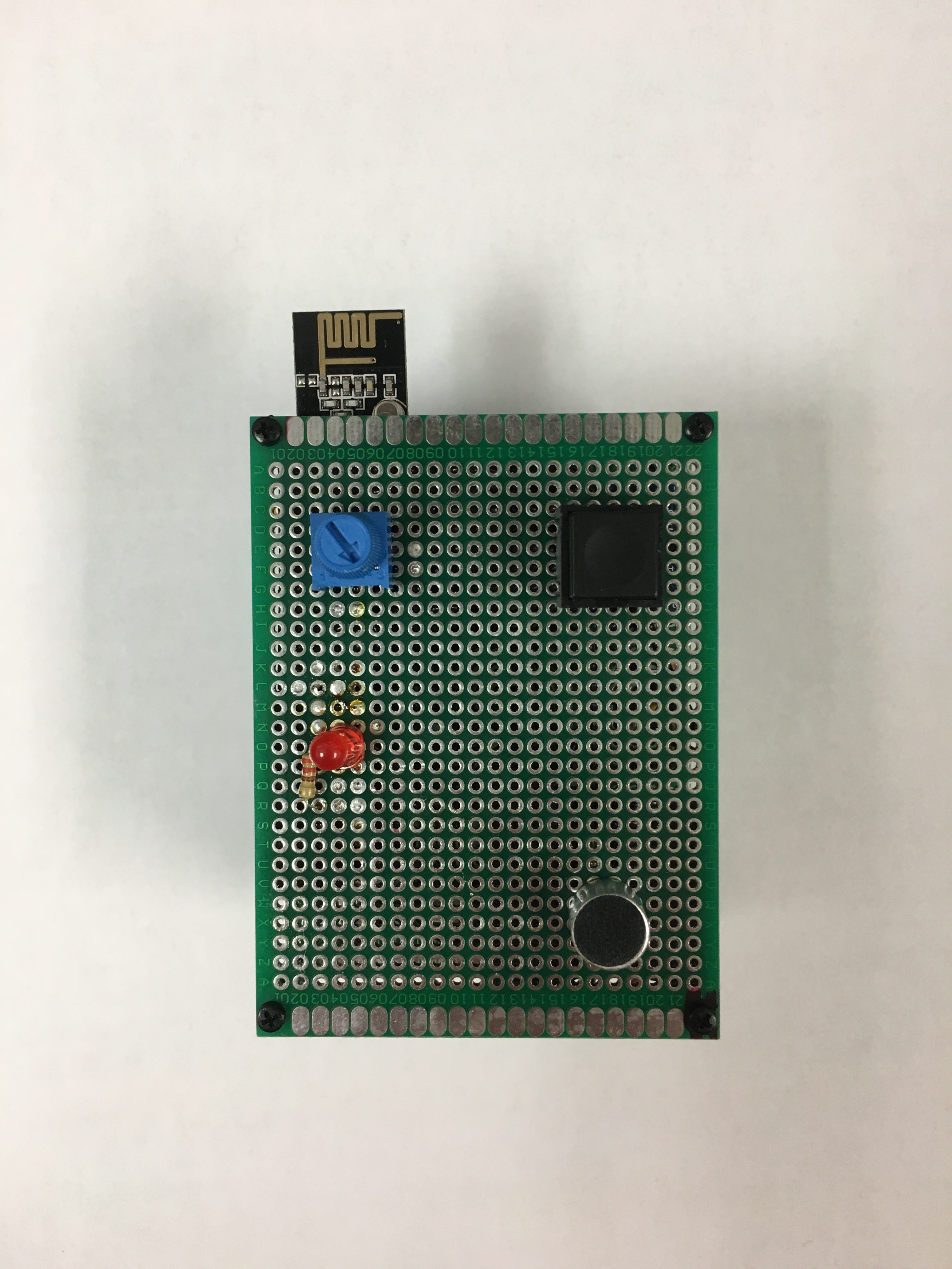

 Orlando Hoilett
 Slavko Glamocanin
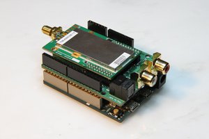
 Turbyho
 Alan Green