 Tobias Kuhn
I started thinking about a ping pong ball juggler 2 years ago. And it was around that time that I built the first one of them. it uses LED - Photo transistor pairs to "see" when and approximately where the ball comes down. I used 4 micro servos to move a wooden plate. It's the machine in the following YouTube video.
The next major update came when I decided it might be interesting to try to track the balls position by using the noise the ball makes when it hits the plate. I installed 4 mics and switched a FlipFlop on as soon as the sound level got over some threshold. The FlipFlop's value then gets read by a micro controller as fast as possible to then compute the time difference between the sound waves hitting the mic on the left in comparison to the mic on the right. The same goes for the front and back mics. This way 2 dimensional data about the ball position is gathered. It worked quite well. The machine on this stage is the one in the YouTube video below.
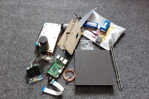
After that I did other things for a long time. But some months ago I wanted to rebuild the machine from scratch. This entry is about this rebuilt version. The 2 videos on the top are just meant for a quick history on how it started. So, what changed? I no longer use servos but Nema17 stepper motors for the movements. I bought some belt drive components and ball bearings. I used those to convert the axial motion of the steppers into linear motion. It's the same setup as in an inkjet printer.
The main controller of this project is a Raspberry Pi 2. It has a Raspberry Pi camera module NoIR connected to it. Because it is NoIR, there's no IR filter on the thing. I originally planned to use infrared light to brighten up the ball in front of the camera. But it didn't work well. The IR elements I used were way to weak. The infrared noise in the background (sunlight etc.) would overweight the infrared light getting reflected from the ball. Another problem was, that the IR signal gets picked up on the red-channel of the camera. This means that even if there is no infrared noise from sunlight, the infrared light's intensity still has to surpass the normal red light's intensity to be recognizable. So that idea got dropped. I ended up using the green-channel on the camera with green light from a RGB Power LED pointed at the ping pong ball. Sure enough, normal white light would've done the job as well, but I just happened to have a RGB LED laying around so I ended up with green.
Another important thing is this: You might be asking yourself "Why did you use a light source anyway? Couldn't you just use OpenCV and get the thing to recognize the white ball with normal lightning conditions?". The answer to this is: Probably not. At least not with a Raspberry Pi 2. The reason being that we need 90 fps real time image processing to track that ball. The image processing has to be done fast. I didn't really use OpenCV for anything at this Point in time but my guess is, that it wouldn't work well, because I don't think I could get the processing rate up to 90 fps with OpenCV. Maybe I am wrong about this, but it was my gut feeling, so I went on to program a really simple algorithm that could take care of the image data really fast. The algorithm looks directly at the data stream, so no conversion to a different datatype (e.g. NumPy) is needed. This is one reason this algorithm is quite fast. The other reason is, of course, that it is a dumb algorithm. All it does is look for a clump of bright green pixels on a fairly black background and then compute the center of it.
After the algorithm extracted 3D coordinates out of the images it examines that data and, in the case the ball is going downwards and gets quite near to the racket, it uses that specific data set in a PID controller to get some useful correction values on the racket as the ball is moving towards it (the machine tries to get the ball into the center of the racket). The movement values are then sent to the Arduino Uno over the serial port....
Read more »


 Muth
Muth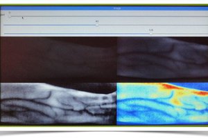
 Myrijam
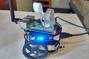
 Brenda Armour
Cool and fast