 Myrijam
A chronic disease which requires frequent venous puncture is hemophilia. In the blood clotting chain, one or more essential enzymes are missing or build in a non-working way due to DNA corruption. This can cause severe bleeding into joints, muscles or inner organs and is potentially live threatening if the rest activity of the clotting factors is below a few percent. Today, most of the clotting factors can be artificially synthesized through biomedical engineering (cell cultures with a changed DNA produce them), but they still have to be administered externally – injected into the blood stream by venous puncture. Venous blood vessels used for medication are not always easy to recognize and if the needle is not secure in the vein, it must be punctured again at another point. Here our project comes into play: Using NIR (near infrared) Illumination and real-time image processing, we can make the veins more visible, allowing easier Access, less pain and more confidence for medical personell and patients.
The veins are illuminated with IR light (950nm) and the back scattering is captured by the Raspberry Camera (the one without the IR-filter). You can use old analogue film tape as a filter to block visible light and let only pass IR- light. The camera picture is processed in several stages to get an improved distribution of light and dark parts of the image (multistage local adaptive histogram equalization). The reason to use near IR illumination lies in the optical properties of human skin and in the absorbance spectrum of Hämoglobin.
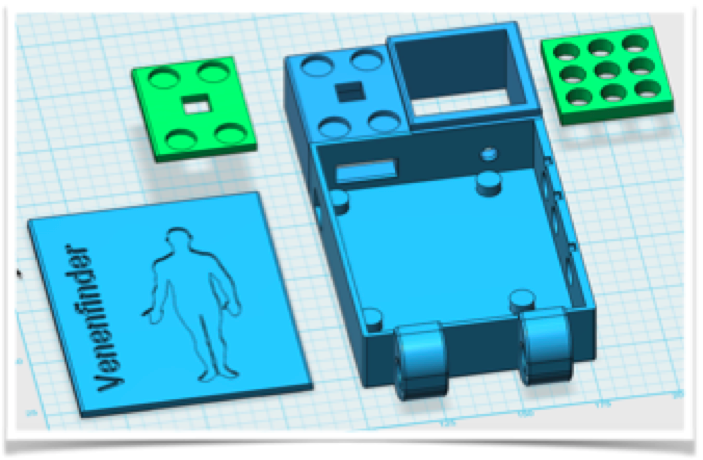
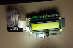
After several tests (with IR light but also with thermography and different visual wavelength) we we first developed two prototypes for computer-assisted venous localization. One uses a 3d printed case for the Pi and a 7 inch Screen, the other is an add-on module for the Pitop CEED. With these steps we moved the development away from breadboards and proof-of-concept stages to concentrate more on image quality and user handling. Both differ, too, regarding to the camera system used – one works with the PiCAM, the other with a modified webcam. Both have their own pros and cons…
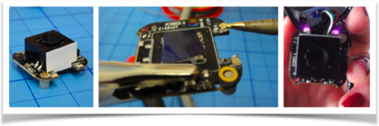
The Raspberry PiCam can be used without further modifications. However, this camera offers only a fixed focus and cannot adjust to the image scene automatically (only brightness etc.).
Another possibility is the modification of a webcam – removing the IR blocking filter. It is a bit tricky, but we have been able to use such a camera from my previous research project (“eye controlled wheelchair”).
The Results:
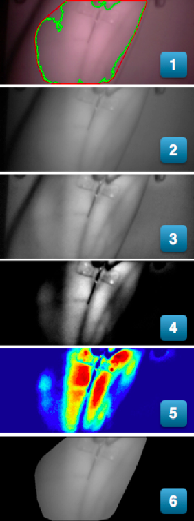
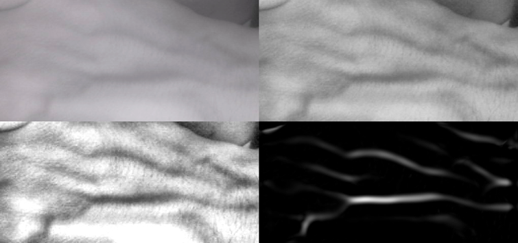
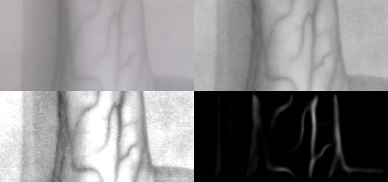
Figure 9: Results of the filter stages
At the beginning of the program, the graphical user interface is constructed, in which, in addition to the converted video stream, sliders are shown for parameters like Brightness and filter adjustments. In a continuous loop, single images are read by the camera and the filters are applied.
In the first picture, the imported camera image is visible - the vein is already visible in the infrared light, as well as the cannula, which is simulated for the purpose of the puncture. Fig. 2 shows the result of the gray scale conversion since no color information is required and the data needed can be reduced to one third. The next step is to adjust the brightness distribution with an openCV filter. The result is a much clearer visual representation in Fig. 3. The next picture shows the result of the manual filter setting, in which brightness information below and above the threshold value is discarded and the range of brightness is also stretched over the entire range (0-255) from the selected range. The following filter converts the gray scale image into a false color image in which the relevant information is not contained in the brightness but in the color profile. As a result of the discussion with medical professionals, we have installed the last filter stage in which a depicted arm or a hand...
Read more »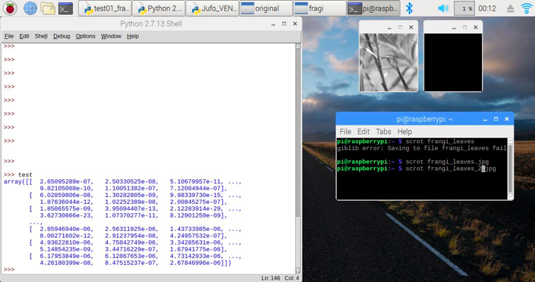


 Brenda Armour
 volzo
volzo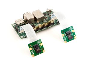
 Eugene
In my experience and opinion, establishing IV access - whether peripheral or central - is an art form which requires skillful technique and knowledge of basic human anatomy. With that being stated, I have seen many of my colleagues completely botch attempts at something as simple as drawing an ABG from the radial artery. <sigh>