 David Scholten
Capacitors are wonderful things - They allow the release of energy at tremendous rates allowing for endless entertainment with rail-guns, spark-gaps and all sorts of pulsed power applications.
Batteries, specifically high power lithium variants, offer a continuous source of high power for relatively long periods of time. However, the pulsed power provided is nothing compared to that of a standard capacitor bank.
Super capacitors lie in between lithium batteries and capacitors in terms of capability. They exceed regular capacitors in term of energy storage, but they have nowhere near the energy storage of lithium cells. Surprisingly, super capacitors have pulsed power capability below (or near) that of both regular capacitors AND lithium cells (for my super capacitor bank, one of my equivalently sized lithium polymer batteries had 4 times the "rated" pulse power capability). Additionally, like lithium batteries, super capacitors must be connected in series and carefully charged/balanced. Finally, super capacitors have a voltage curve that is proportional to the remaining stored energy and require DC-DC converters for practical application.
HOWEVER! Super capacitors are resilient!
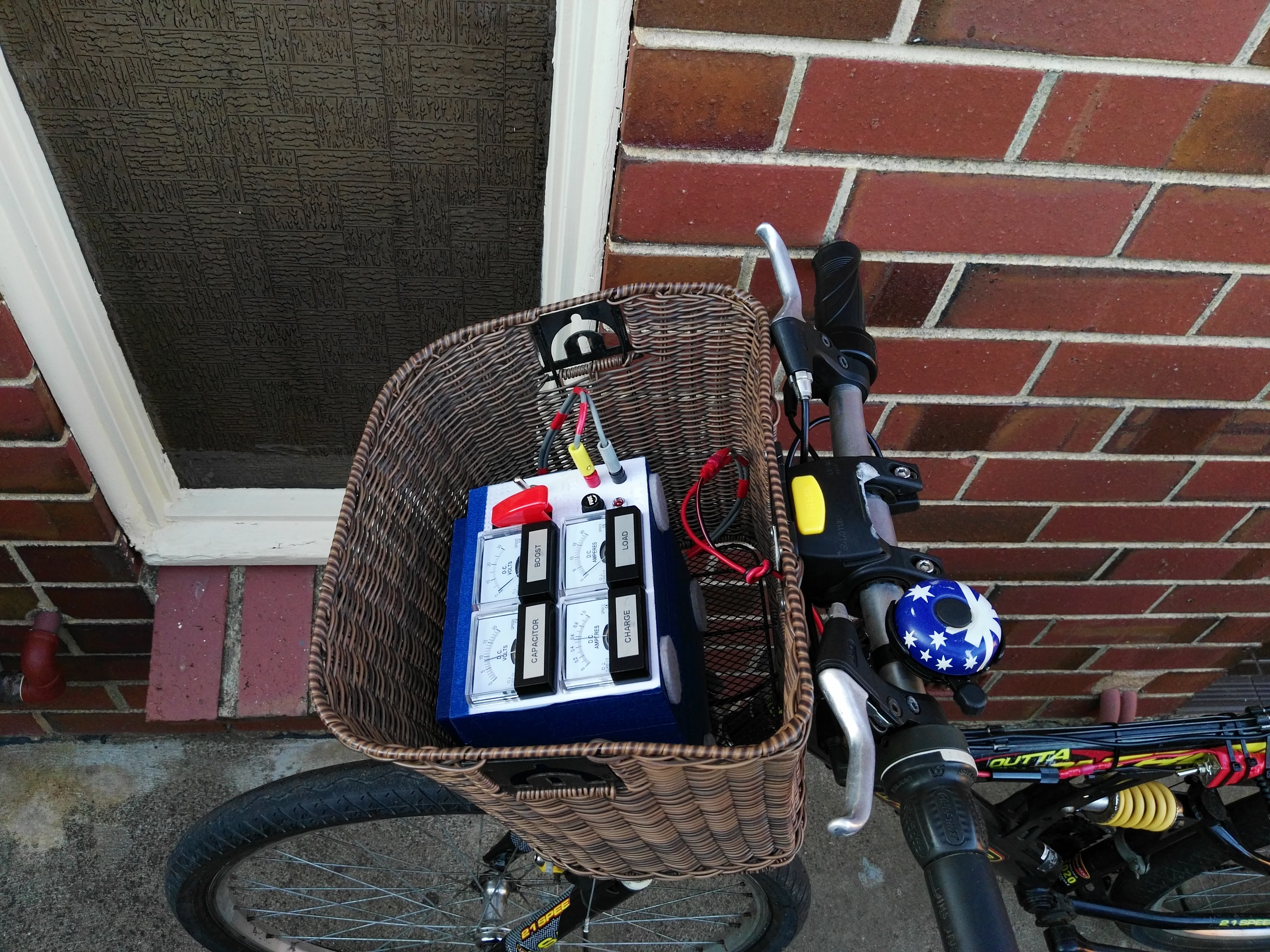
A super capacitor powered device lasts practically forever (compared with batteries) and is useful in rugged applications requiring a slow charge but fast discharge. An electric bicycle with a super capacitor bank would be able to charge as you ride from a motor and then give back a sizeable amount of power and energy to assist with hill climbs when required.
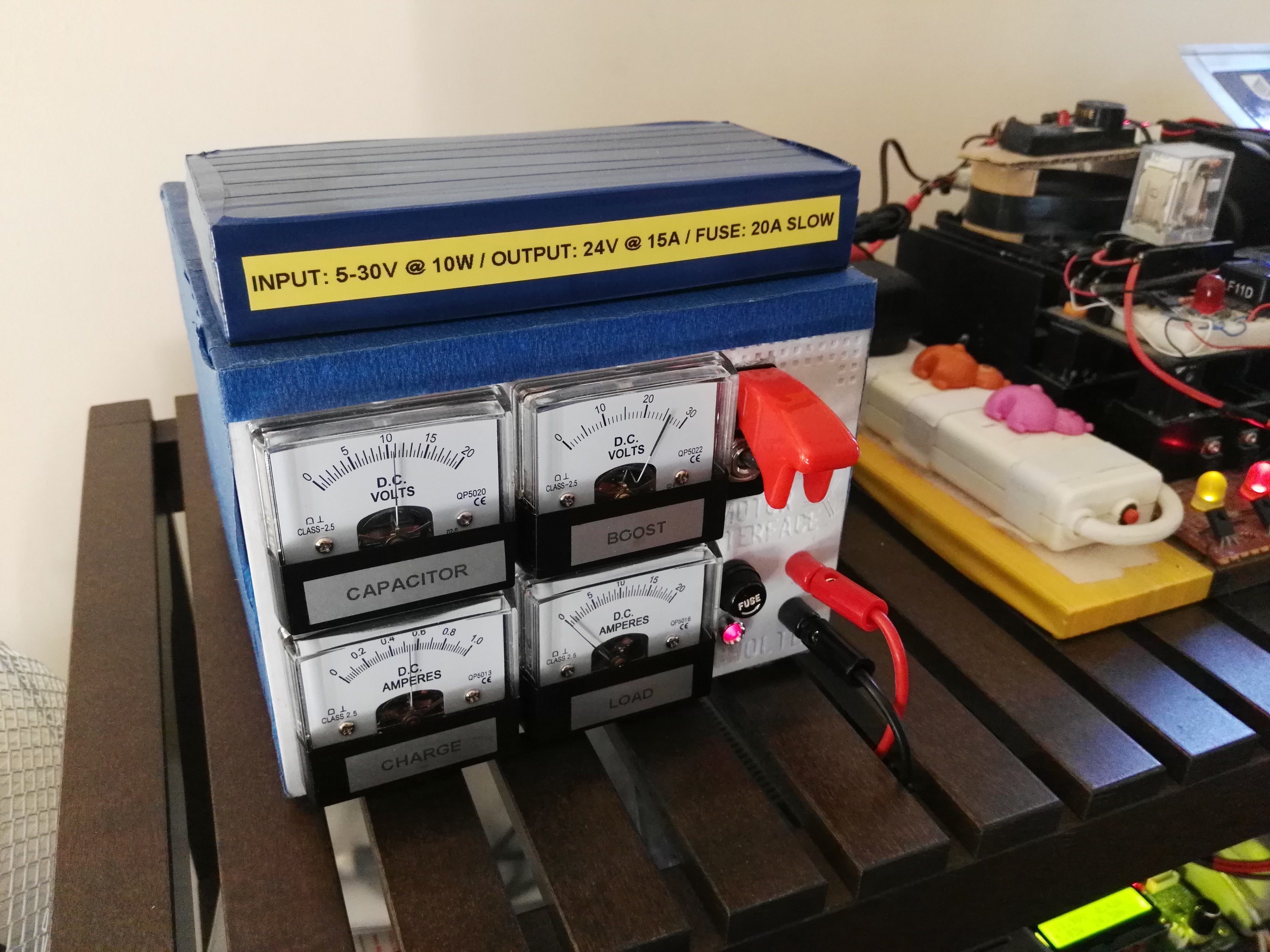
Looking in to this I quickly came to the realisation that charge balancing and control is a serious project. A decent charge controller would first charge the super capacitor strings with the maximum amount of current until one capacitor hits a voltage limit. From here the charge current would be reduced to whatever the attached balancing board can withstand. The balance boards in the super capacitor bank utilised only allow for a 0.8A balance. As I only implemented the balance board, my charge current is limited to 0.8A (0.6A actual) for the whole charge cycle. For my 16V super capacitor bank, this translates into a charging power of about 0-10W. What's done is done and that is the charging limit for my super capacitors.
This then leads to how the project came about. If I can only charge at a maximum rate of 10W, why not just use AA batteries instead of syphoning power from the rider through the DC motor? It’s far easier that way.
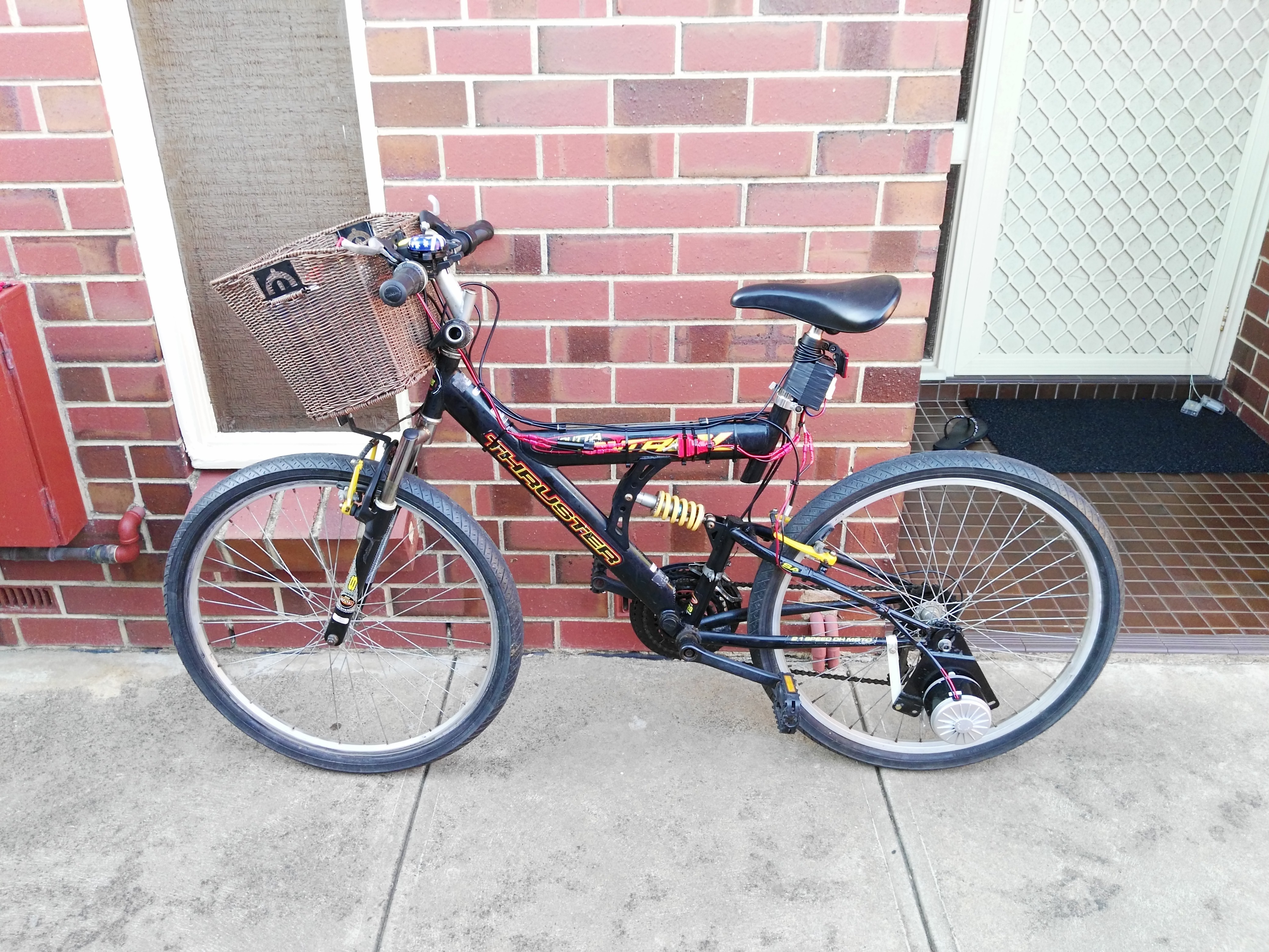
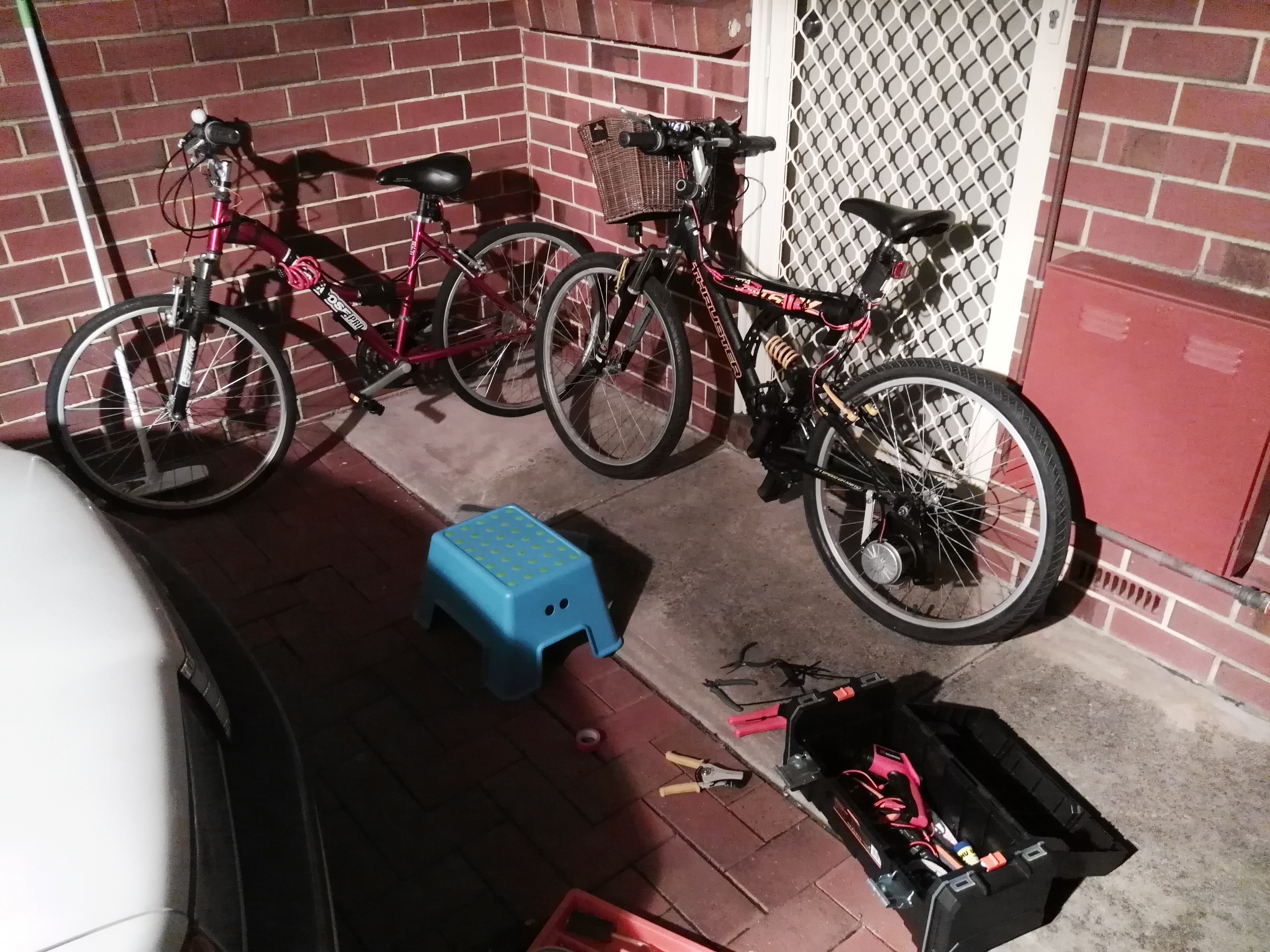
Thus, the AA electric bicycle was born.
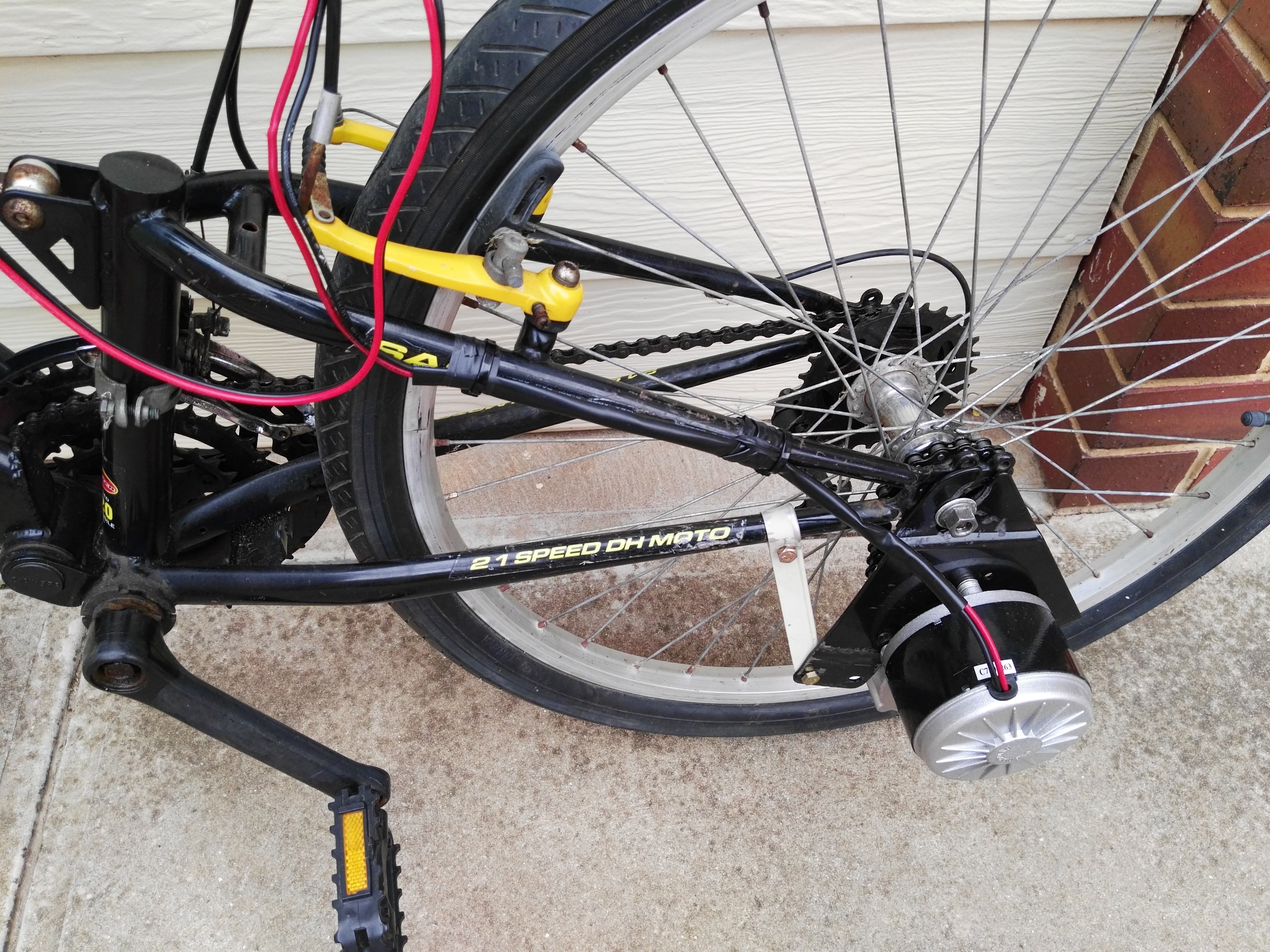
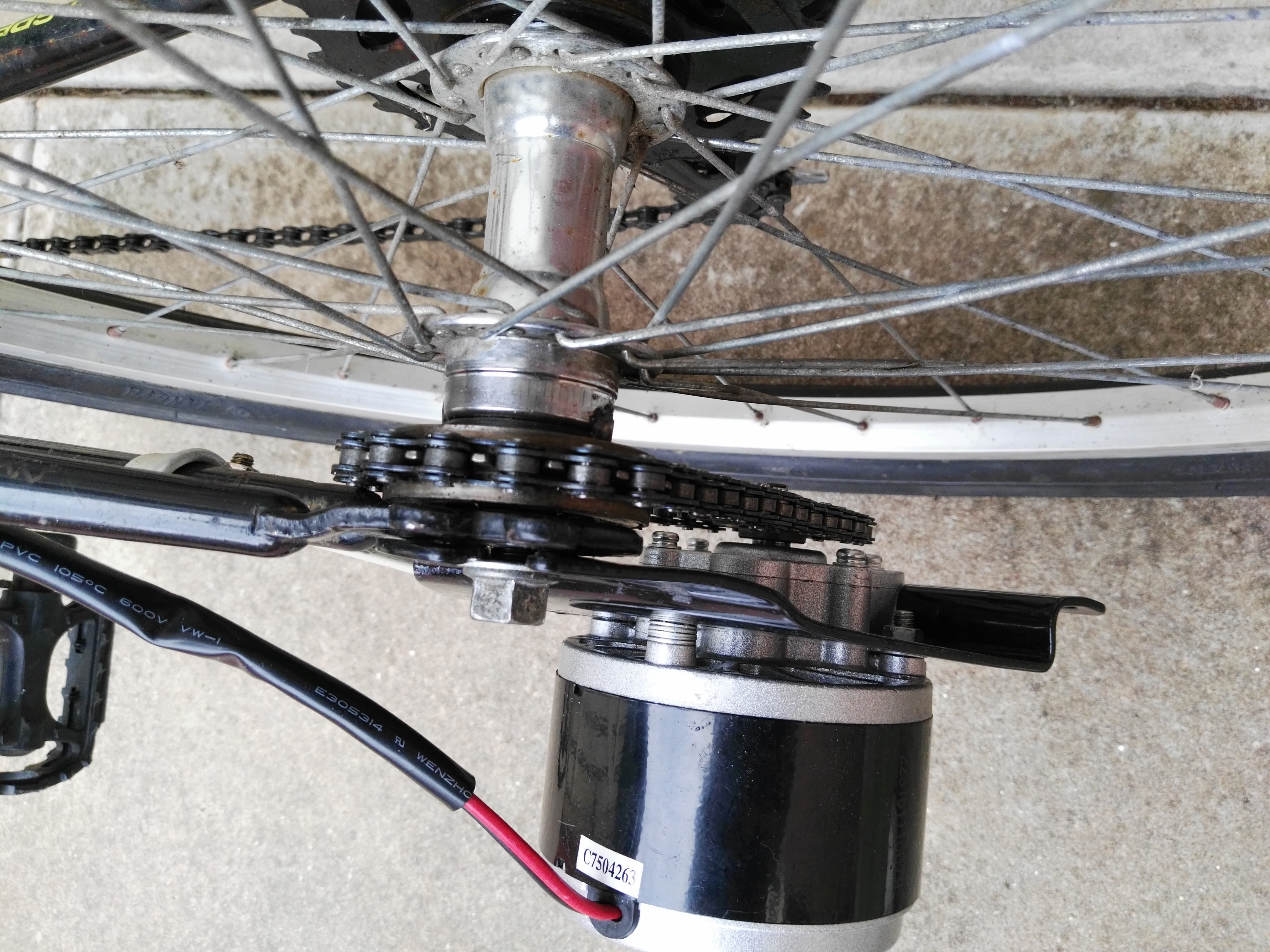
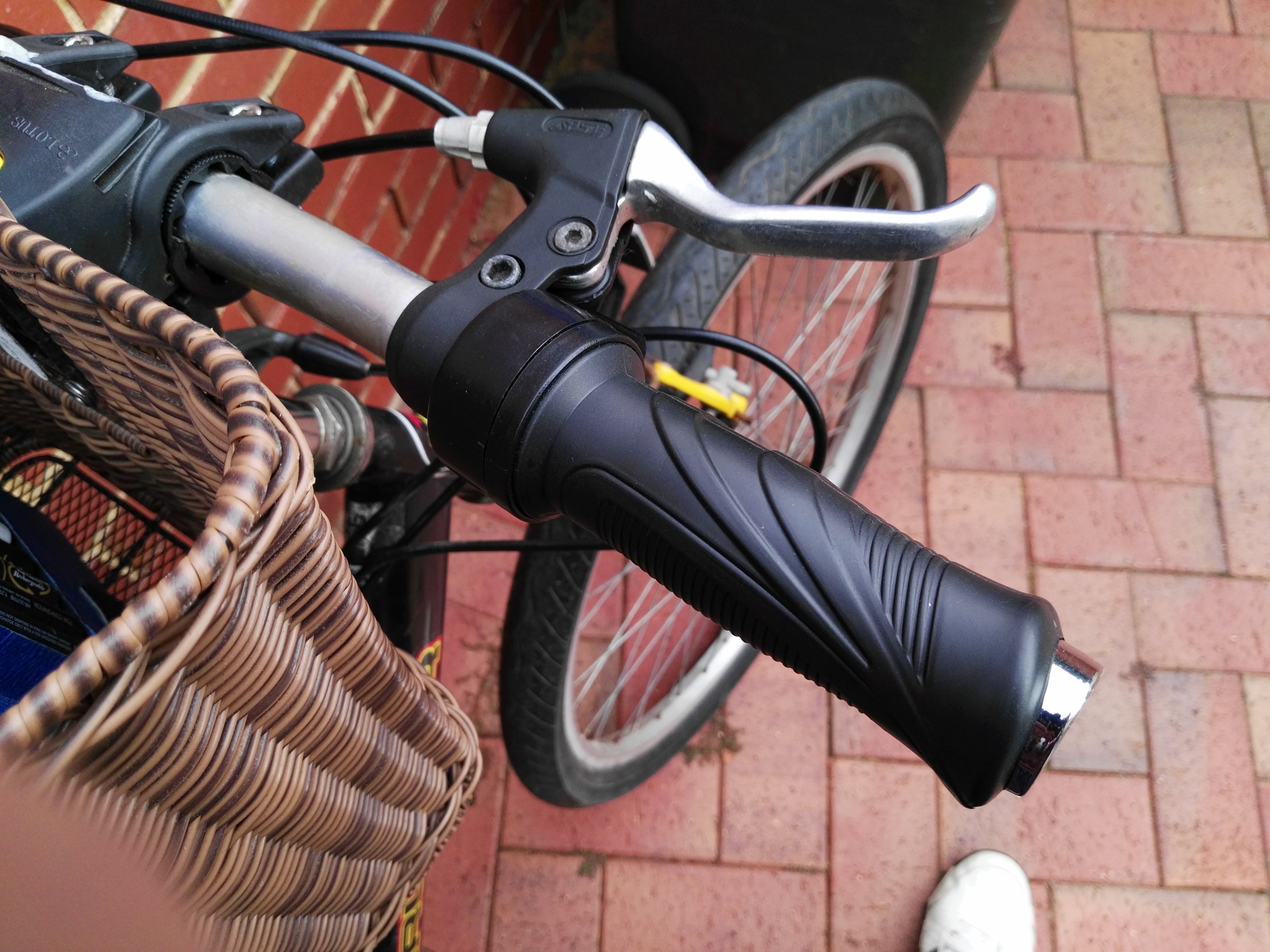
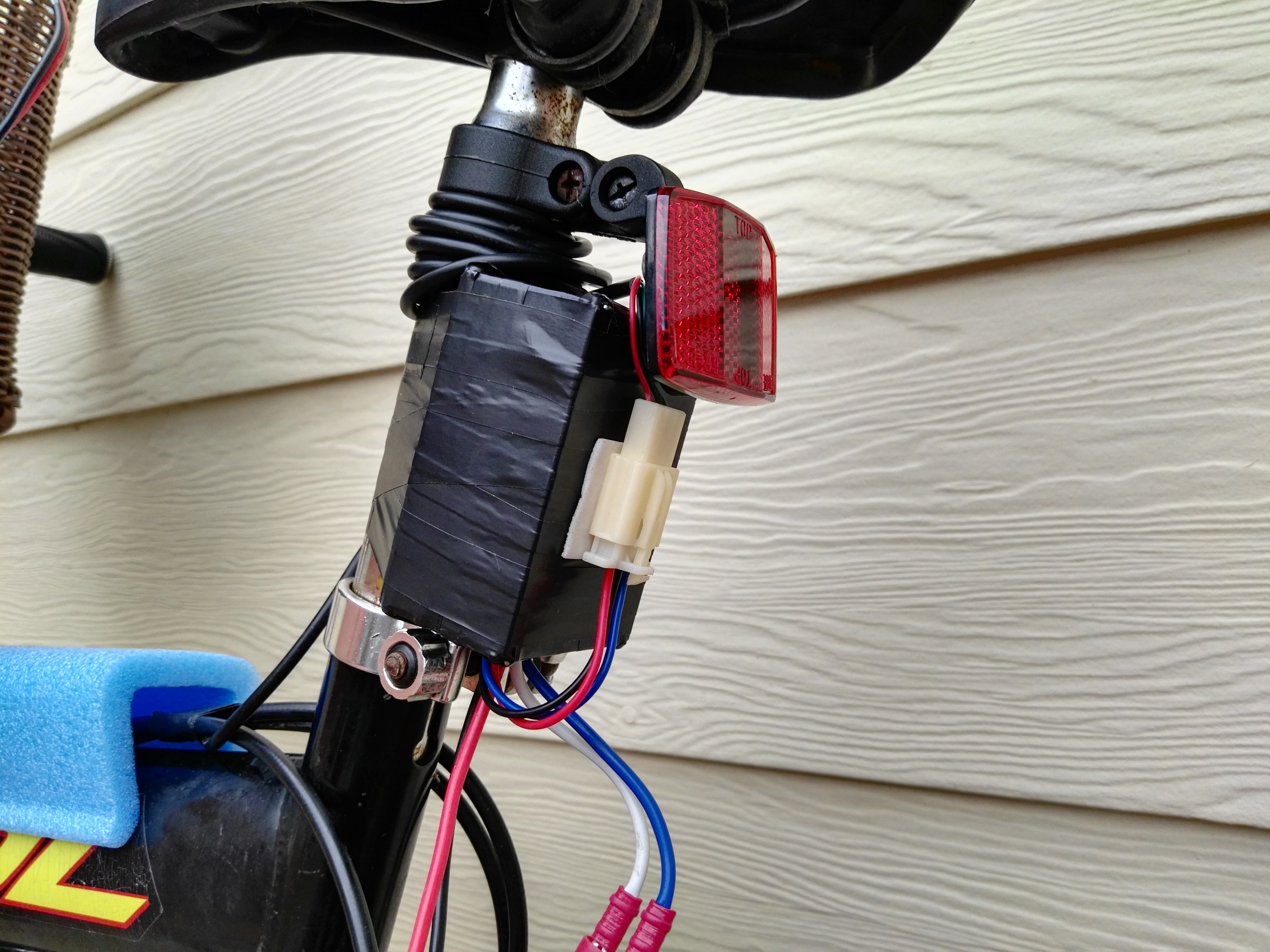
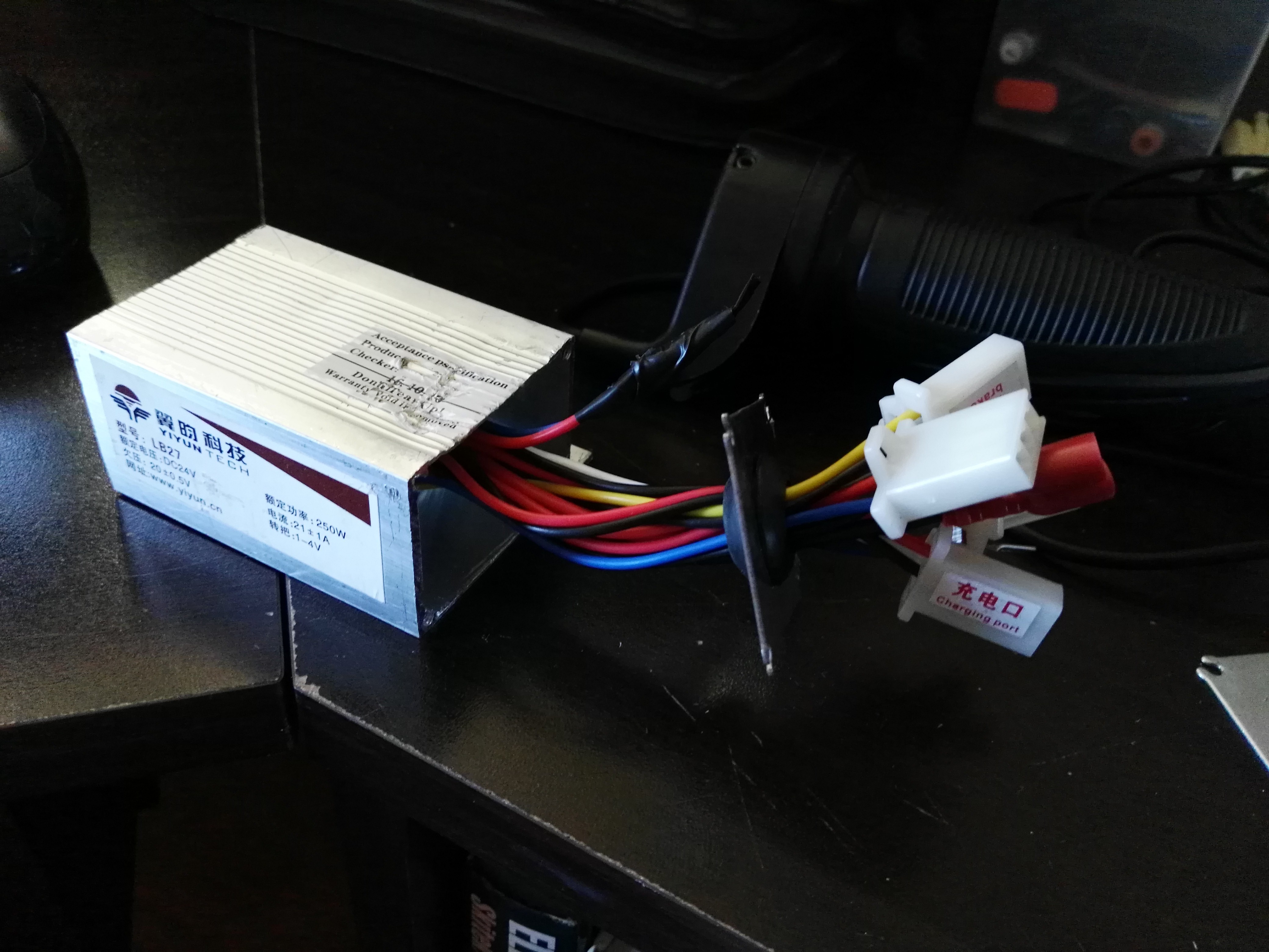
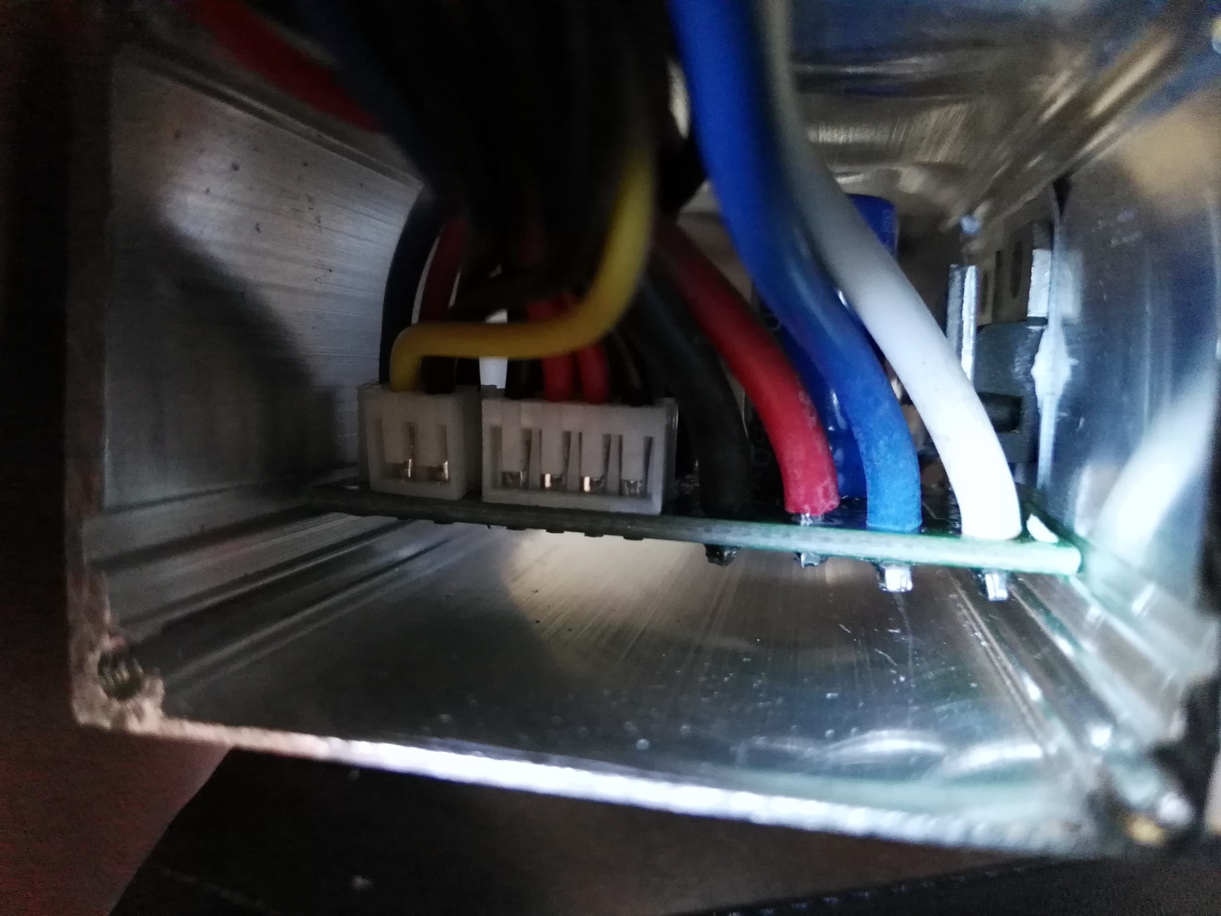
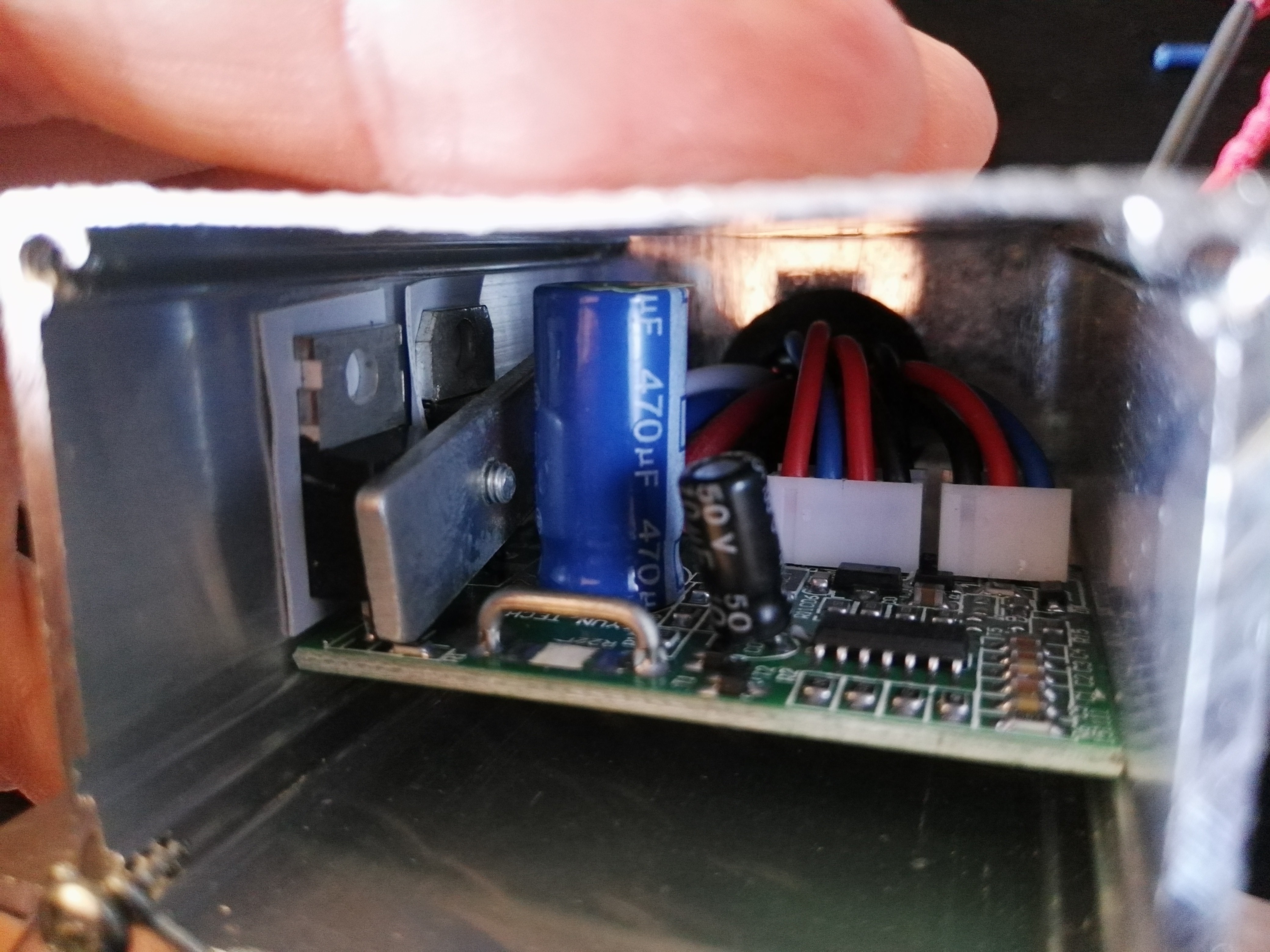
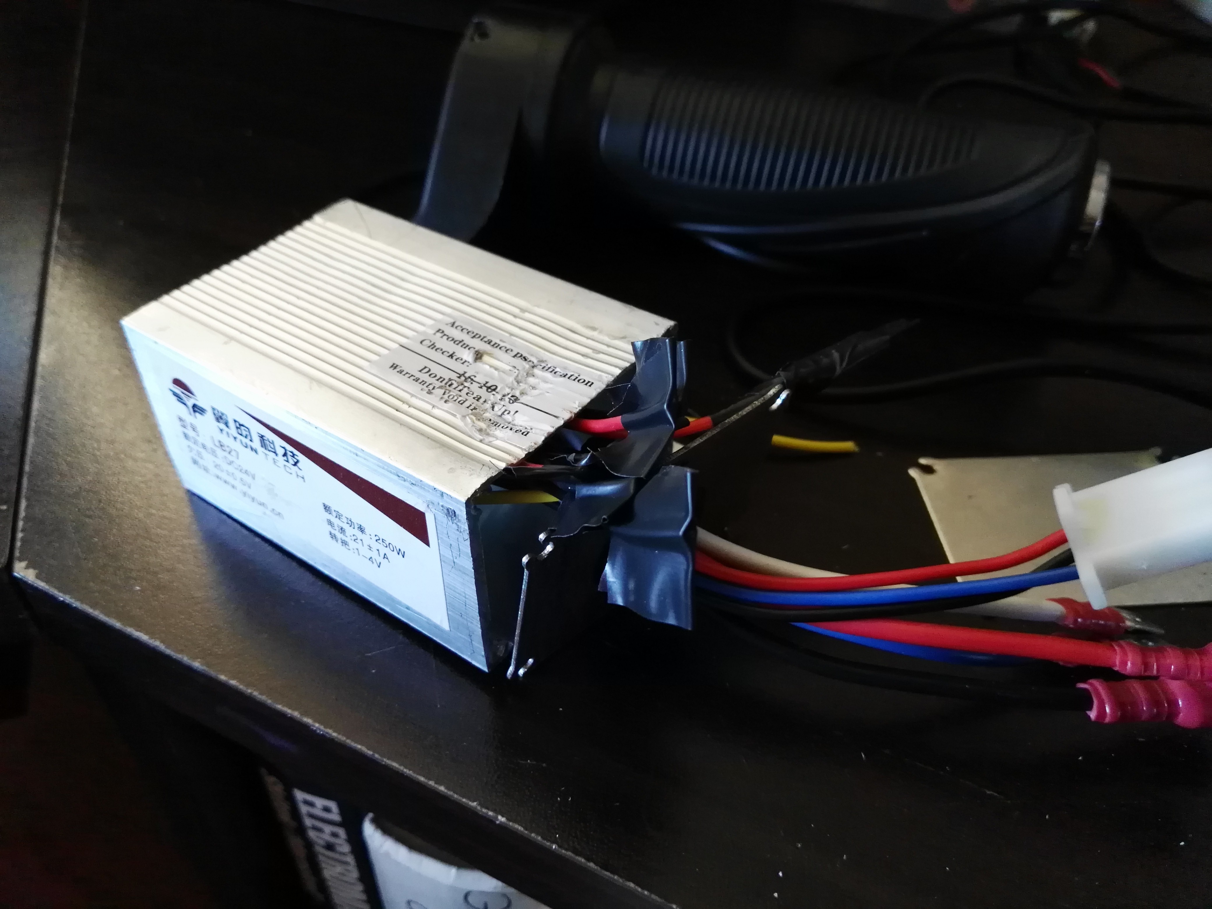
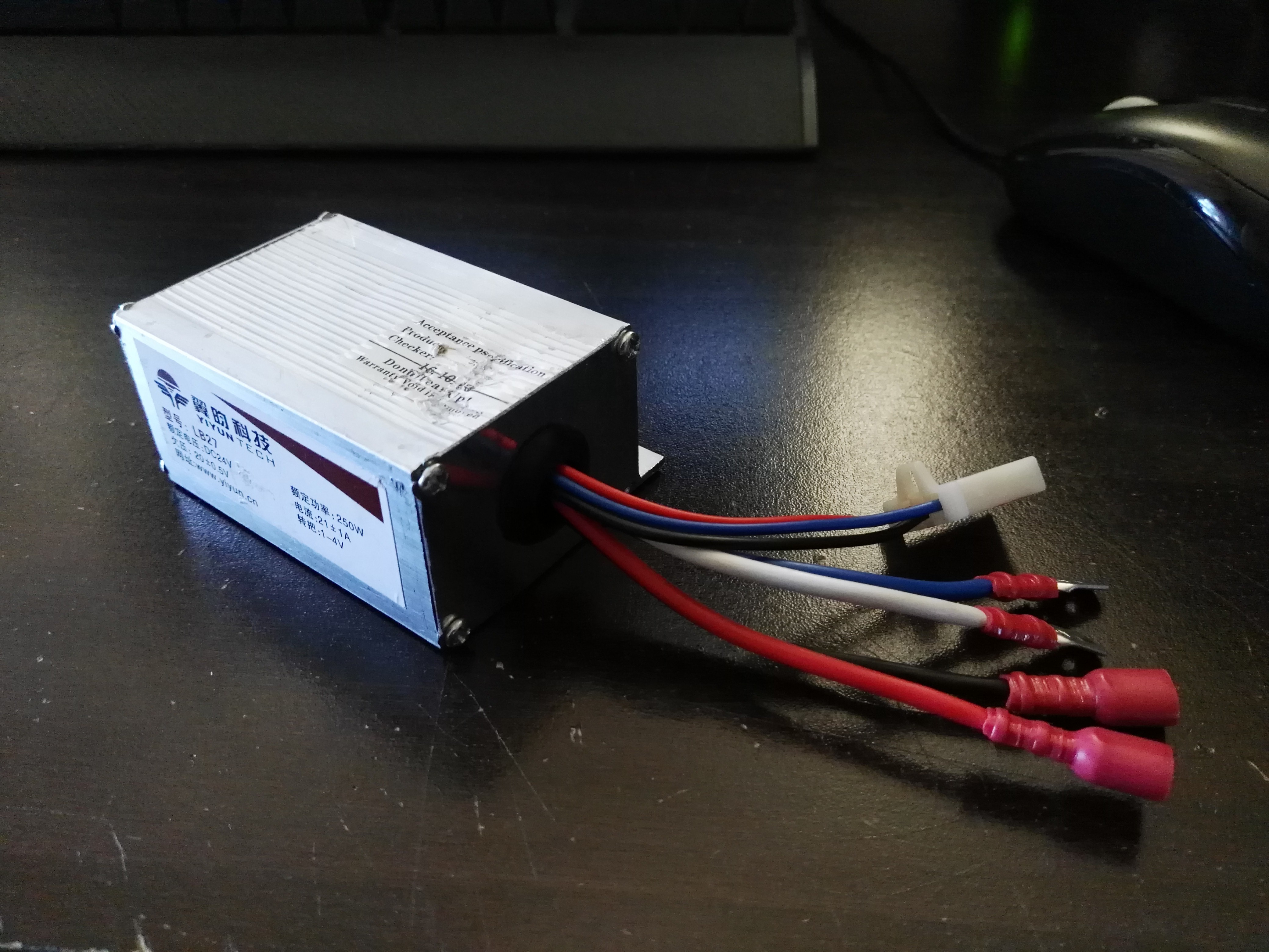
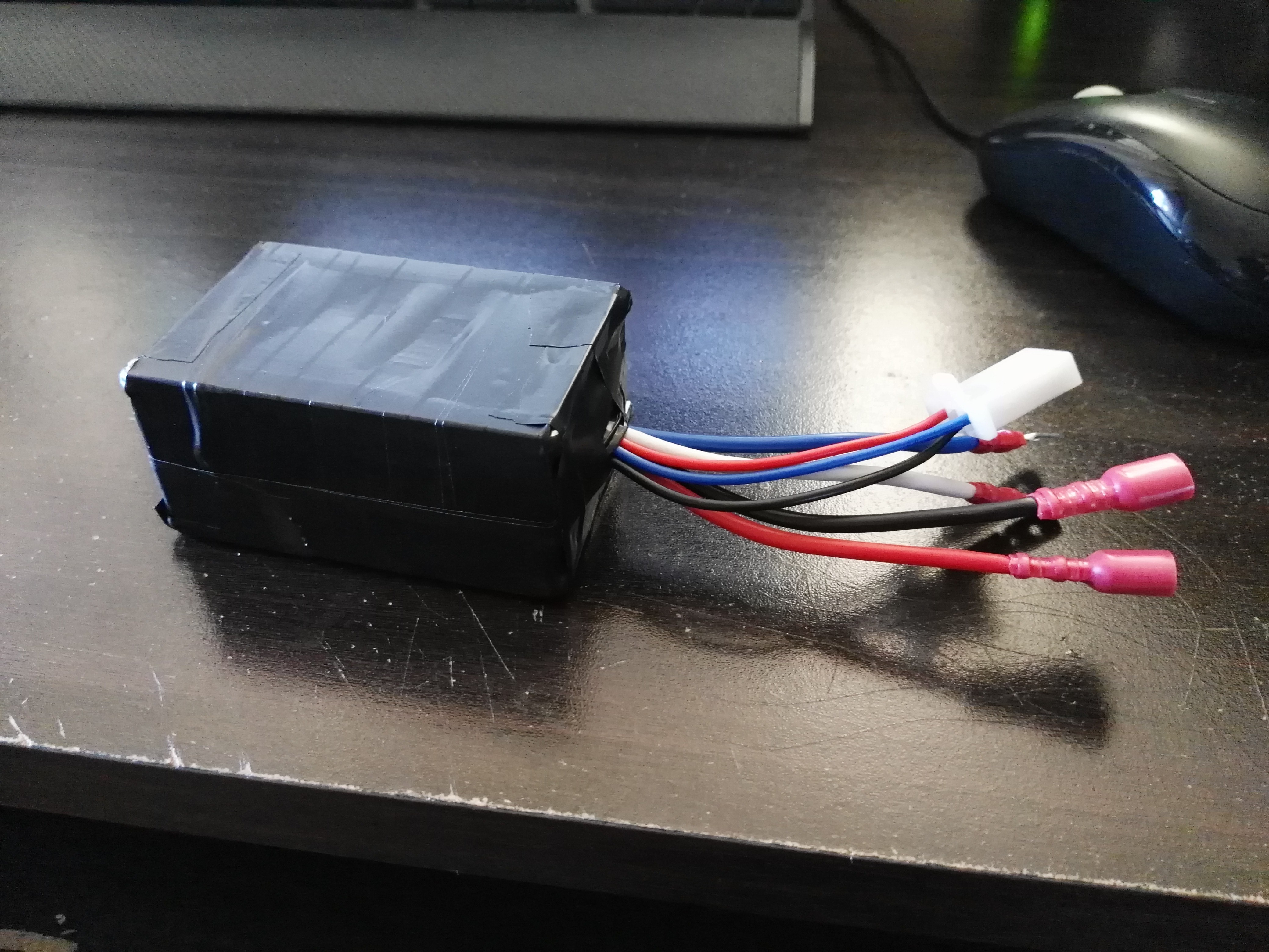
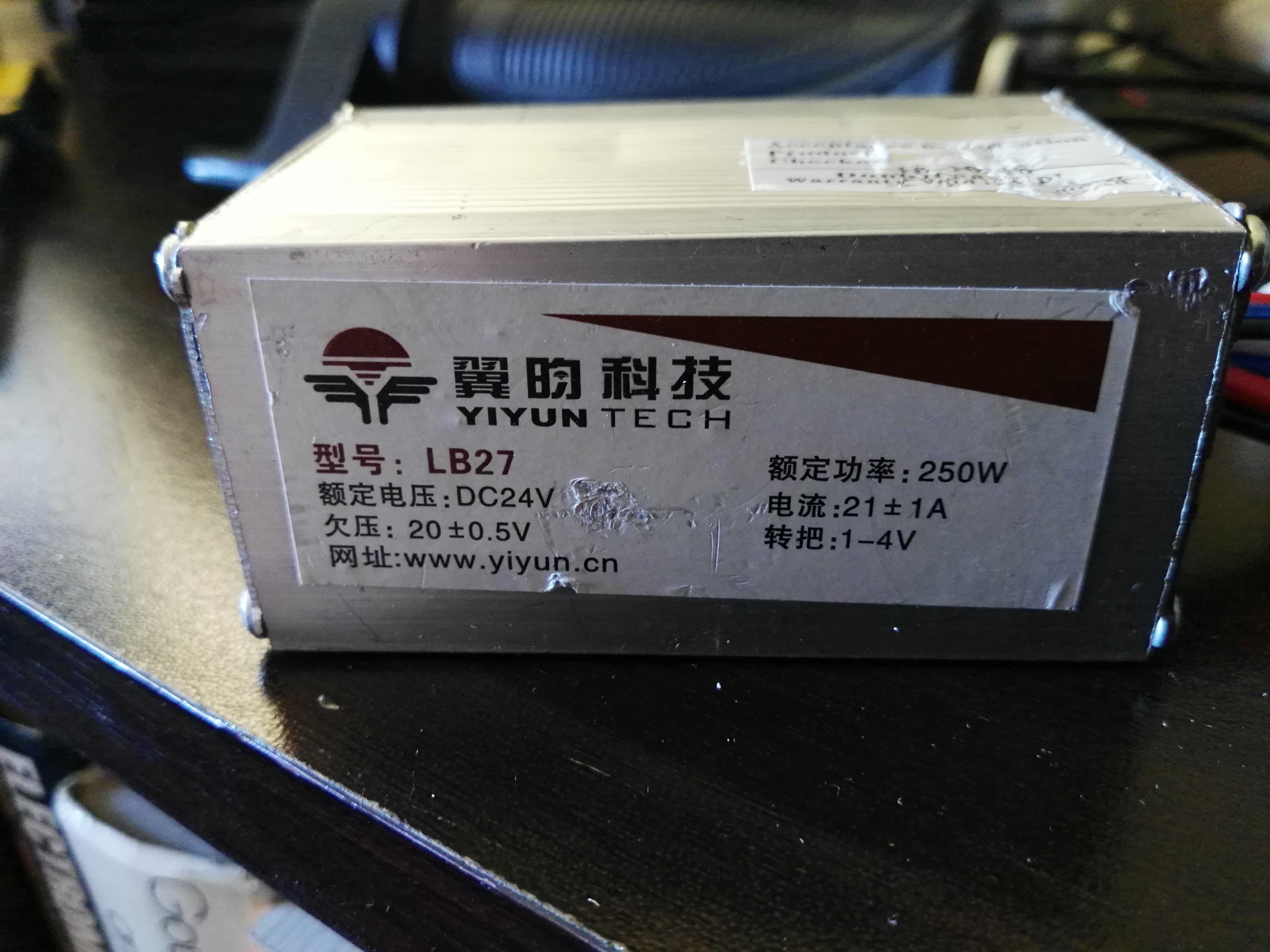
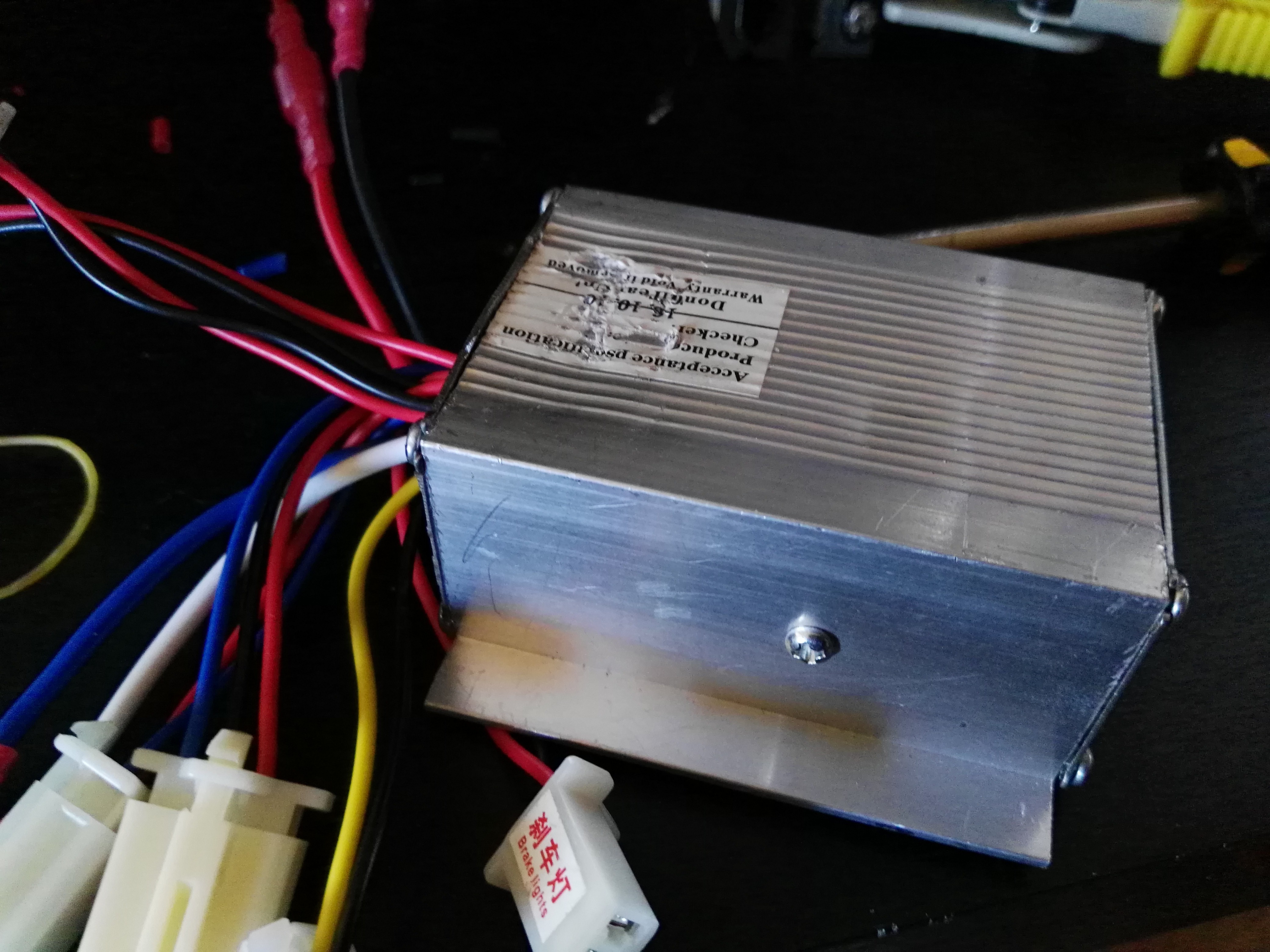
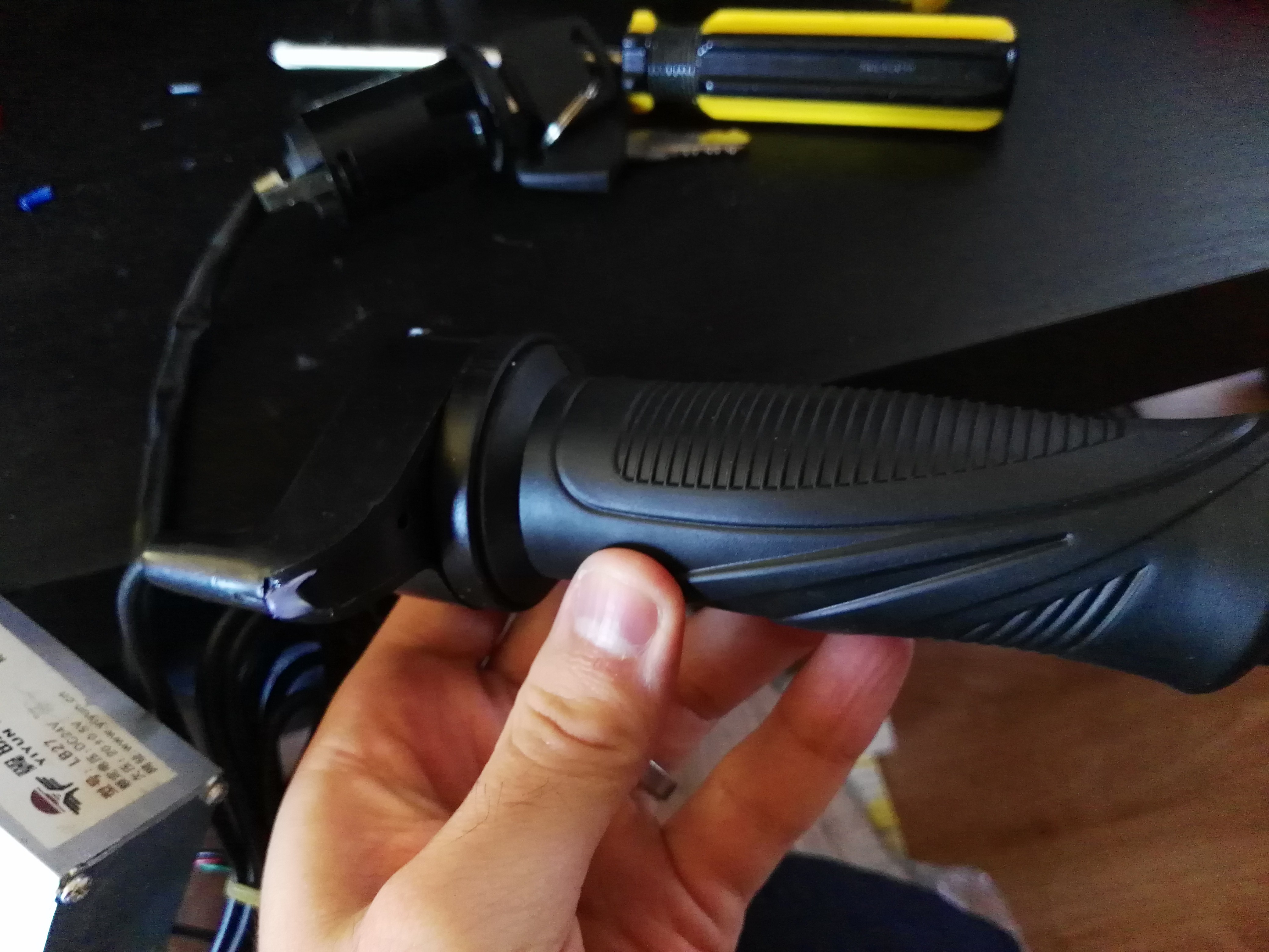
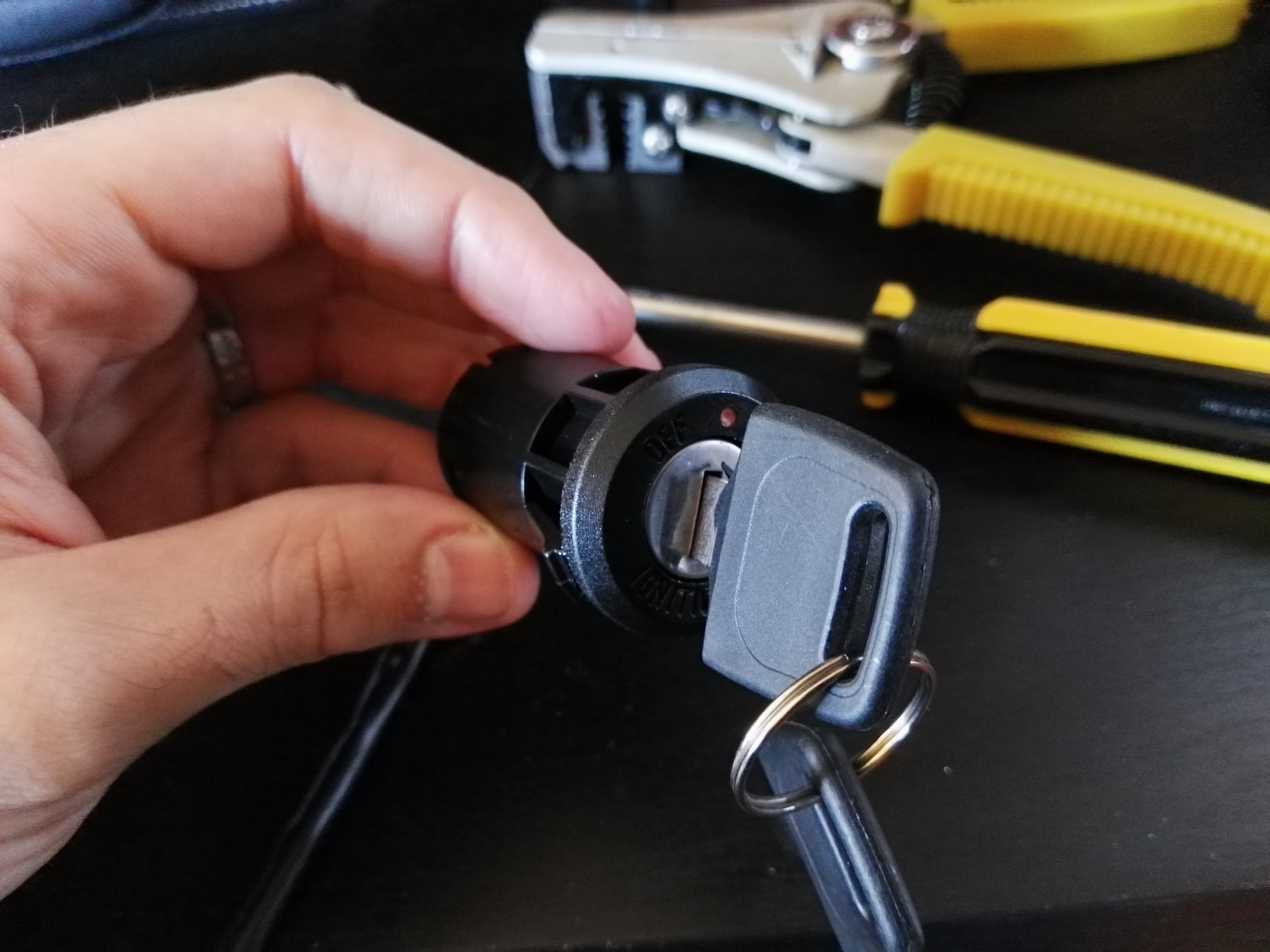
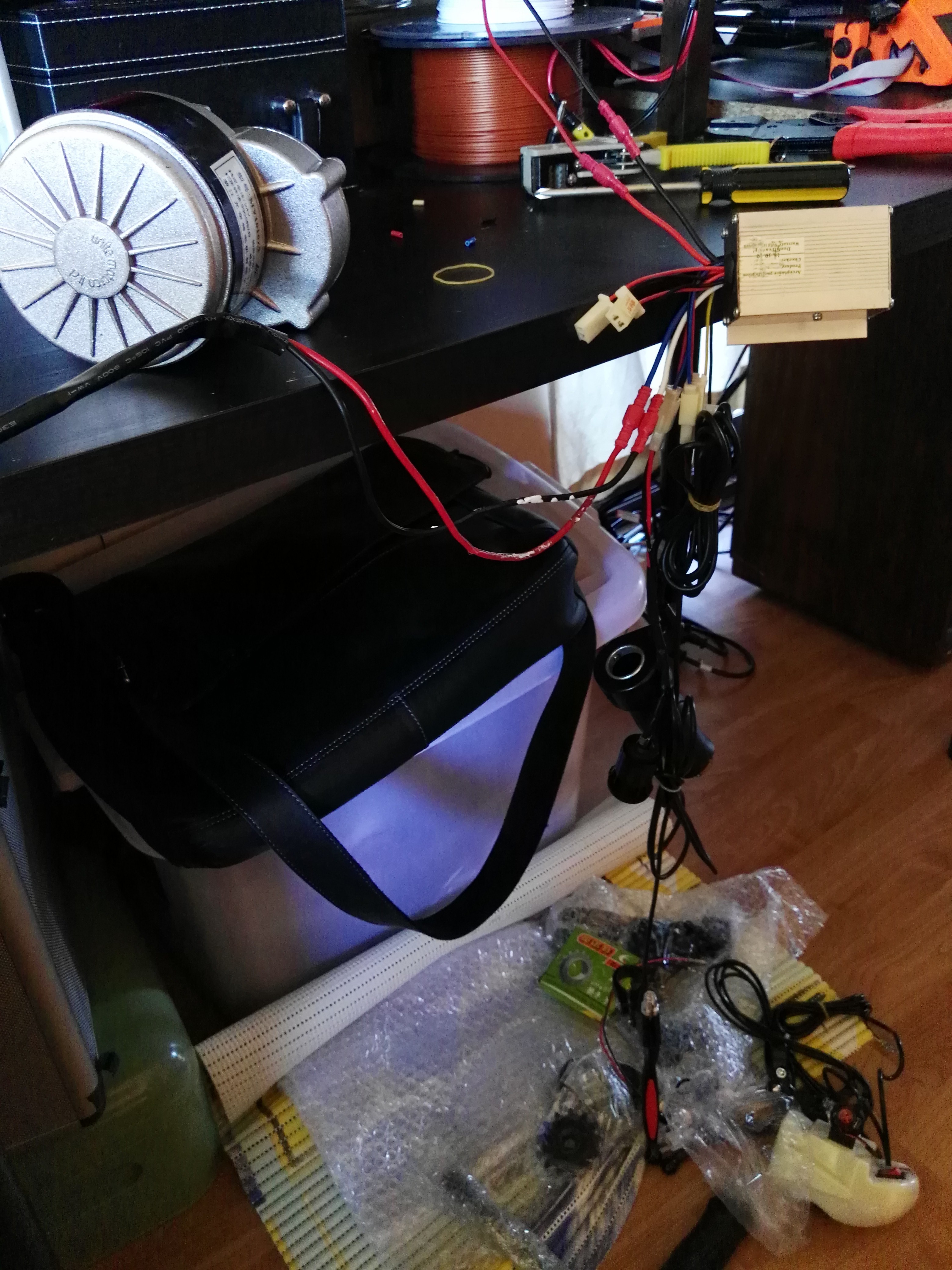 For my case I am interested in only the motor, DC-DC converter,
throttle control and anything that helps connect these devices to the bicycle.
For my case I am interested in only the motor, DC-DC converter,
throttle control and anything that helps connect these devices to the bicycle.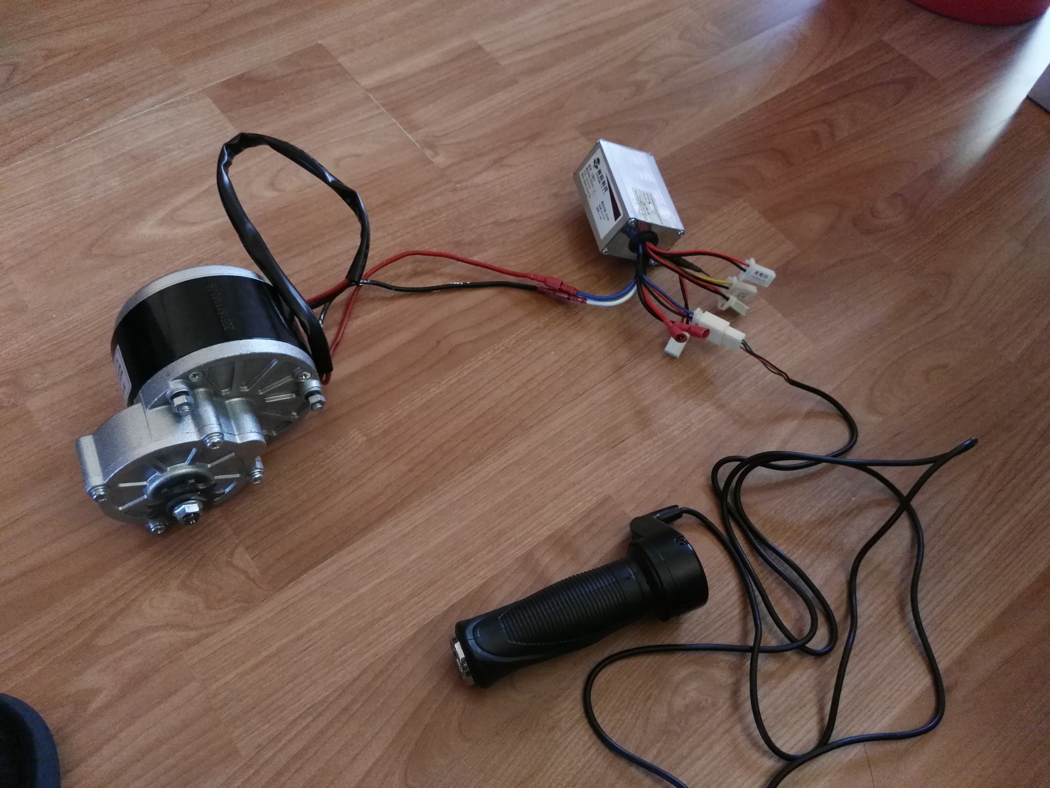

 Discrete Electronics Guy
 Mitja Breznik
 sciencetoolbar
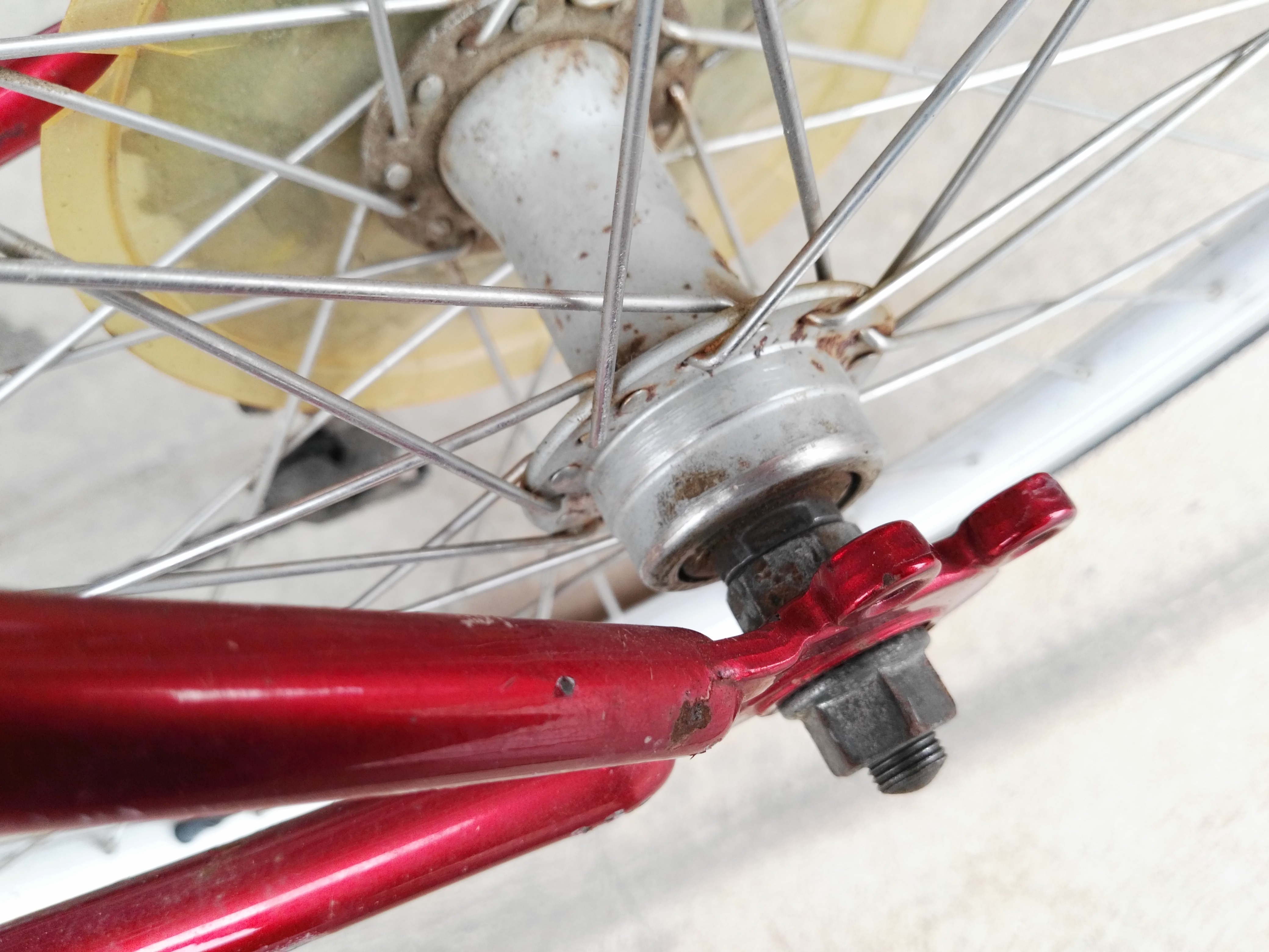
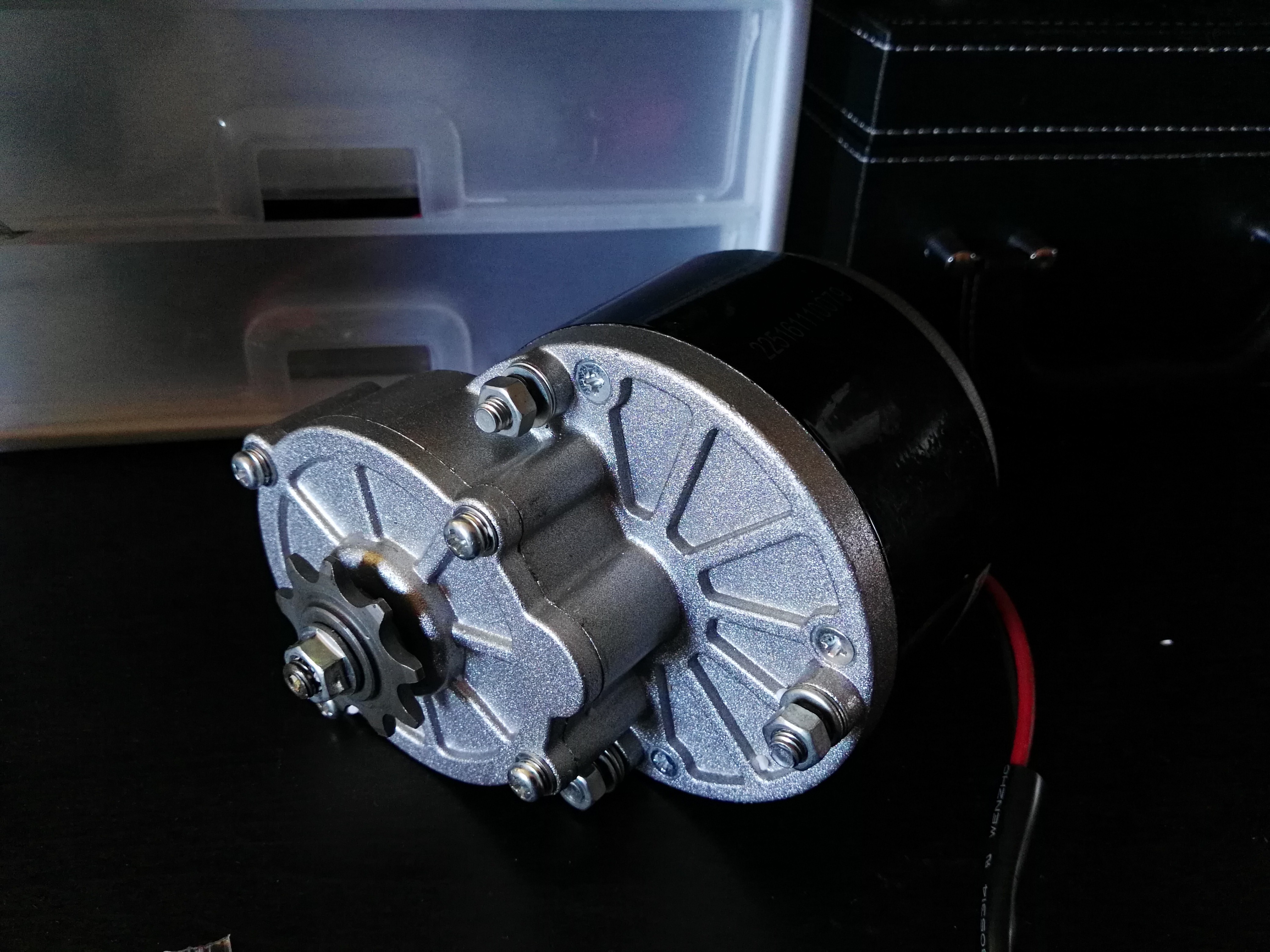
Having some problems mounting the motor to the bicycle frame! The entire kit assumes a threaded spoke hub and so it looks like I'll be buying a replacement wheel.