Close
0%
0%

A Super Capacitor Pulsed Power 24V DC Supply

A power supply for the soon to come 200W+ AA Battery Electric Bicycle

Similar projects worth following
EDIT: See https://hackaday.io/project/21058-the-200w-aa-battery-electric-bicycle for the bicycle!

Ever since I was a child I have liked the idea of pulsed power (shields are charging sir), but I have never followed through on that interest. What I want to make is a portable and high power (20A+) 24Vdc source that runs on 1 or two 9V batteries (or PV). Using 4000-5000 joules of super capacitors, charging circuits and a LOT of boost converters at the output, this is certainly possible!

However, to avoid the territory of Lithium Polymer batteries, I want to apply this device into a situation where it needs to last a long time in harsh conditions. I'm thinking an electric bicycle.
So there you have it, this is the power supply for a soon to come "9V Electric Bicycle". In this case the 9V batteries may not even be needed as the capacitors can be charged from the bicycle

Final System as Completed (20/11/2016):
>Charges from 10 AA batteries instead of 9V batteries.
>Output Is scaled back from 20A to 14A "continuous" (for the majority of capacitor voltage curve)
>Relays were not used and there is a reliance on heavy duty switches instead.
>Wireless relay control is therefore removed.
>Capacitor charge current was set to 500mA. If this is set too high then the batteries will be declared as "flat" at an earlier point. For example, if this is set to 10A then the boost/buck converter will immediately drive the voltage curve of the batteries into the ground and declare them as depleted immediately.

The Youtube video from the broken link can be seen below:


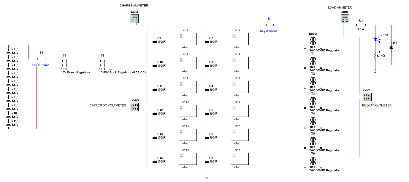
Schematic.bmp

The final schematic of the entire system as implemented.

Bitmap Image File - 2.43 MB - 12/04/2016 at 03:56

Preview

BoostHolderSmall.stl

A reduced rack for holding the boost converters in a convenient way (holds 7).

sla - 6.72 kB - 10/30/2016 at 04:34

Download

SC Face Panel.stl

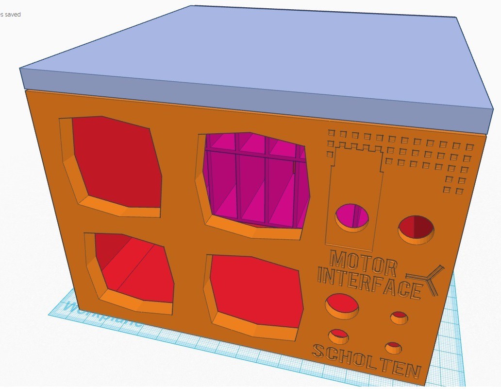
The face panel of the main box containing all of the switches and panels.

sla - 217.76 kB - 09/30/2016 at 09:46

Download

BoxBase.stl

The primary portion of the box (bottom, two sides and back).

sla - 19.71 kB - 10/16/2016 at 01:49

Download

BoxLid.stl

The lid of the entire box.

sla - 4.28 kB - 10/16/2016 at 01:49

Download

View all 6 files

View all 18 components

  • Electric Bicycle Underway!

    David Scholten04/23/2017 at 13:56 0 comments
  • Wrapping Up This Project

    David Scholten12/04/2016 at 04:14 0 comments

    Although the project was finished a week ago I still was missing the most basic piece of information - The circuit schematic. It's not perfect and yes, it was rushed, but it illustrates the system none the less:

    A higher quality picture is attached in the project files (.BMP).

    Being my first Hackaday project that I have posted I have come to greatly respect those that can present their projects in a simple way for others to enjoy. I've found it tricky to write about the fun that I've just had - because I'd rather just have more of that same fun instead. Regardless, communication of this sort is something that needs to be practised to be improved.

    Though this is the end of this project, I plan to come through on the project's subtitled promise of a AA battery electric bicycle. Once Christmas is though I will be ordering a basic electric bicycle conversion kit to make use of the super capacitor pulsed power supply.

    Until then - Happy holidays!

  • The Project is Finished

    David Scholten11/20/2016 at 07:38 1 comment

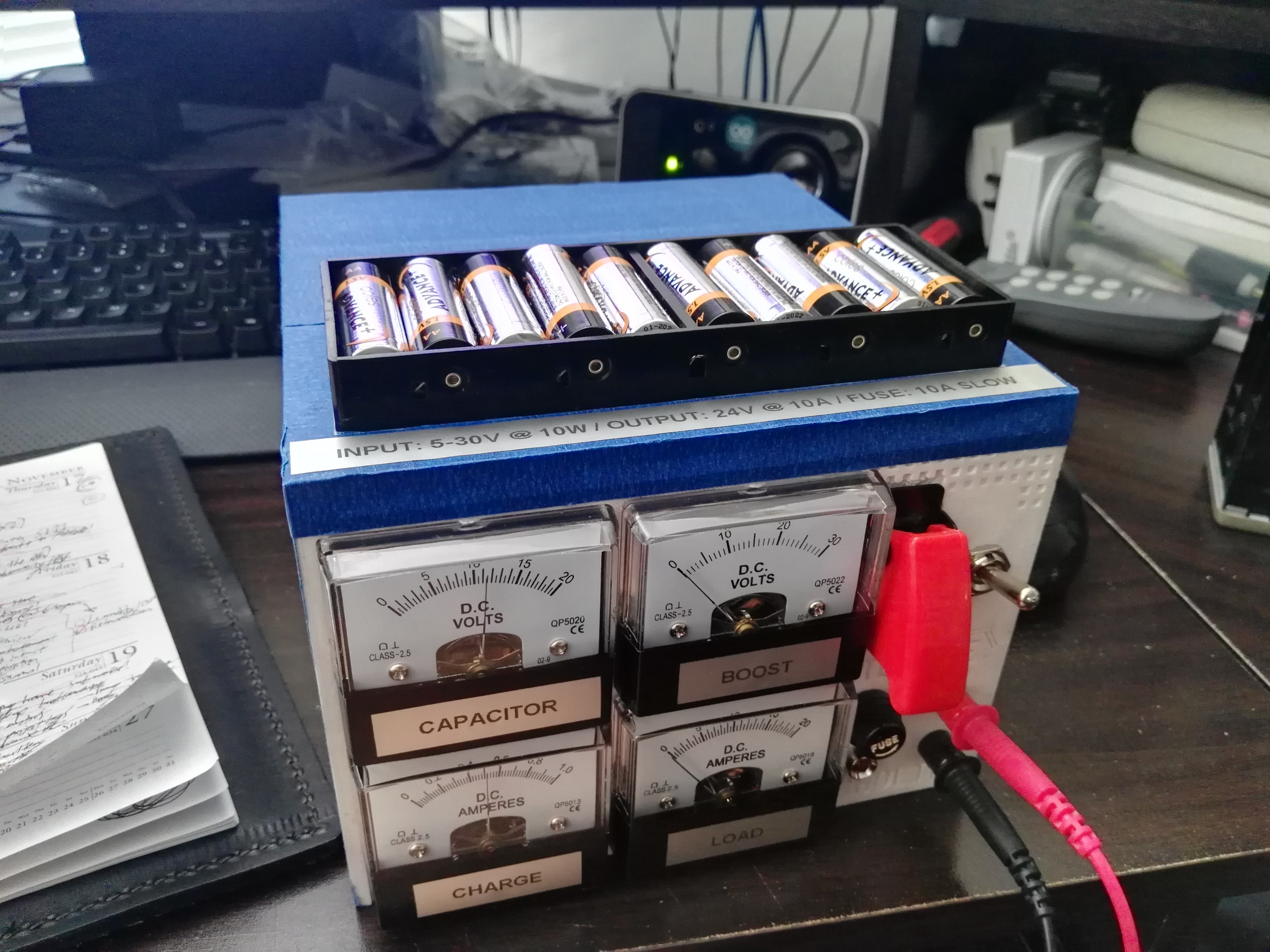
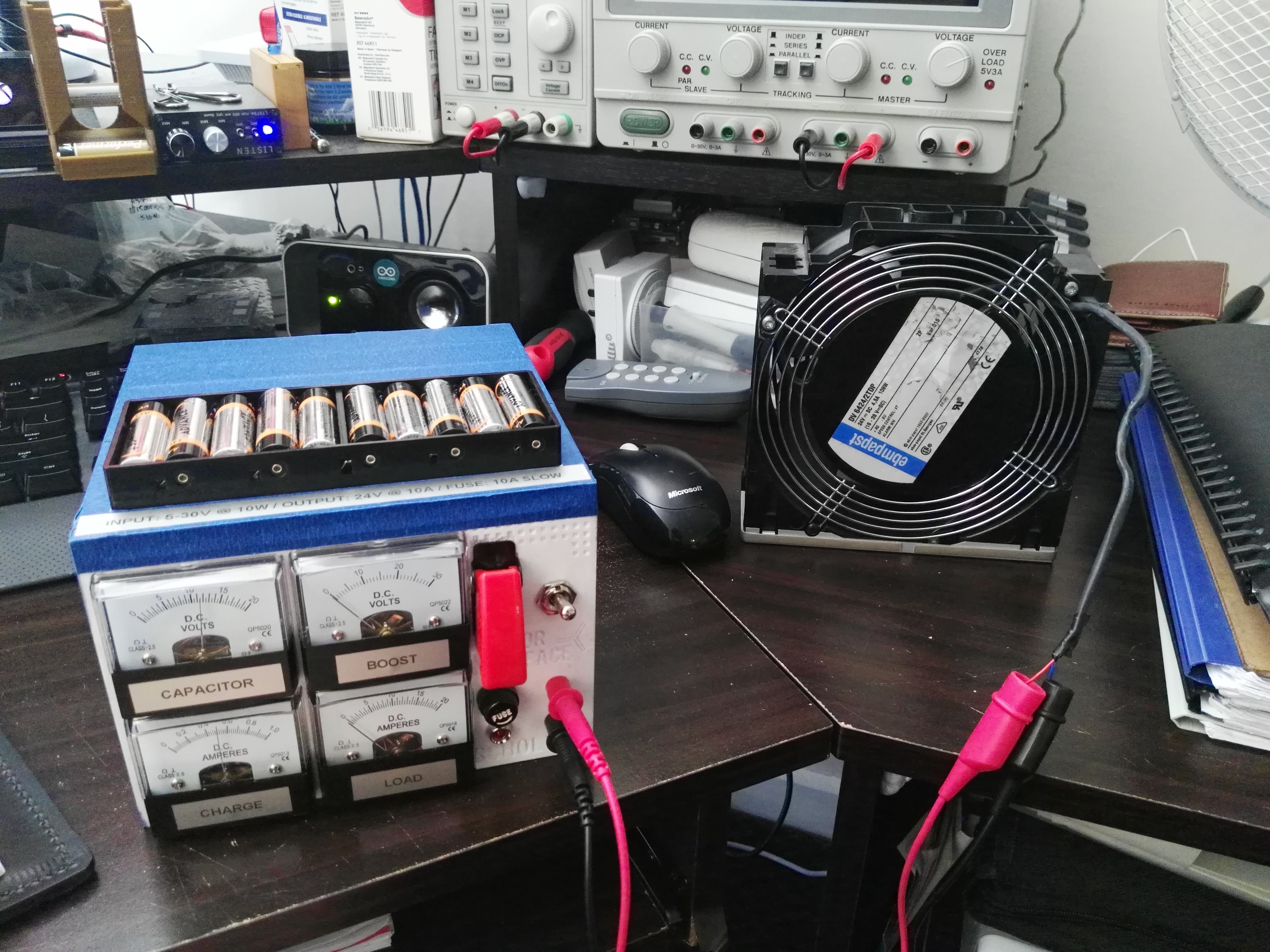
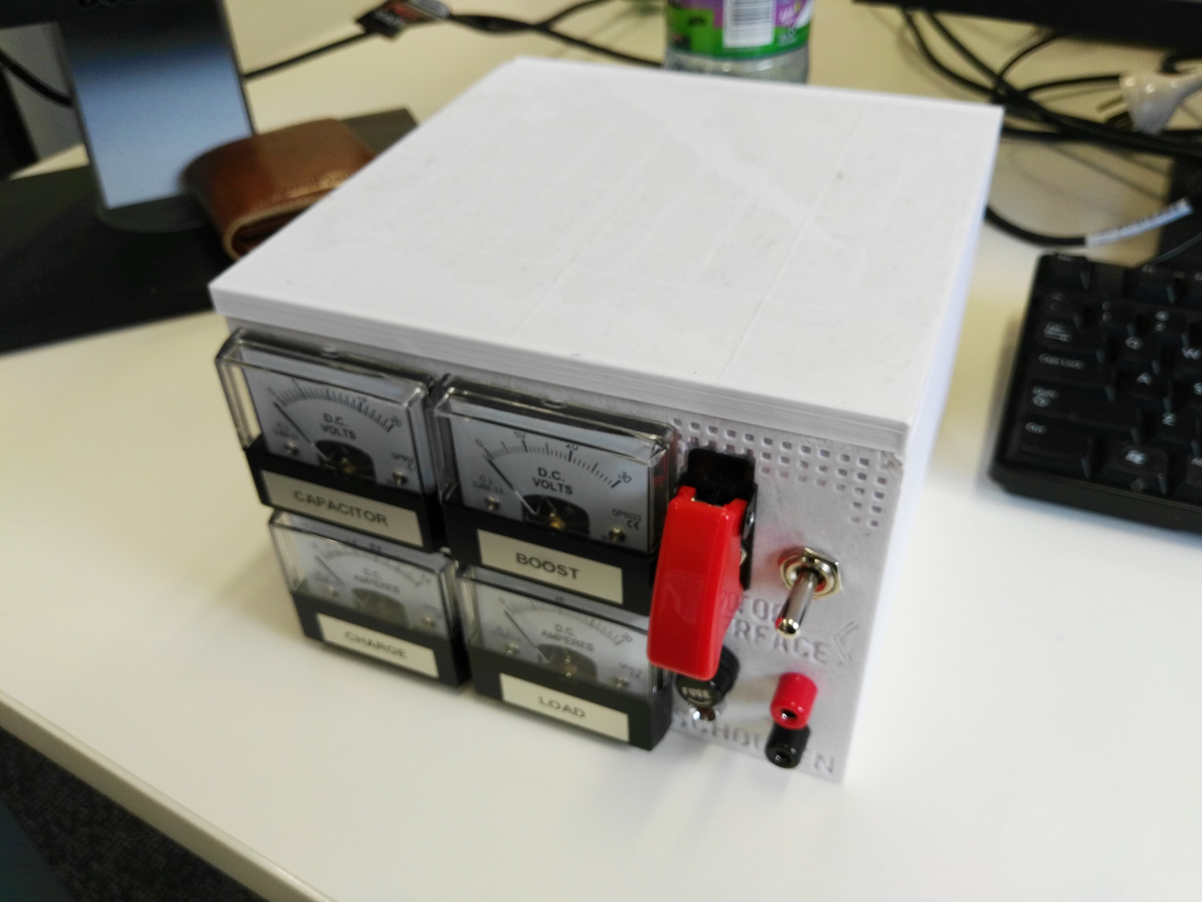
    It's finally here! After the buck converter replacement finally arrived I was able to complete the box:

    Here is a video of the super capacitors discharging into a 100W load:

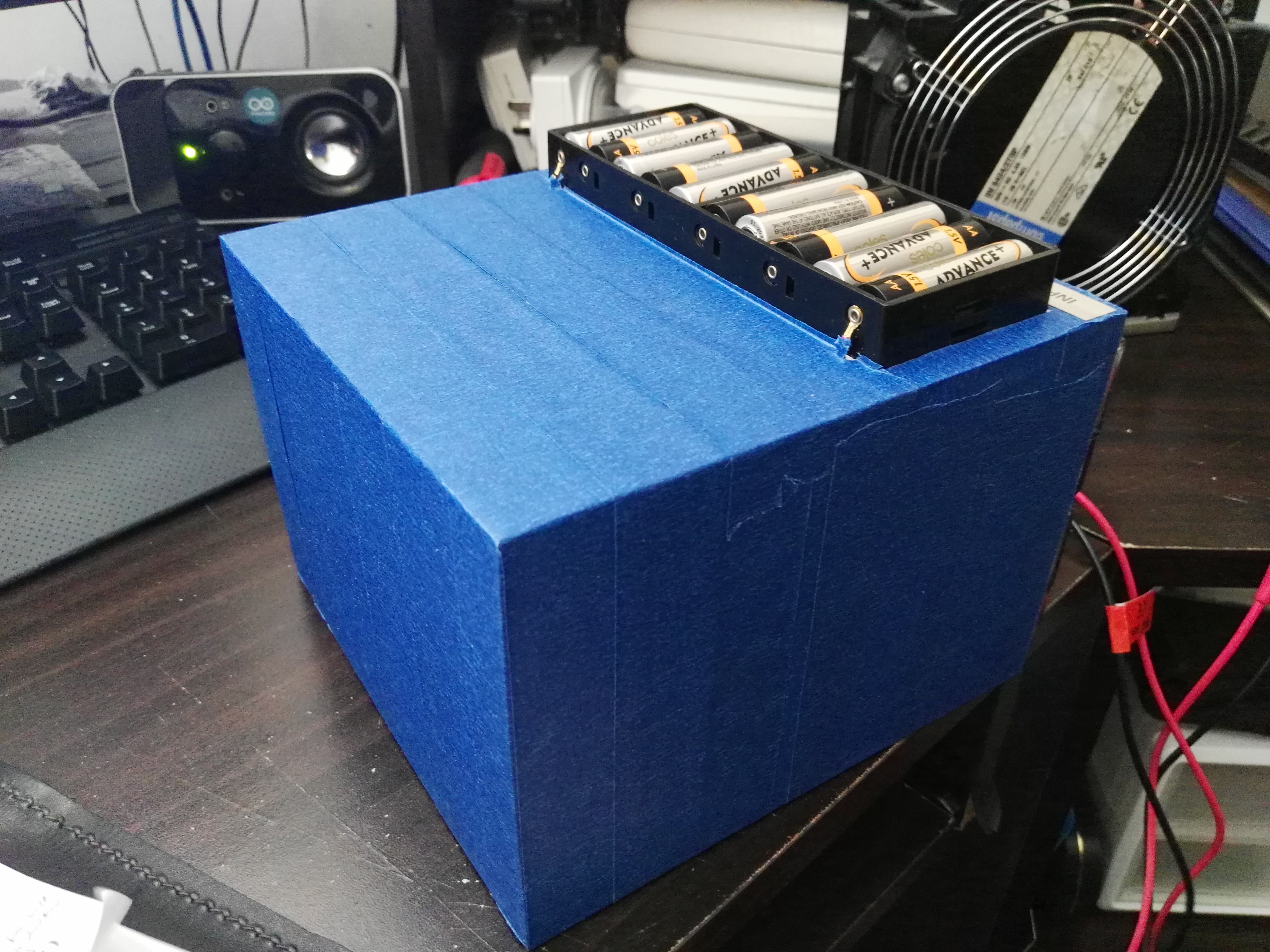
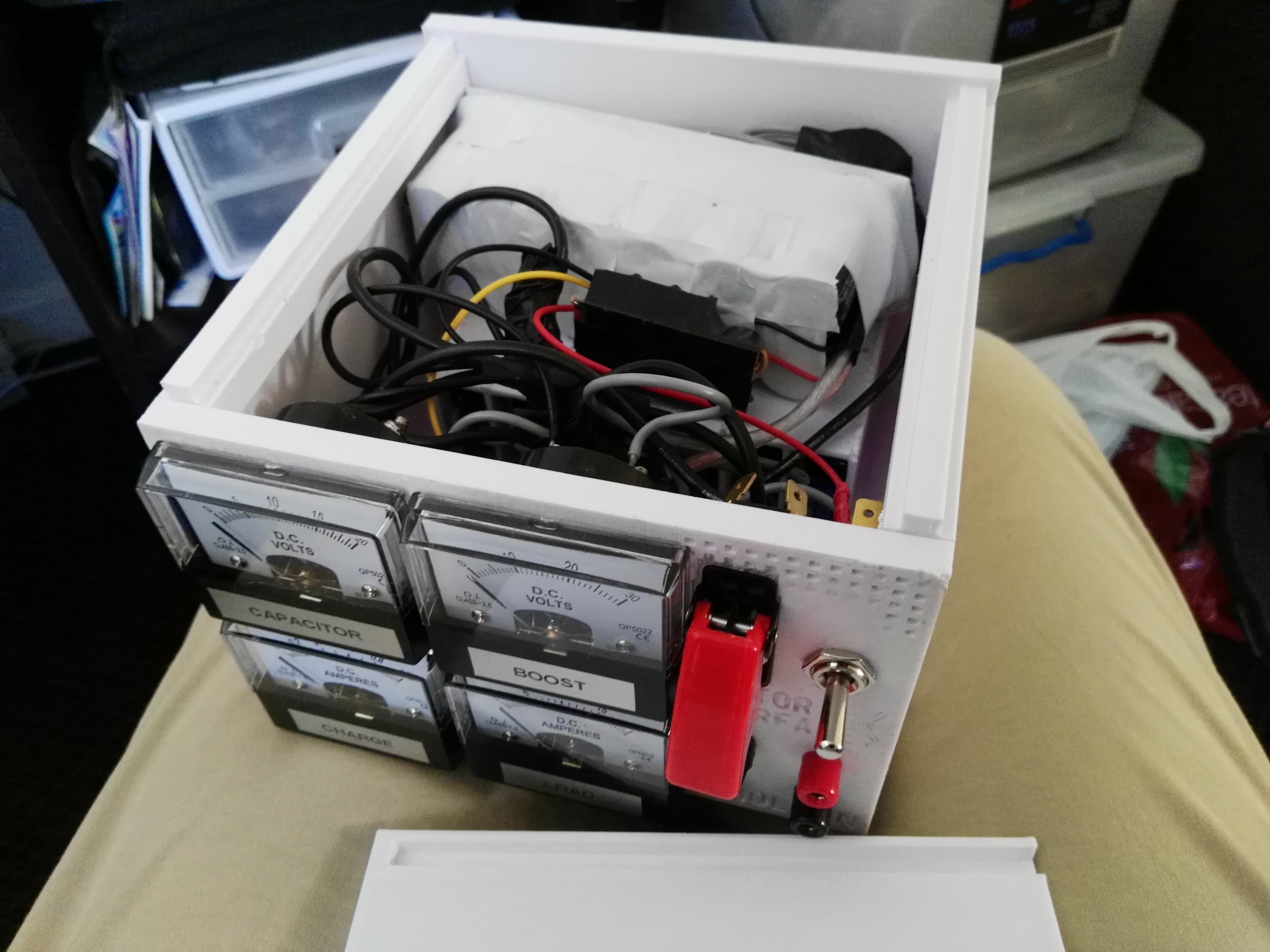
    Some pictures of just before I added the blue painters tape to spruce it up:

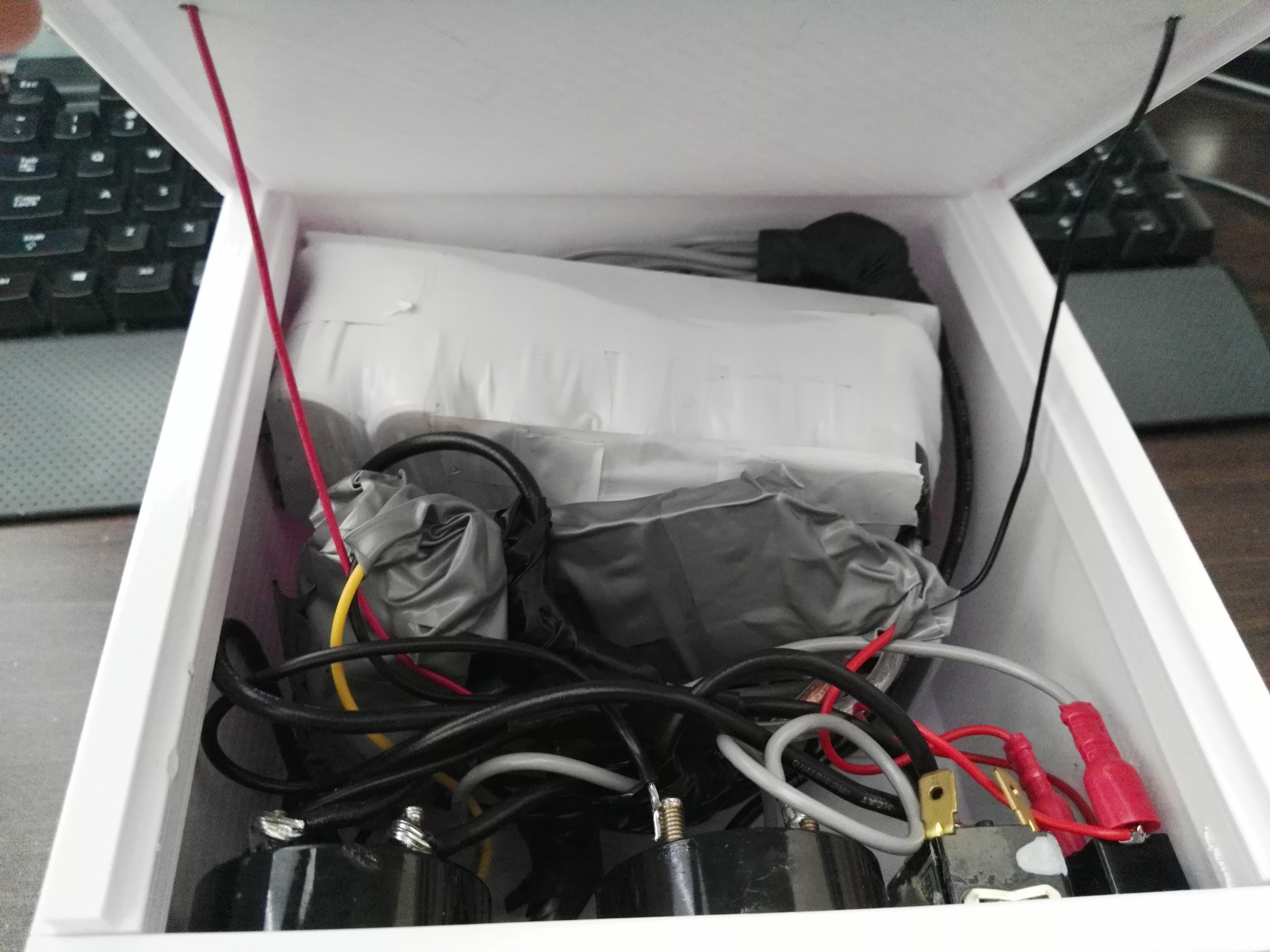
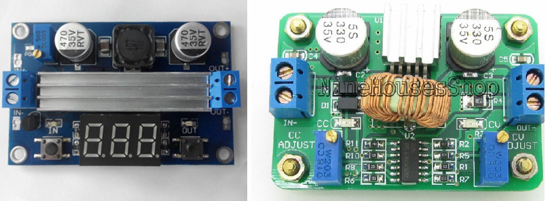
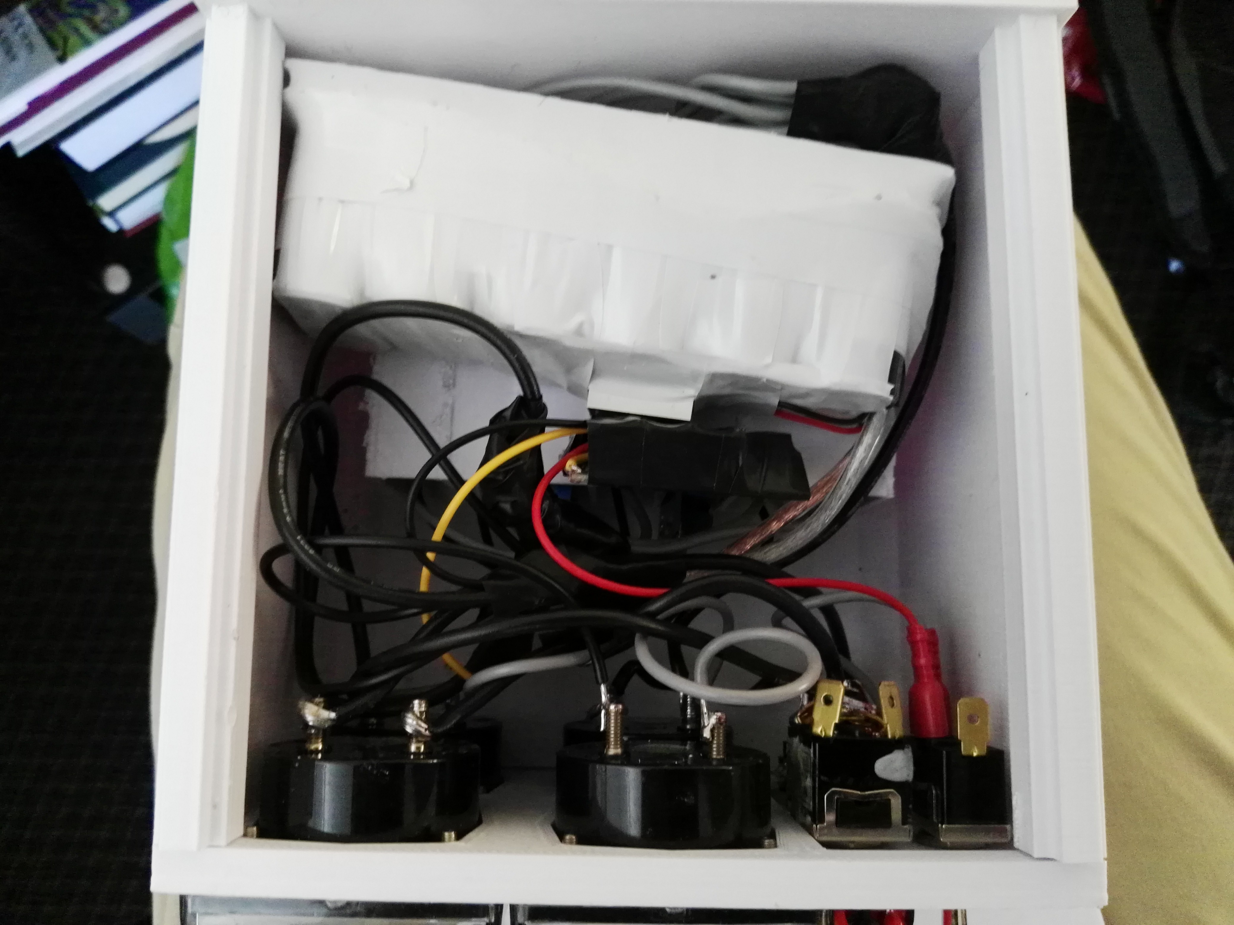
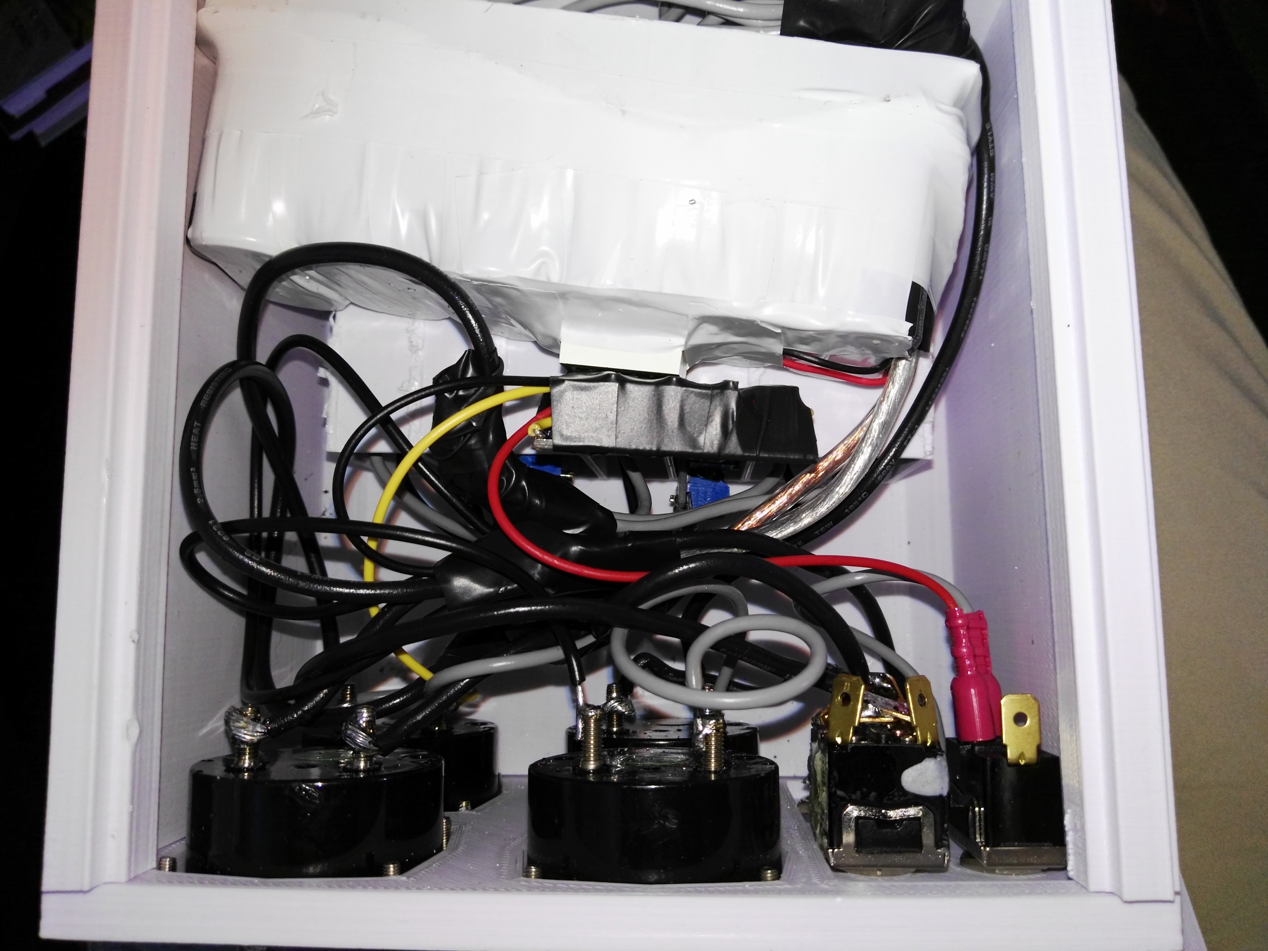
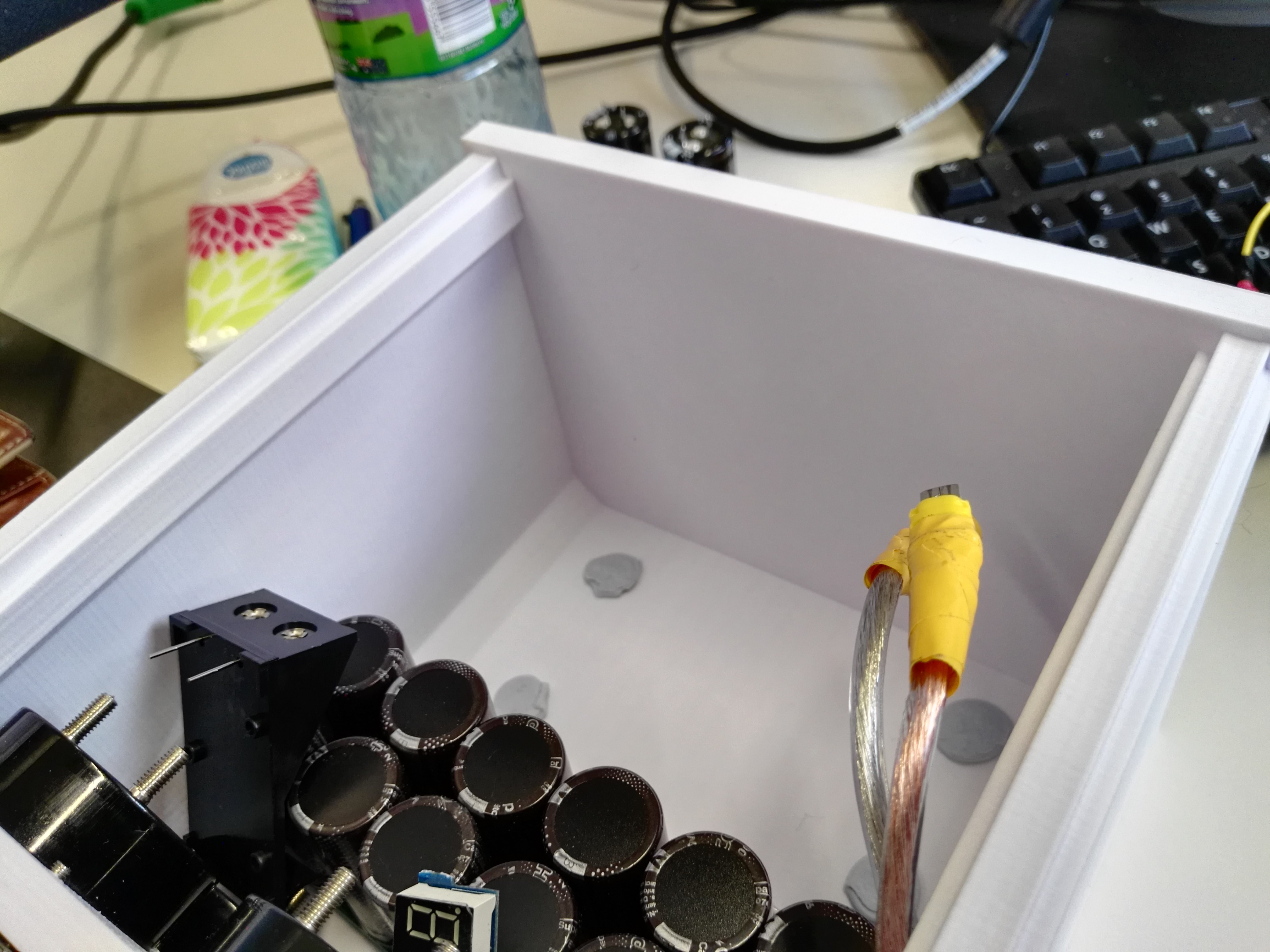
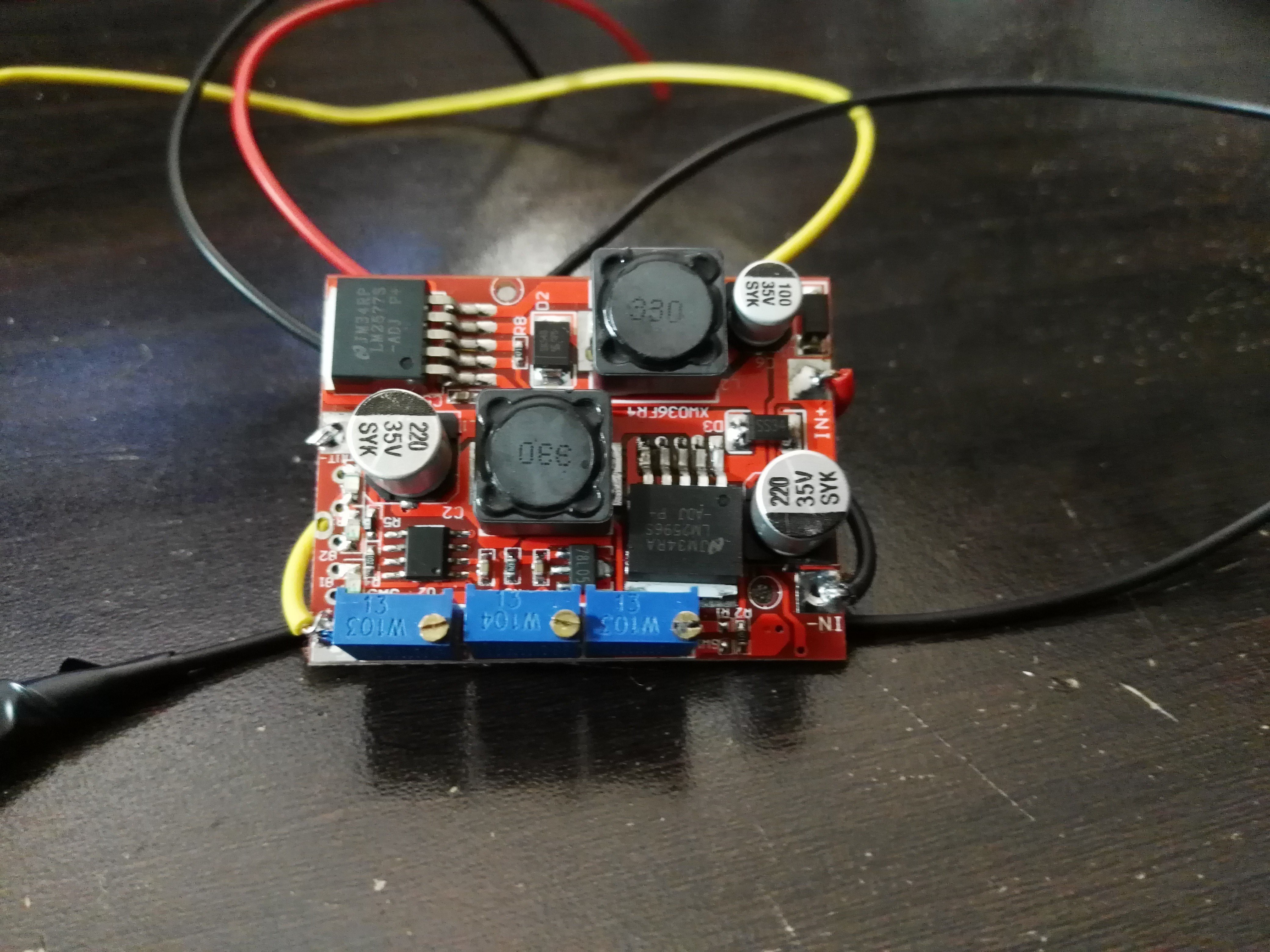
    You can see that the inside has become a disgusting mess, which is unfortunate, but I can safely say that there will be no unintentional shorts. The boost/buck converter utilised was a combination of one of the many boost converters that have been seen and another buck converter from eBay:

    These two converters in series act as the charging circuit, taking power from the batteries and storing it in the super capacitor bank.

    After testing the entire box half a dozen times (it takes nearly 15 minutes to charge), I am happy with the results and have decided to go ahead with the purchasing of an electric bicycle conversion kit.

    The only drawback to the entire system is its behaviour as the AA batteries begin to go flat. As the battery voltage drops, the buck/boost converter compensates by drawing more current, which then further reduces the voltage and greatly increasing the current. Eventually, the voltage drops to the point at which the boost/buck converter input voltage is too low and the capacitor charge current begins to drop off. Unfortunately, this is at the point where the battery voltage is about 4V, which for 10 AA batteries (15V nominal) is a huge drop due to internal resistance.

    Basically, the batteries will heat up drastically to tell you when they are "flat".

  • It works! Sort of!

    David Scholten10/30/2016 at 05:02 0 comments

    Many compromises were made in the name of convenience

    Power ratings, wireless relays, complex logic between the switches, charging from the back EMF generation of the motor - These things are gone. Once you sit down in a lab with only the parts you have, the tools you have and limited time, you need to choose what you are actually going to use this box for.

    • The number of boost converters has been reduced from 10 to 7.
    • There is no wireless control.
    • The switches now directly control the current (no high current relays)
    • The boost holder has been physically cut in half to allow for more room.

    To summarise what's left:

    Power flows from the batteries (5-10 AAs) and into the boost/buck converter that then chargers the supercapacitors with a constant 0.6-0.8A. These banks of super caps are balanced by two parallel balance boards. The output of these caps then goes to 7 boost converters connected in parallel that then connects to the output. Of course, all of the switches and panel meters for displaying the status of everything important remain.

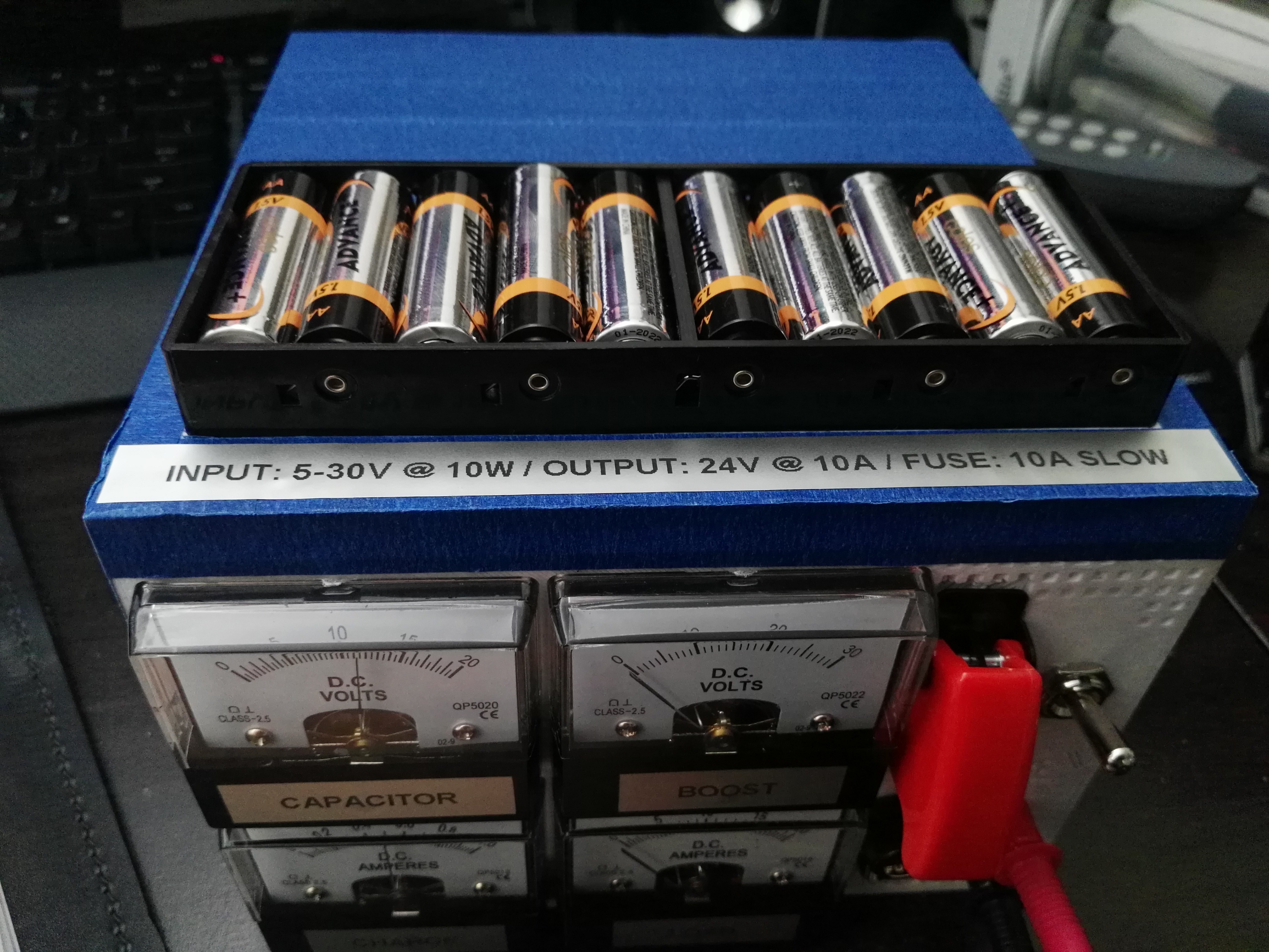
    On top we can see the wrapped super capacitor bank, which is sitting on the 7 boost converters in the 3d printed holder. The boost/buck converter is floating freely wrapped in black tape:

    Problems!

    • I made a mistake with some grounding assumptions and the charging circuit is well and truly dead. However, it did its job successfully for quite a while. Another board is on the way!
    • Due to my rushed solder job (don't judge) I overheated the contacts of 3/4 of the panel meters and internally de-soldered contacts. Luckily, when I paid my parents a visit, Dad suggested and carried out a fix that he was very familiar with (these panels are almost $20AUD each).
    • I completely ran out of space due to the magnitude of the cables coming out of the 7 boost converters, which simply took too much room. As you can see, half of the box is filled with panel equipment and vacant space criss-crossed with wires. I believe I will have to make the battery mount external (glue it to the top lid). This is okay though as then I don't have to open the box again (there is leaded solder everywhere).


  • Box has Been Printed

    David Scholten10/22/2016 at 01:48 0 comments

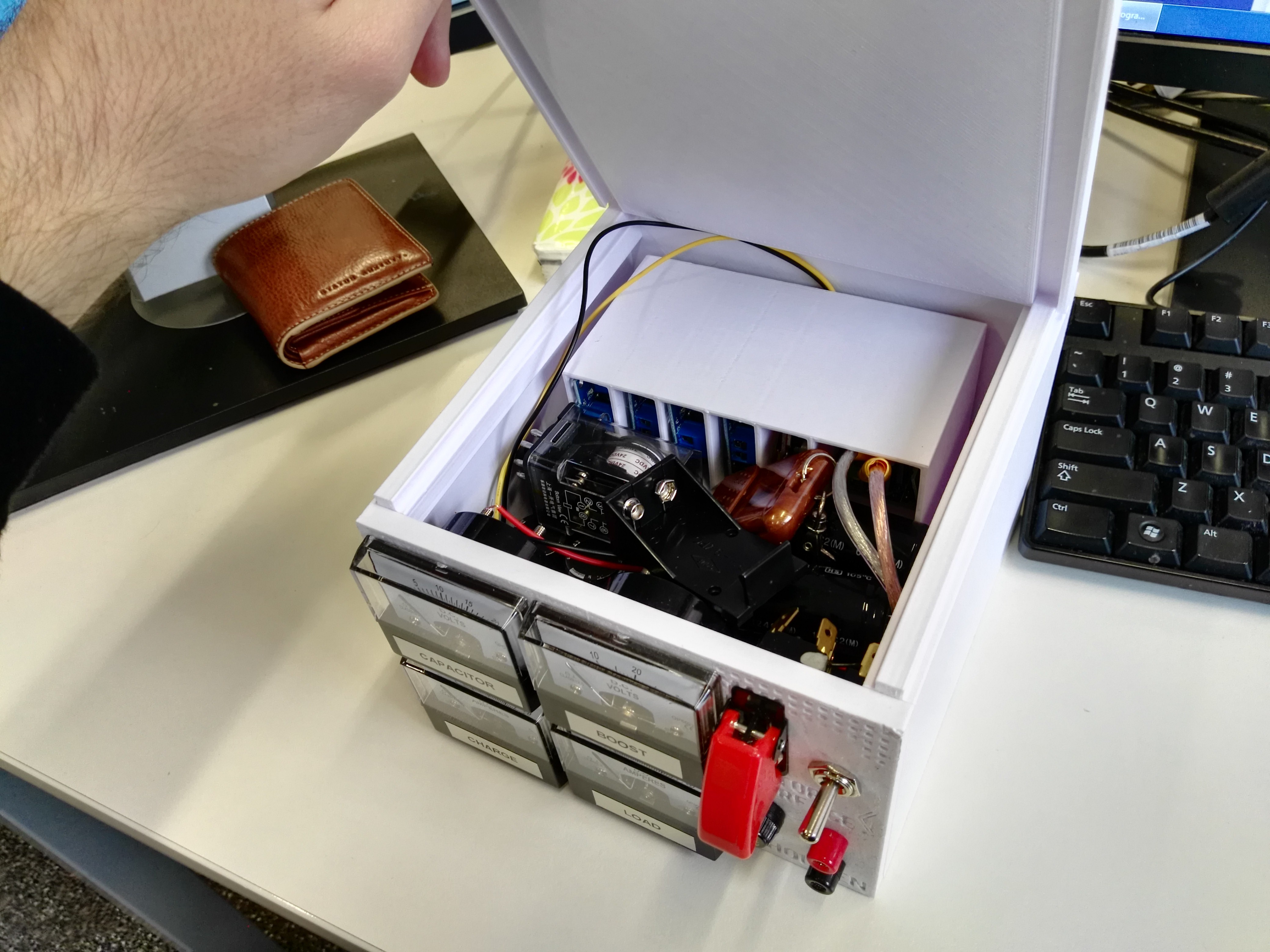
    Taking a total of about 24 hours of print time, the rest of the box has been printed:

    Nothing has been electrically connected yet and it's not going to win any award for energy-to-weight ratios:

    The top lid:

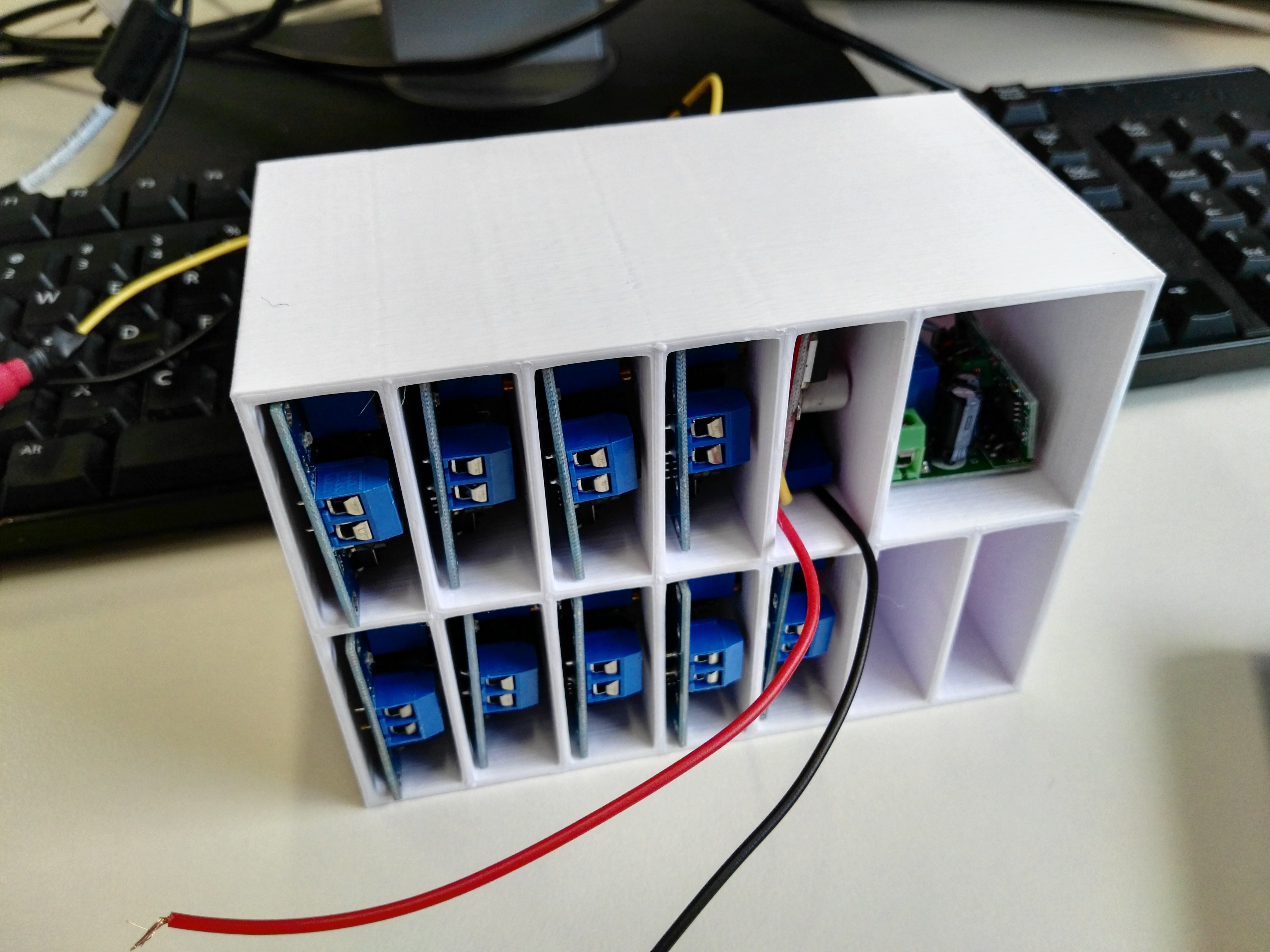
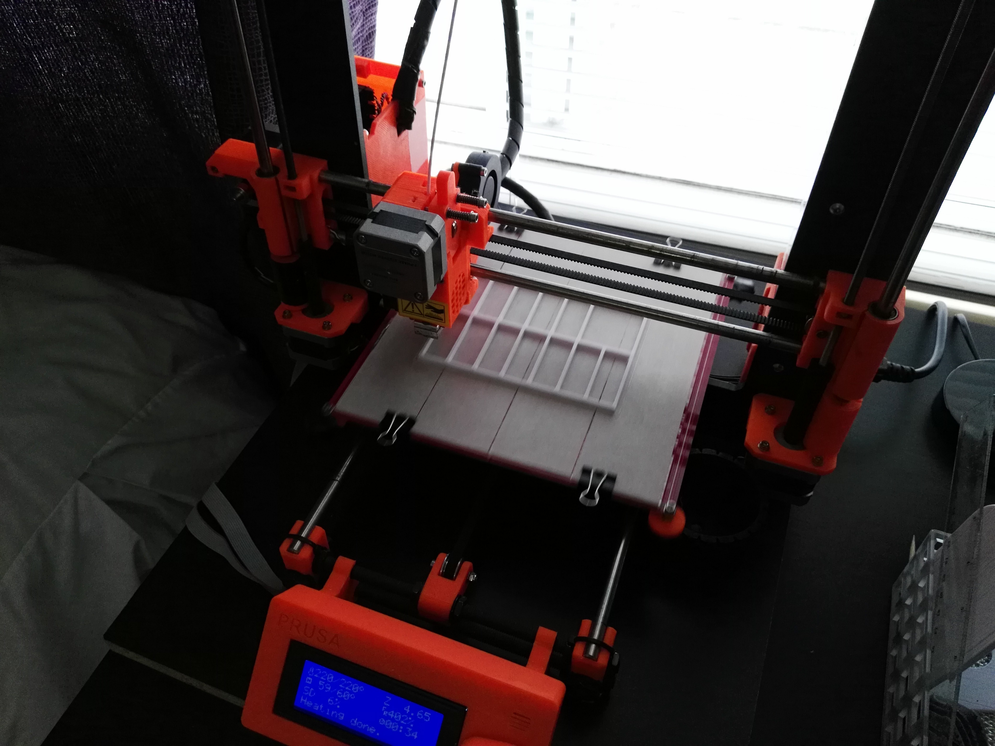
    The "bookshelf" where all of the module boards are stored:

    Where the bookshelf lives:

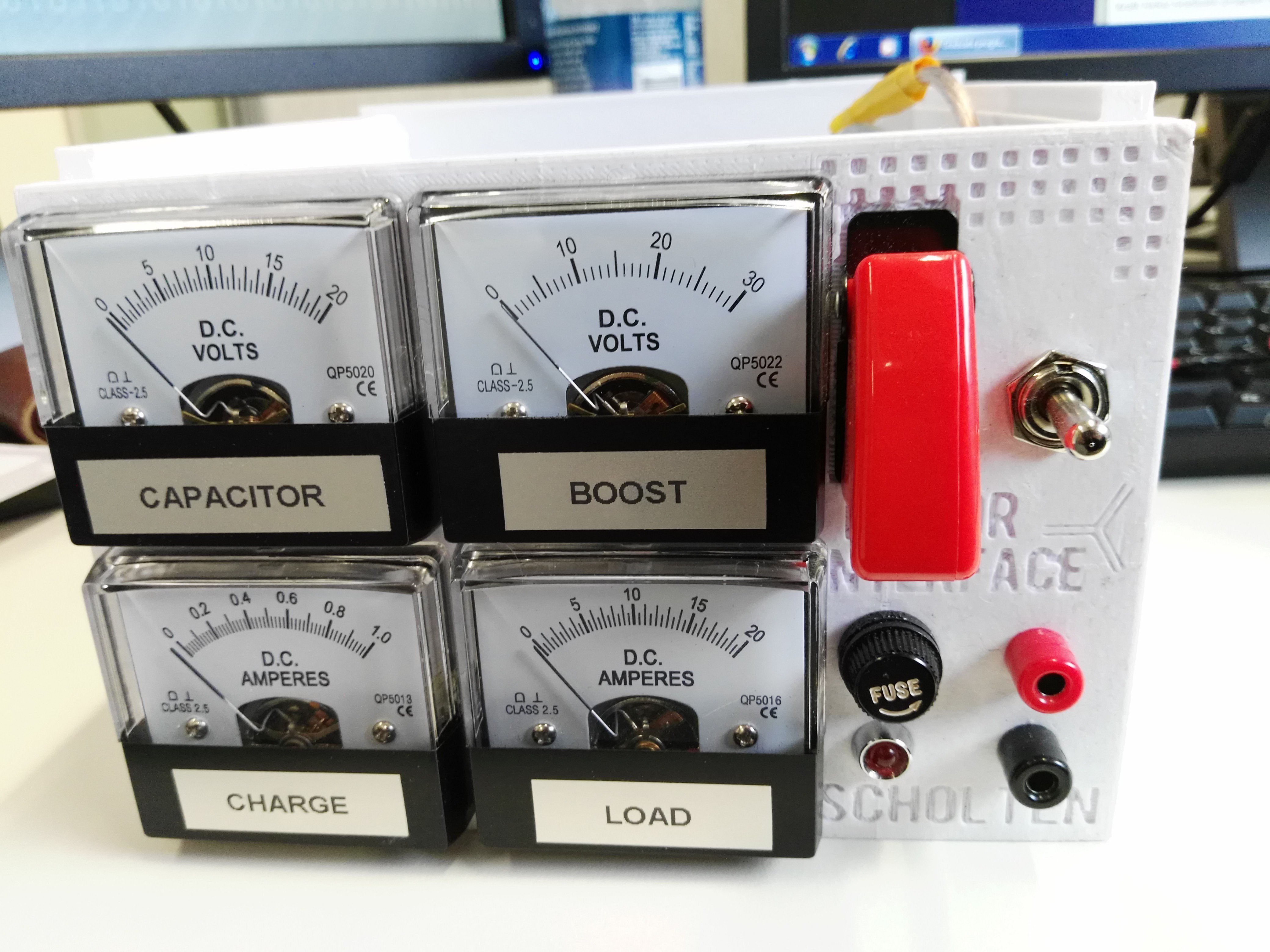
    Any a nice close up of the newly labelled front panel:

    Something unexpected did occur though. Out of the 11 boost converters I had available, two of them did not function at all. As a result I've ordered another 4 from eBay (E.T.A. 1.5 weeks).
    I also managed to find an old bicycle that would do nicely with a cheap electric conversion.

    Not much else this week!

    Soon I hope to start finding the best way to harvest energy from the DC-link of a brushless motor controller, forcing it to pass generated power back from the motor.

  • Box Construction is Underway!

    David Scholten10/16/2016 at 02:13 0 comments

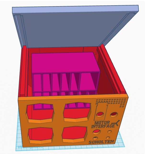
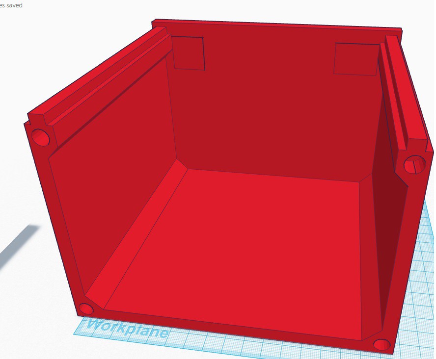
    Now that I have all the necessary components, I finished off the design of the box to house everything (using TinkerCad).

    First we have the base of the box:

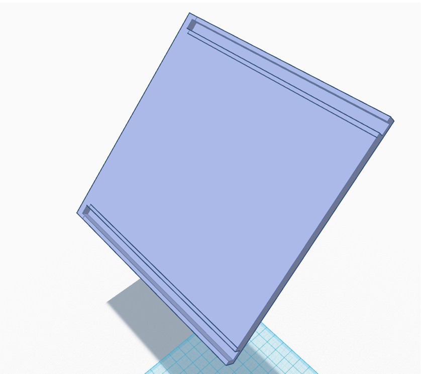
    Next, the lid:

    All together this looks something like this with the existing front panel I designed earlier:

    You may notice the purple object within:

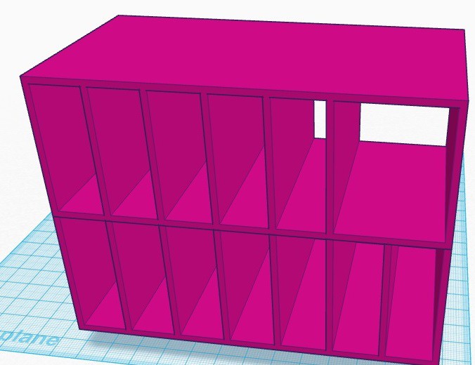
    This "book shelf" is to hold all of the boost converters (plus the charger and wireless relay board) in an organised fashion as visualised below:

    Now I just need to wait for the box to magically apparate in my room:

    Nothing technical here today! However, I did make the (lazy) decision to have no other ports or battery insert slots. This means that any batteries will be stored internally and will require easy access through the top panel lid.

    So, either:

    A - The batteries are internal.

    OR

    B - Power is drawn from the output port (i.e. generated from the motor of a bicycle).

    Expect to see the final external box soon!

  • Boost Converter Testing

    David Scholten10/10/2016 at 13:53 0 comments

    The boost converters have arrived!

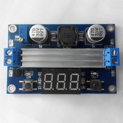
    I ordered 12 of the following:

    "DC-DC 100W 3-35V to 3.5-35V Boost Step-up Modules Power Supply LED Voltmeter New"

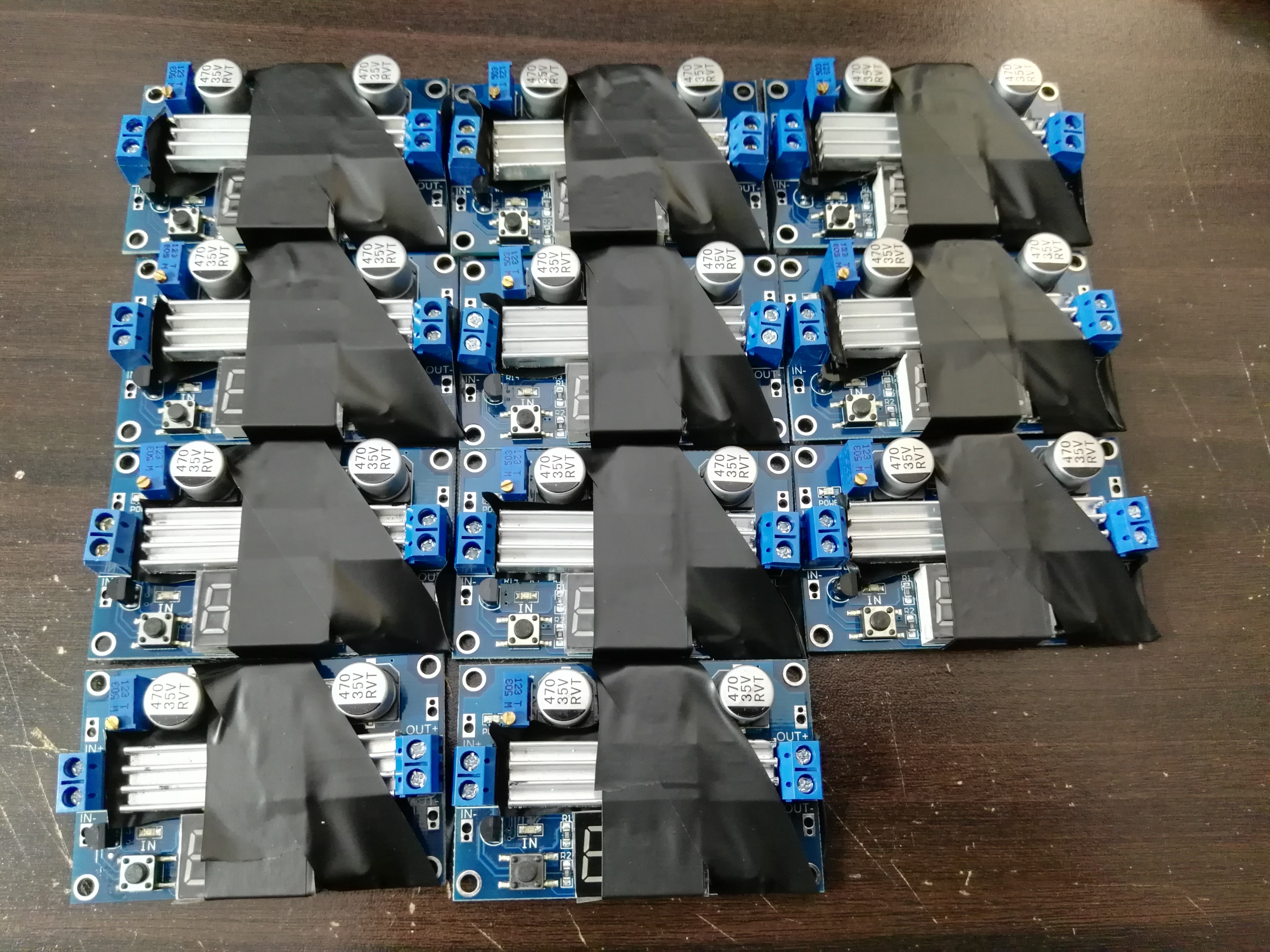
    Unfortunately, the heat sink that goes over both the output diode and the main switching transistor does not sit level (the semiconductor packages are at different heights). This meant that I needed to have separate heatsinks for each semiconductor! Fortunately, the heatsinks came unconnected with a tear away adhesive backing. All I needed to do was hacksaw each heatsink in half, peel off the backing and attach it to where it needed to go to fix the problem. The tape is for insurance.

    Boost converter Testing

    To test the 11 boost converters (may that 12th one rest in peace), I used a battery charger to apply a controllable load to one of the modules. The beautiful thing about the iCharger is that if the input source (the boost output) starts to decrease (voltage), it backs off the battery charging current. This effectively automatically tells me the current limit of the boost converter. As I wanted to boost a 0-16V super capacitor (4266J) to 24V @ 20A, I needed to know if 10 of these boost converters could fill these requirements. The worrying part is the necessary overrating due to the very high gain requirements as the capacitor voltage approaches zero. Below was what I measured for a single boost module:

    We can see the massive power drop off as the voltage gain increases to accommodate the dropping capacitor voltage. Now there are two concerns:

    • The capacitor current shouldn't exceed 60A for too long (capacitor is rated to 120A "peak" - whatever that could mean).
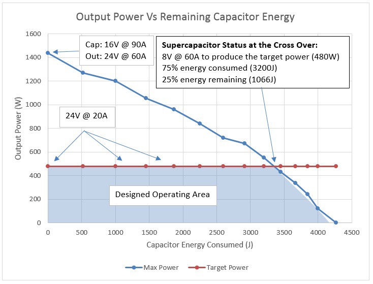
    • How much energy can be extracted from the capacitor before the 24V/20A/480W output rating can no longer be maintained?

    Lucky for us, Excel makes this easy to visualise:

    By looking at the capacitor state of charge through the remaining energy, we can see how the system will act over one discharge cycle. Seen in blue is the maximum possible power that can be drawn from the output at 24V. Seen in red is the rated power at the output that is ideally maintained regardless of the energy consumed from the capacitor. The overrating of the charged state capacitor is a bit extreme, but very much worth it for the extended operating area. Within the designed operating area (blue-filled region), the input current never exceed 60A, even if the 24V/480W output is maintained (though the input current will vary from 30A to 60A).

    However, something magical happens at the 75% (3300J) discharged point. Although the power drops below the rated 24V/480W due to boost converter limitations, even if it didn't, the capacitor current would have exceeded the 60A limit anyway. Effectively, these two limits have aligned by chance, not only maximising the capacitor energy that can be used (at 24V/480W), but automatically limiting the capacitor current within safe limits. The only protection for the entire system required is a slow blow 20A fuse at the output!

  • The Pieces Are Assembling

    David Scholten09/30/2016 at 10:35 0 comments

    Super capacitors are ready

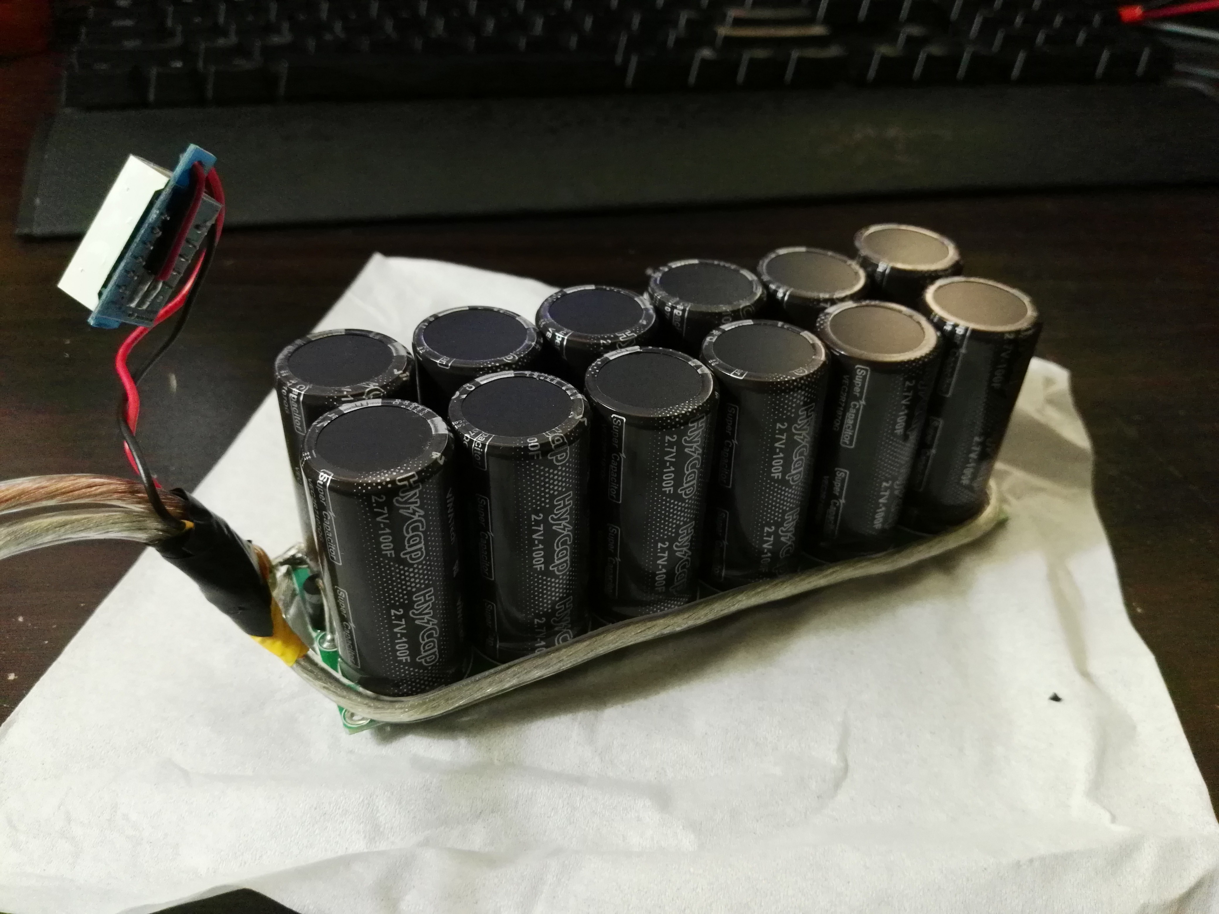
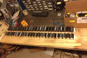
    I ended up with 12x 100F 2.7V super caps from my local Aztronics store. These things are rated for an "average" current of 30A each with a "peak" current of 60A. This is a total theoretical storage of 4374 joules. I connected them all together in two strings of six to form a 33.3F 16.2V capacitor with a current rating of 60A continuous.

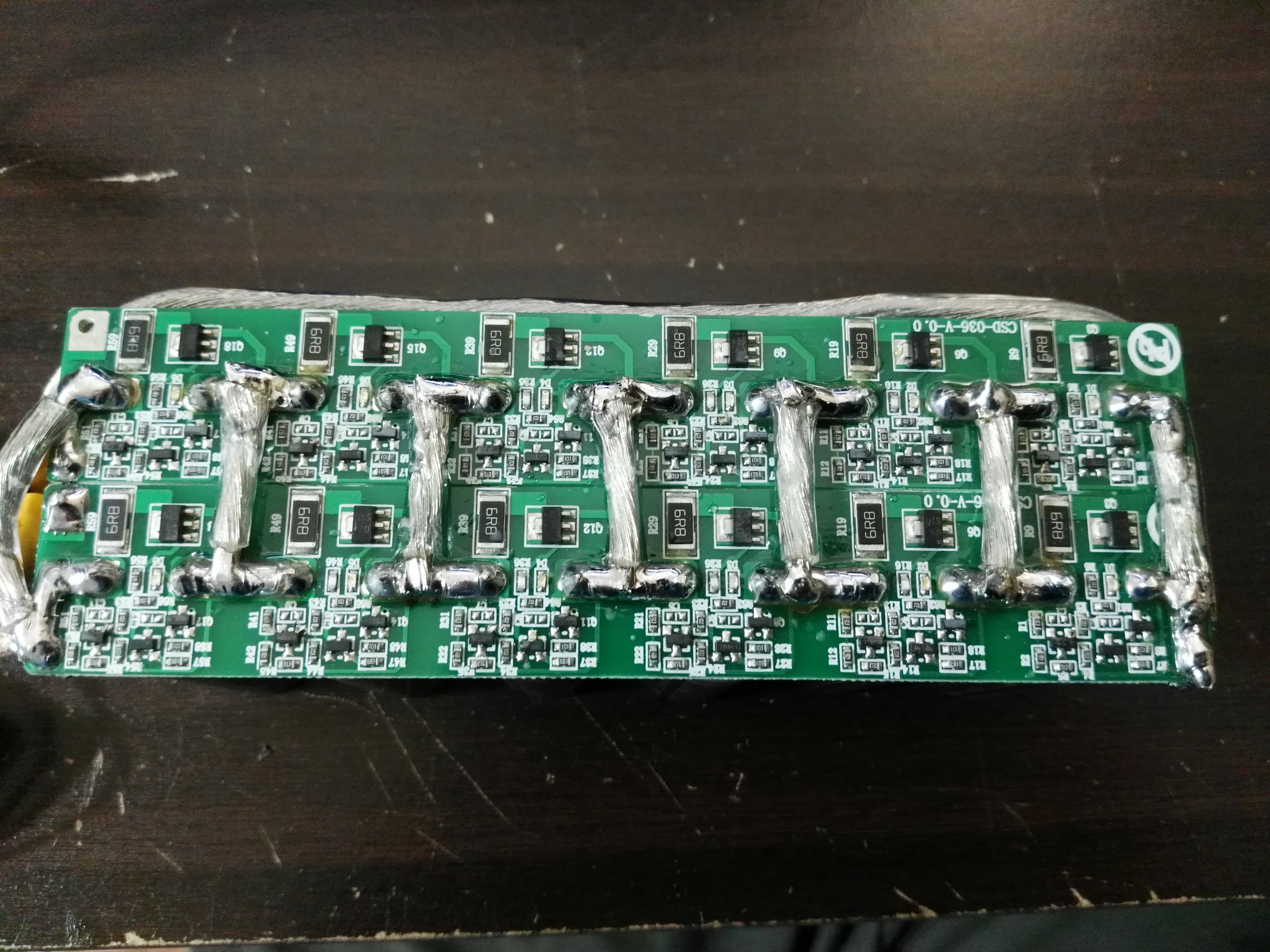
    To balance the super capacitors I used two boards that I found on eBay for a reasonable price. Each board will trigger at 2.65V and discharge at just under 0.4A. Importantly though, I connected each capacitor in the two strings in parallel (i.e. the whole thins is now six 200F 2.7V capacitors in series). This allows the balance circuits from each balance board to balance the capacitors from each side. The danger before this change was that if I charge at 800mA and one string takes on more than half the current then a single 400mA balance circuit is inadequate.

    Charging Circuit is working

    I grabbed a 0-30V to 0-30V boost-buck converter from eBay that is capable of delivering up to 3A to charge the super caps. At that rate it would take 3 minutes to charge the 4374 joule bank, but at the rate that can be safely balanced (0.8A) it will take 11.25 minutes minimum. Frustratingly, I cannot find little boost-buck converters like this that have any maximum power point tracking capability or a "constant power" mode. As the capacitors charge from a constant current the charging power increases proportionally with the capacitor voltage. This means I need to size a battery's power for the charging power needed near the completion of the capacitor charging.

    Other equipment that arrived

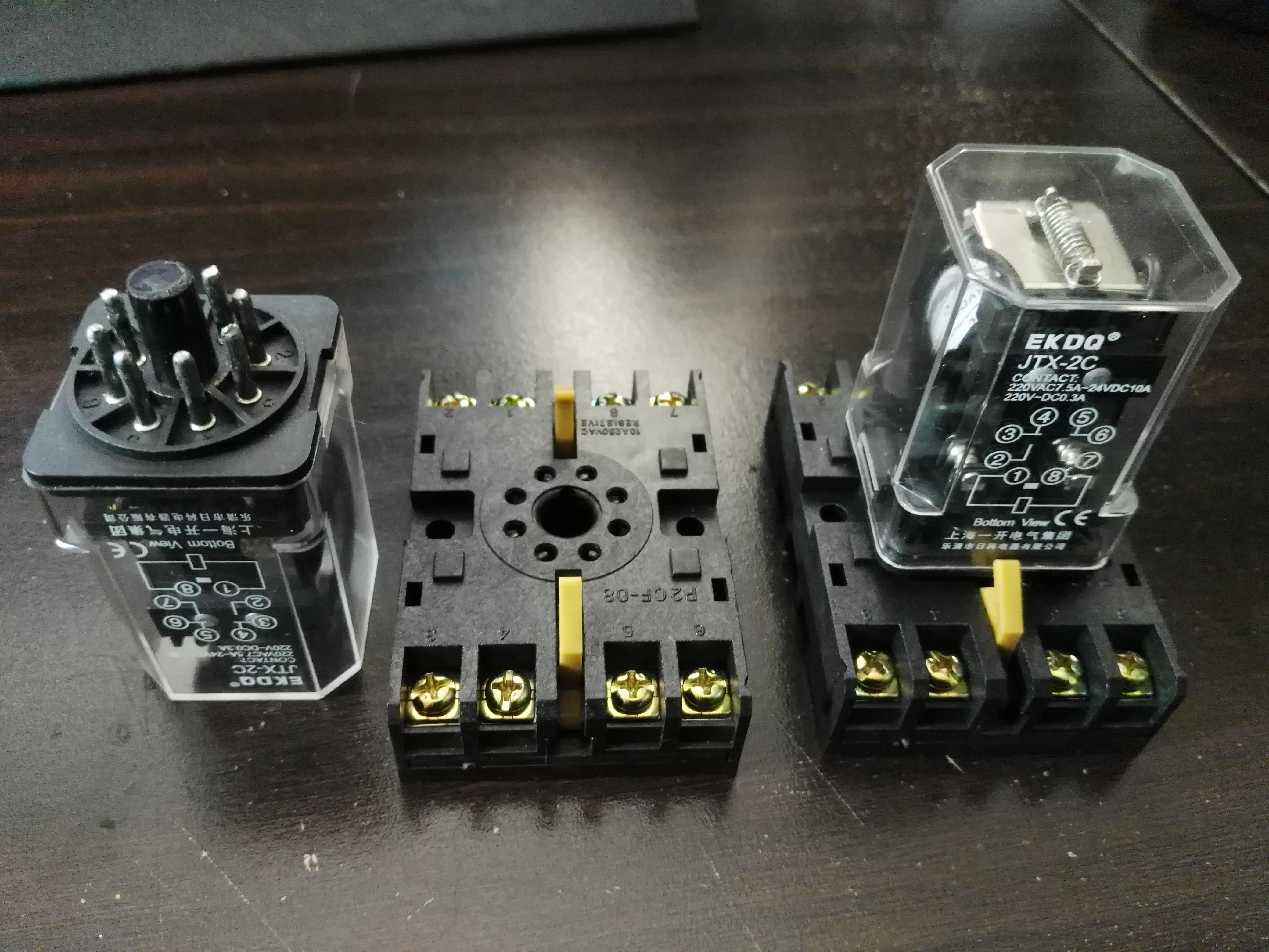
    Due to the high currents involved I thought it would be best if a heavy duty relay or two was in charge of switching the output on/off. As this box is supposed to be resilient, it would be best if I only had to replace relays and not mounted switches. These relays from eBay have a footprint I have never before seen and look eerily like vacuum tubes.

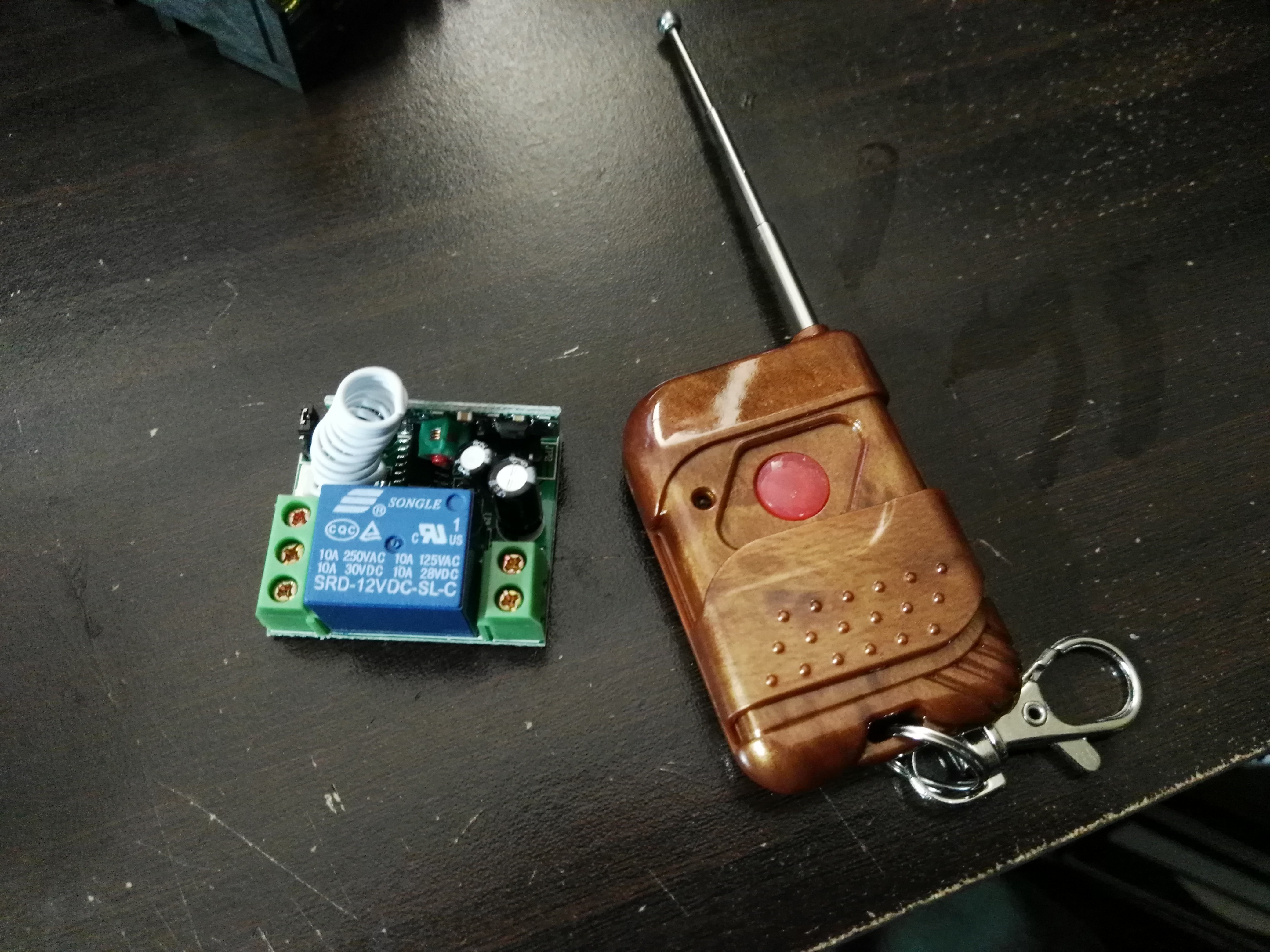
    This leads to the next great features of using relays which is controllability. Now I can use standard wireless switches to also power on/off the outputs of the box. This will be VERY useful if I am powering something dangerous in the middle of nowhere (rail gun?) and want to momentarily turn it on from a great distance. This little wireless module can toggle between momentary mode and latch mode.

    Next update:

    I have ordered 12x 50-100W boost converters from eBay to regulate the output of the super capacitor bank. Boost converters are ESPECIALLY handy when paralleling them as their outputs are through a diode. In addition, if the load is too great then the output voltage basically just drops as the boost converters begin to approximate a single diode. The best part about cheap low powered boost converters in parallel rather than a single high power boost converter is that the cheap ones are overrated and will quickly overheat. This is perfect for a pulsed power application as this means the cheap boost converters will provide more power than they should for their heat dissipation capabilities, but without the chance to overheat due to continuous operation!

View all 8 project logs

Enjoy this project?

Share

Discussions

Henry333 wrote 05/07/2024 at 17:40 point

A supercapacitor-based pulsed power supply for 24V DC applications would offer high power density, fast charging and discharging capabilities, and long cycle life compared to traditional batteries. It could be used in various applications such as energy harvesting, pulse lasers, electric vehicles, and backup power systems where rapid energy delivery and high power bursts are required.

  Are you sure? yes | no

Henry333 wrote 05/04/2024 at 13:08 point

Supercaps: Series connection for 24V, pick ones with high peak current.

DC-DC Converter: Regulates voltage down to 24V DC with good PWM.

Balancing Circuit: Keeps supercaps happy and dischargin' evenly.

Safety First! Proper charge/discharge circuits are a must.

Match Specs! Supercap voltage > 24V for headroom.

Pulse It Right! Design for your specific pulse duration/duty cycle.

  Are you sure? yes | no

Similar Projects

Does this project spark your interest?

Become a member to follow this project and never miss any updates