Rene
ReneOverview
The diagram below provides an overview of the module:

- Supports most monochrome parallel LCD display modules
- Remote console access to other modules
- Pilot notes and checklists
- CAN-bus debug view
- Multiple home-screens with user defined text and graphic widgets, linked to specified sensor parameters
Schematic and PCB
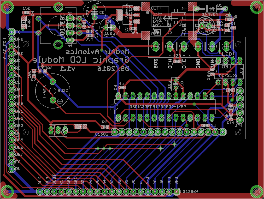
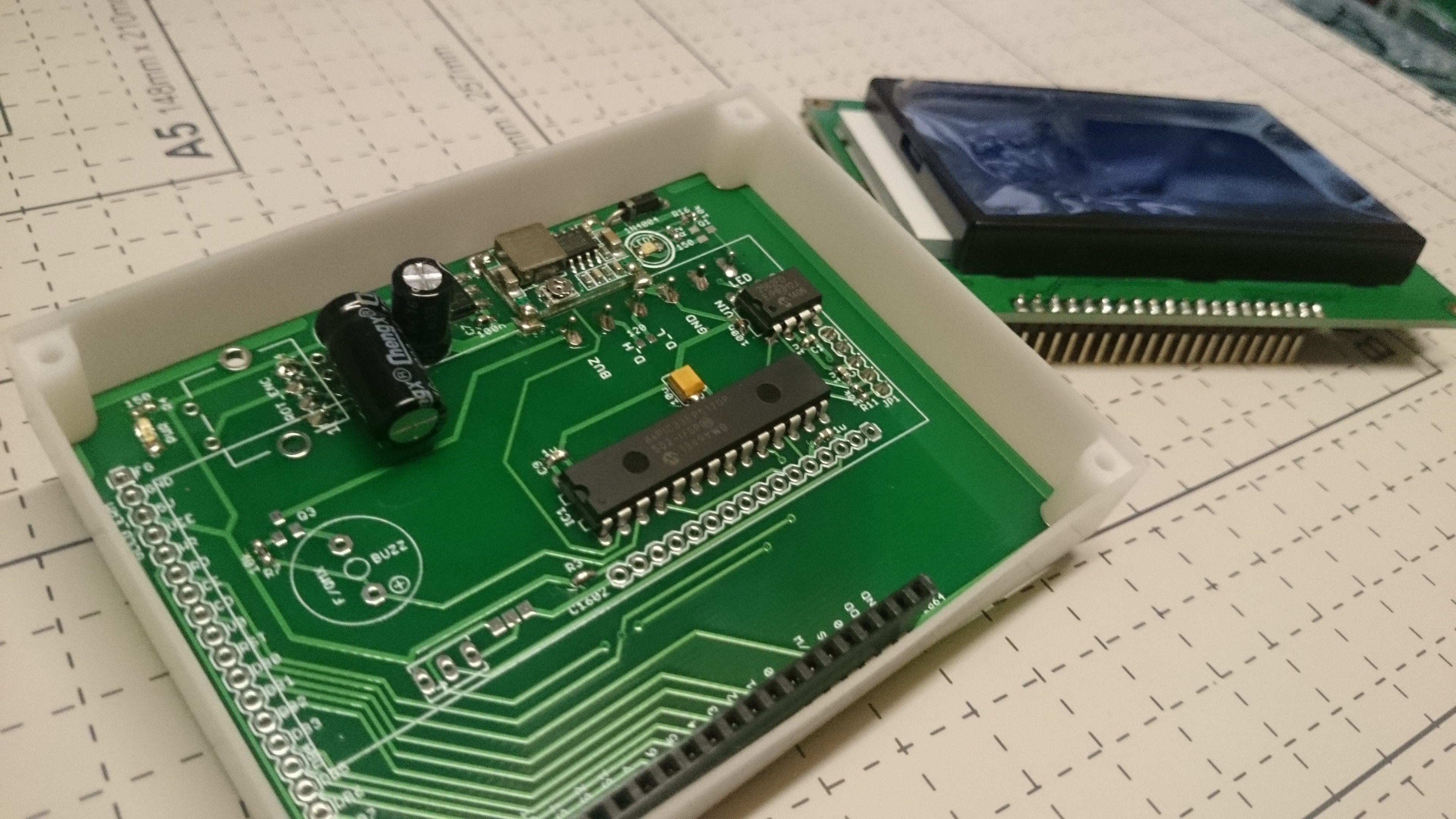
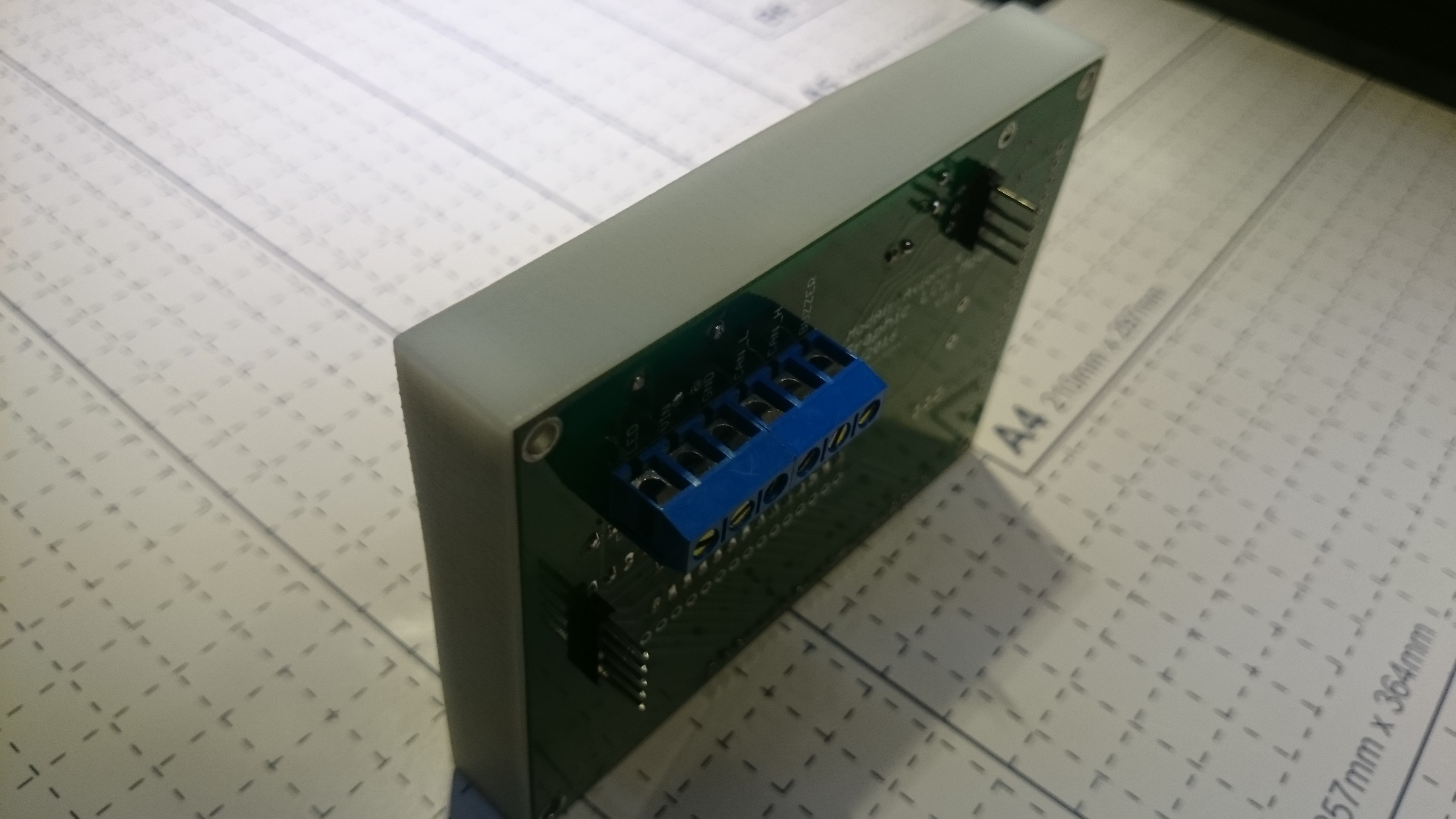
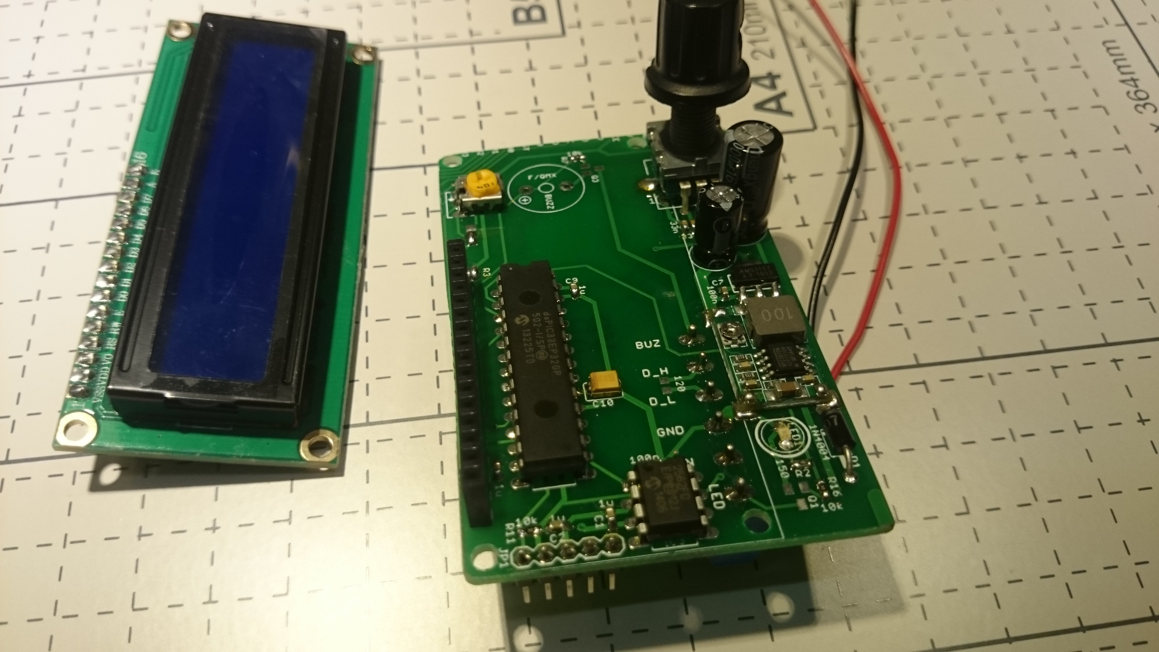
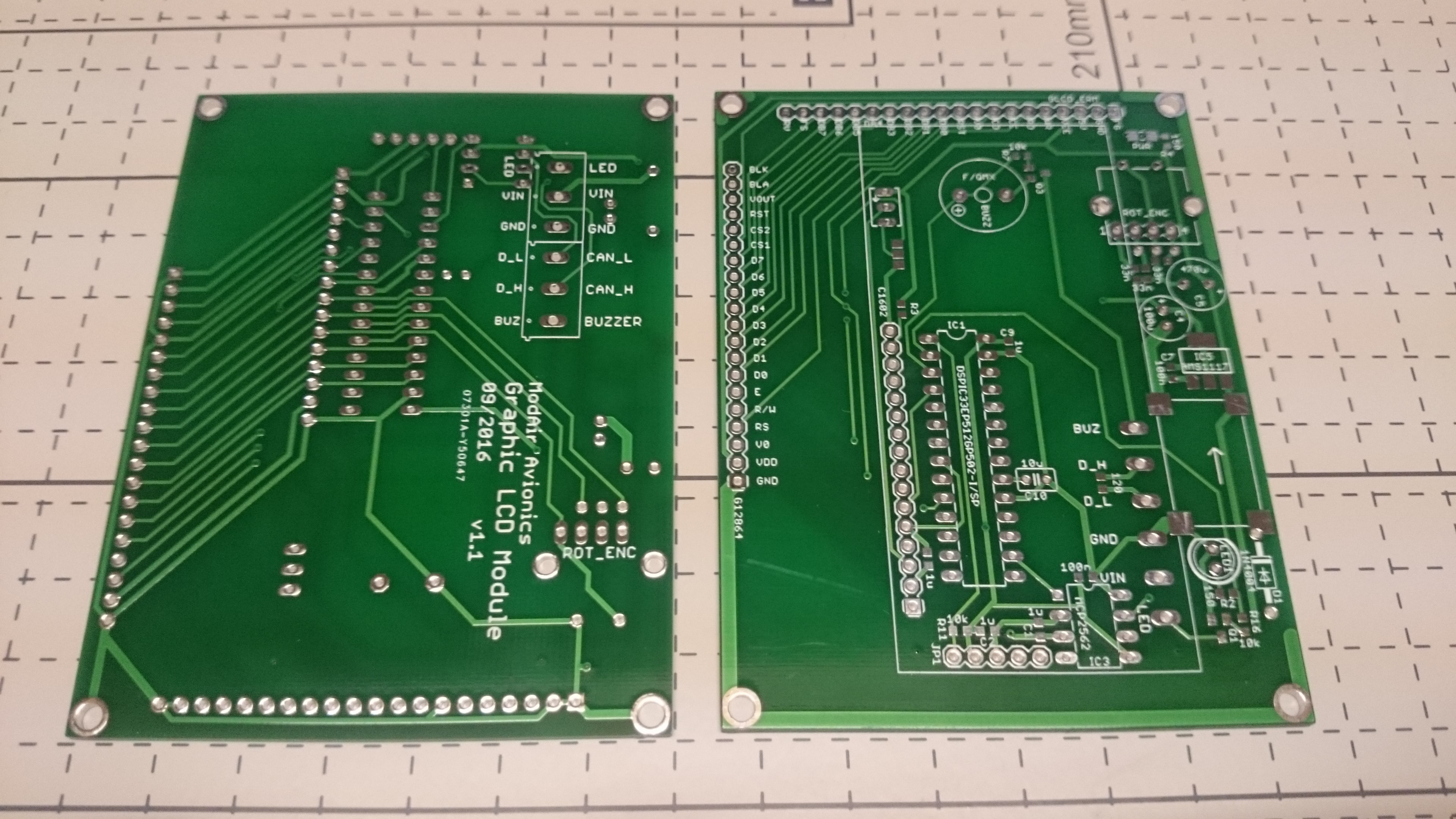
The schematic consists of a micro-controller, CAN transceiver, 5V switching regulator, 3.3V linear regulator, led, buzzer, rotary encoder interface, and three header pin rows for various LCD pin-outs.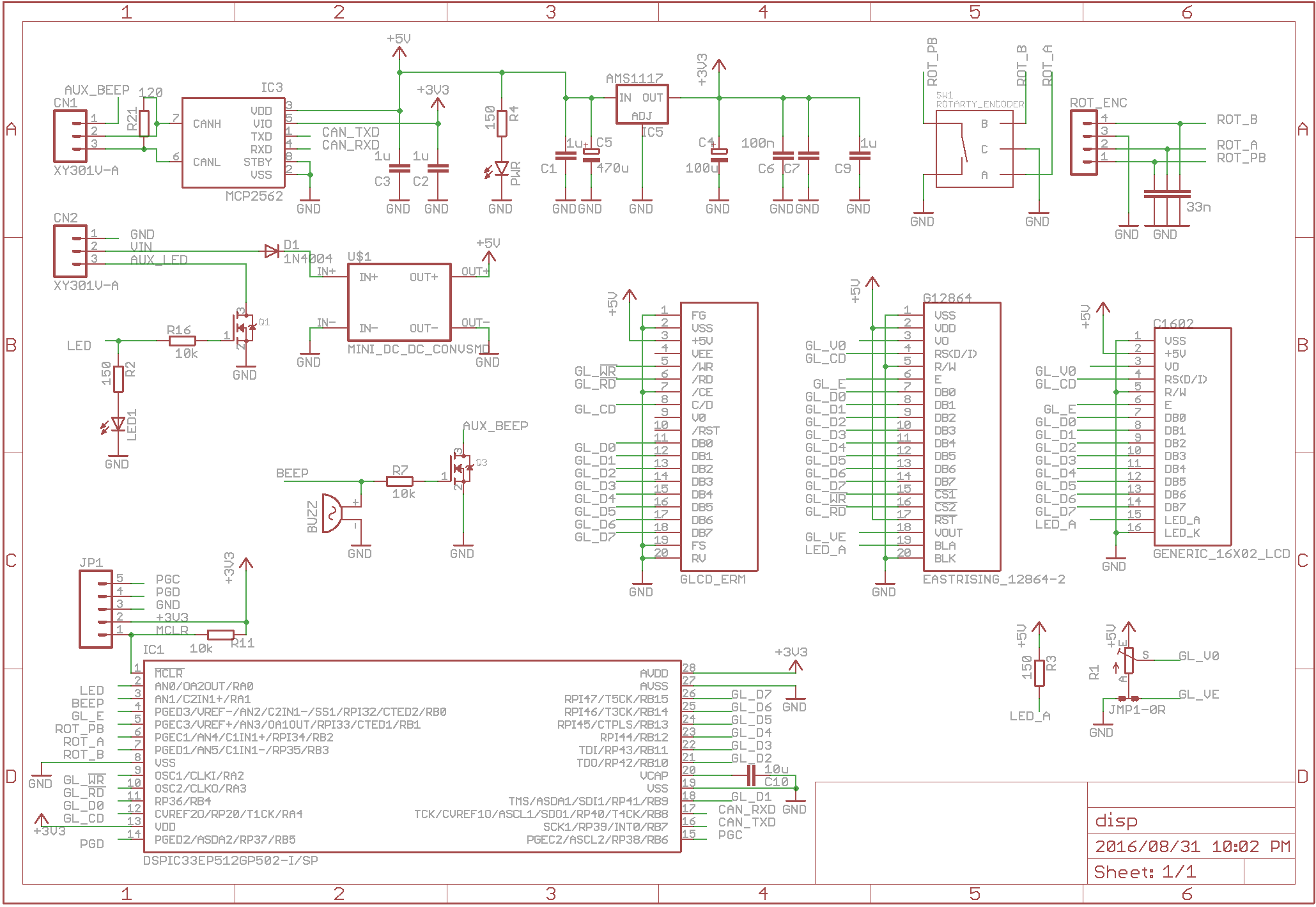 The PCB was designed to mechanically mate with some of the more common graphic and character LCDs. The following screens are recommended:
- Nelytech NT-G128641A. Black pixels on a grey background with white backlight, 128x64 dots (currently in my microlight)
- EastRising ERM12864FS-6. Black pixels on a grey background with white backlight, 128x64 dots (equivalent, not tested)
- AliExpress 1602. Dark pixels on yellow green background with green backlight, 2x16 characters (equivalent to the character one below, but STN positive instead of negative, not tested)
- AliExpress 5V 12864. Dark pixels on yellow green background with green backlight. 2.9 inch, 128x64 dots (equivalent to the one tested below, but STN positive instead of negative, not tested)
The following screens have been tested but are NOT recommended (not sunlight readable or discontinued):
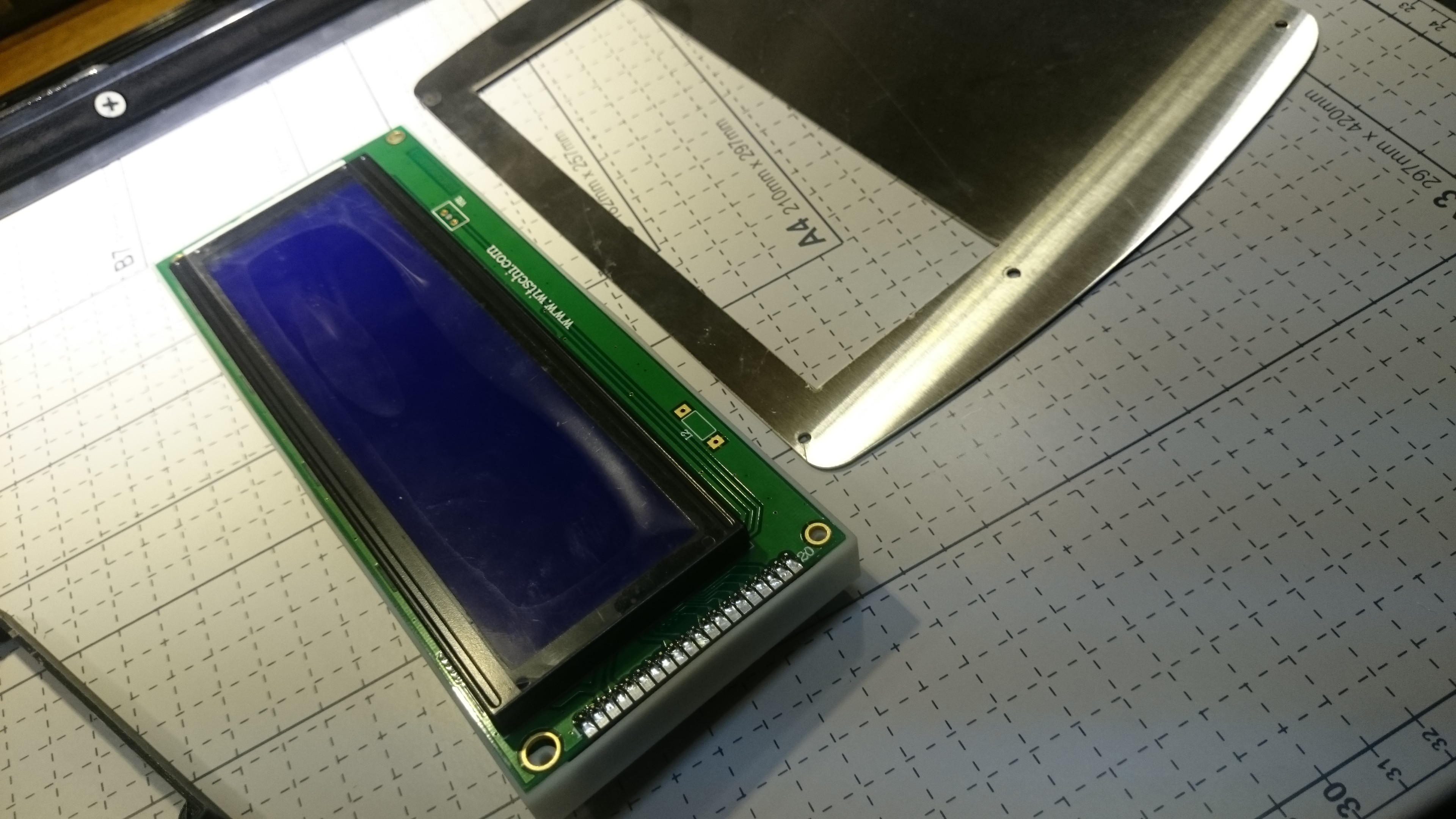
- Nelytech NT-G1286411A. White pixels on a blue background with blue backlight, 2.9 inch, 128x64 dots
- EastRising ERM25664SBS-1. White pixels on a blue background with blue backlight, 5.8 inch, 256x64 dots (discontinued, not easily sunlight readable)
- AliExpress 1602. White pixels on a blue background with blue backlight, 2x16 characters (white pixels are not sunlight readable)
- AliExpress 5V 12864. White pixels on a blue background with blue backlight, 2.9 inch, 128x64 dots
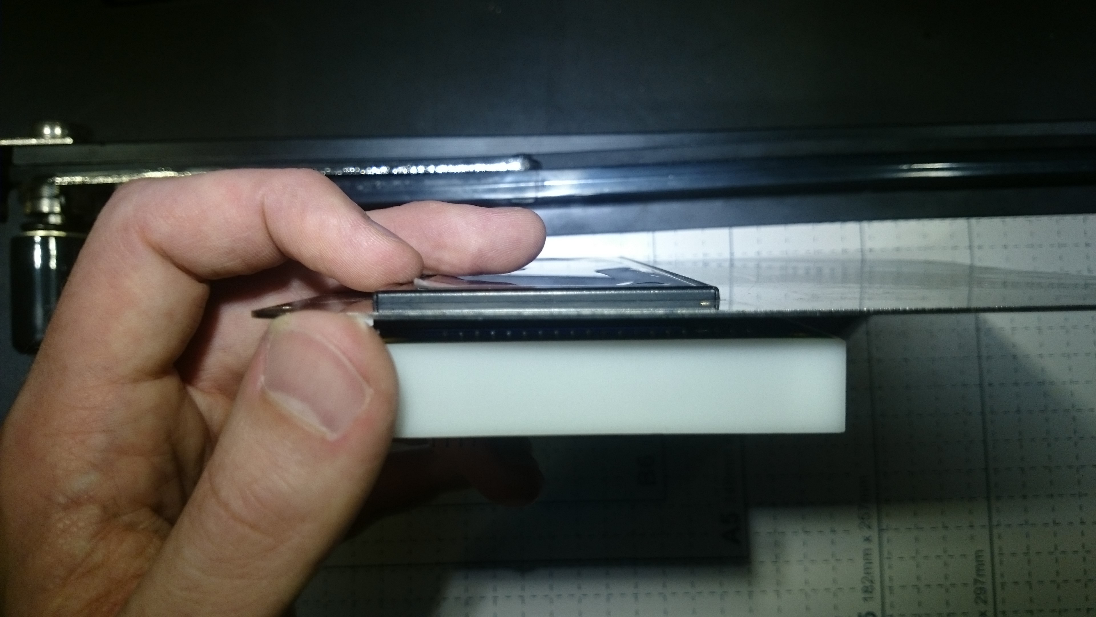
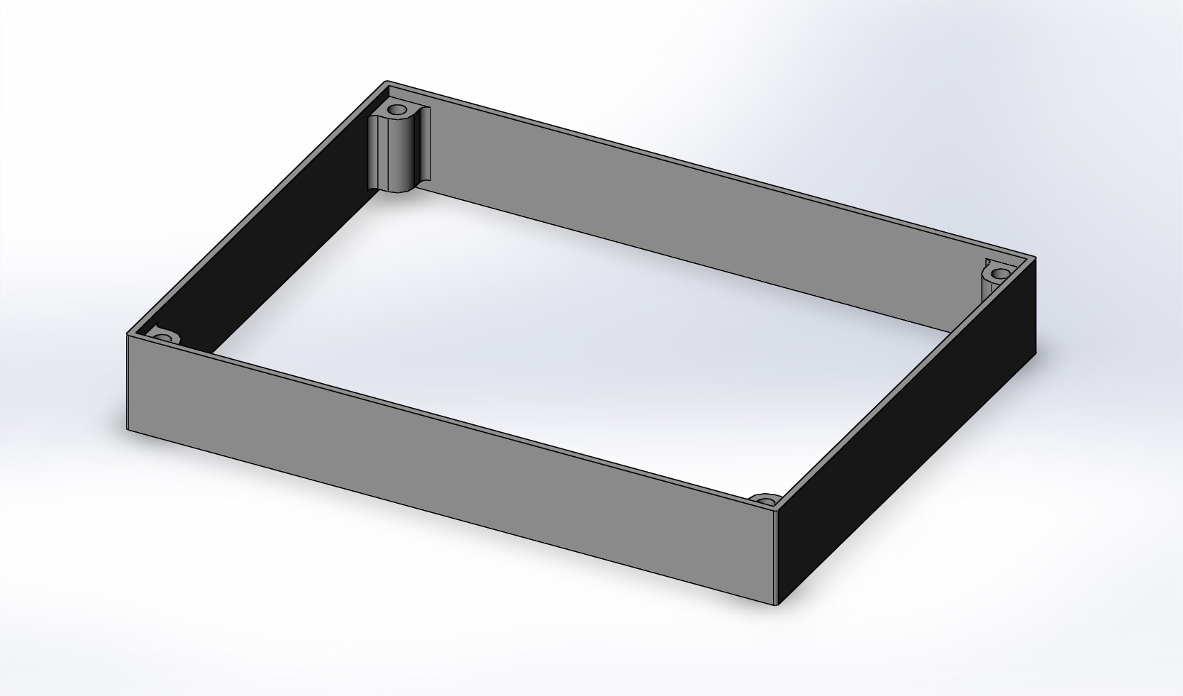
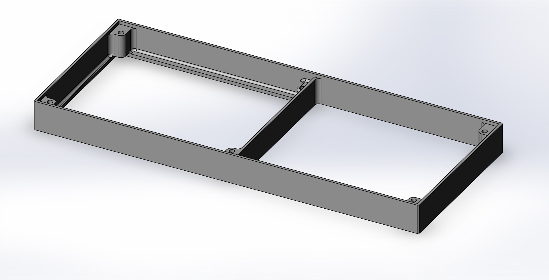
Other LCD modules might not fit into the brackets, but are also possible with a ribbon cable.

 Leigh Oliver
 Mile
Mile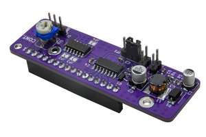
 Dilshan Jayakody