 Mile
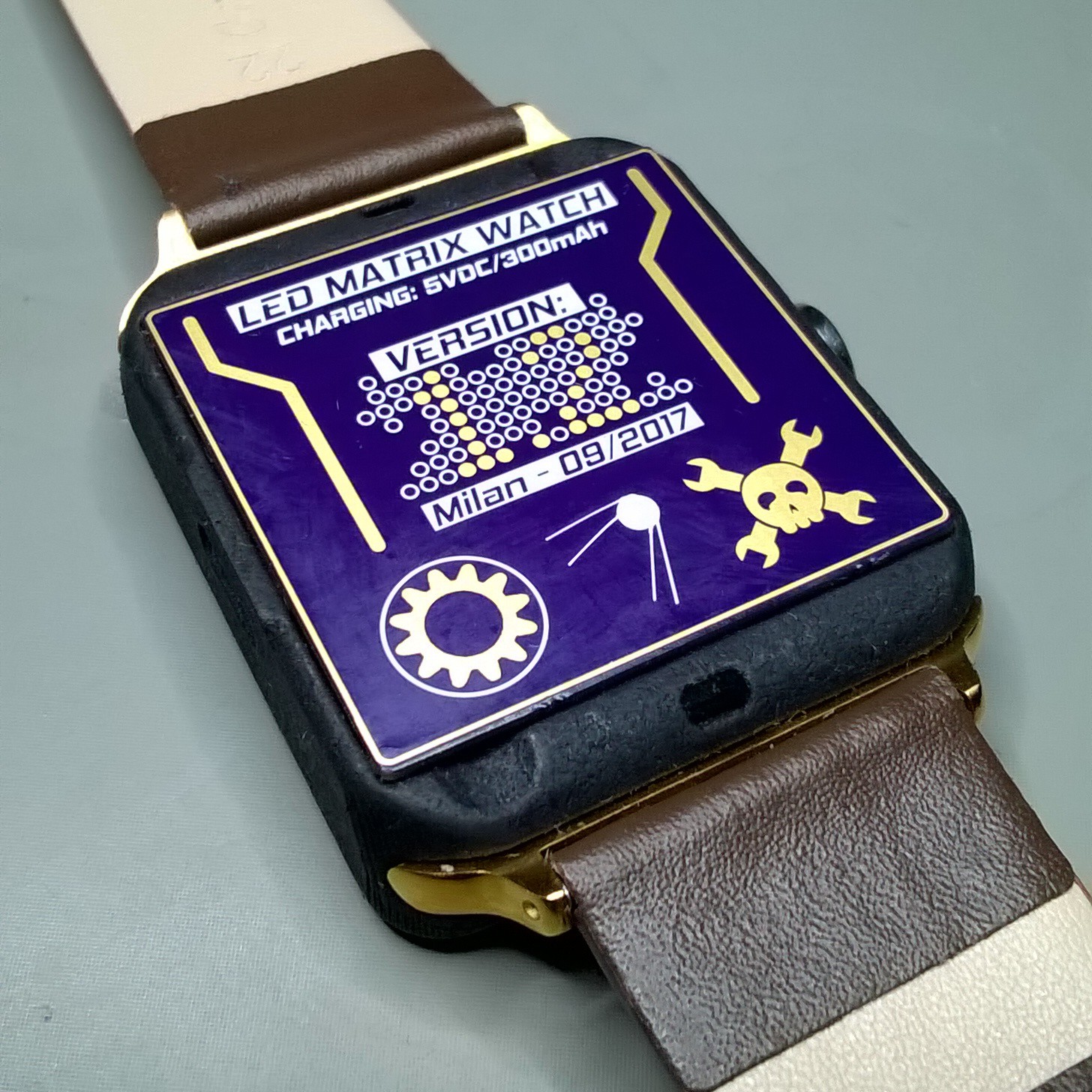
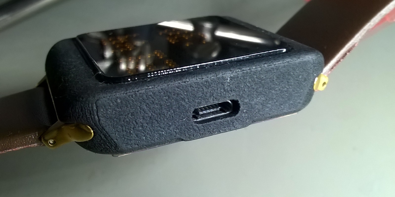
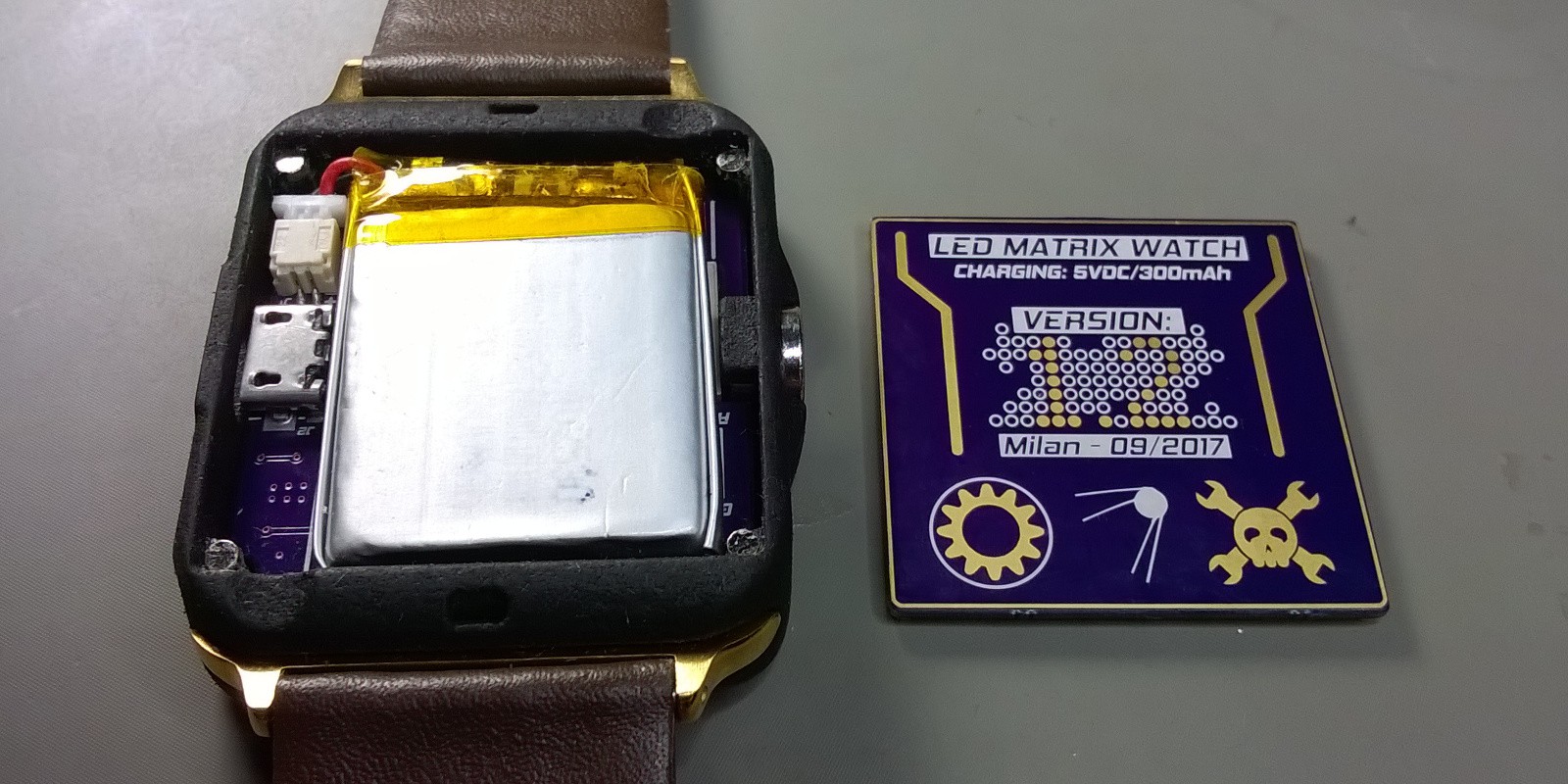
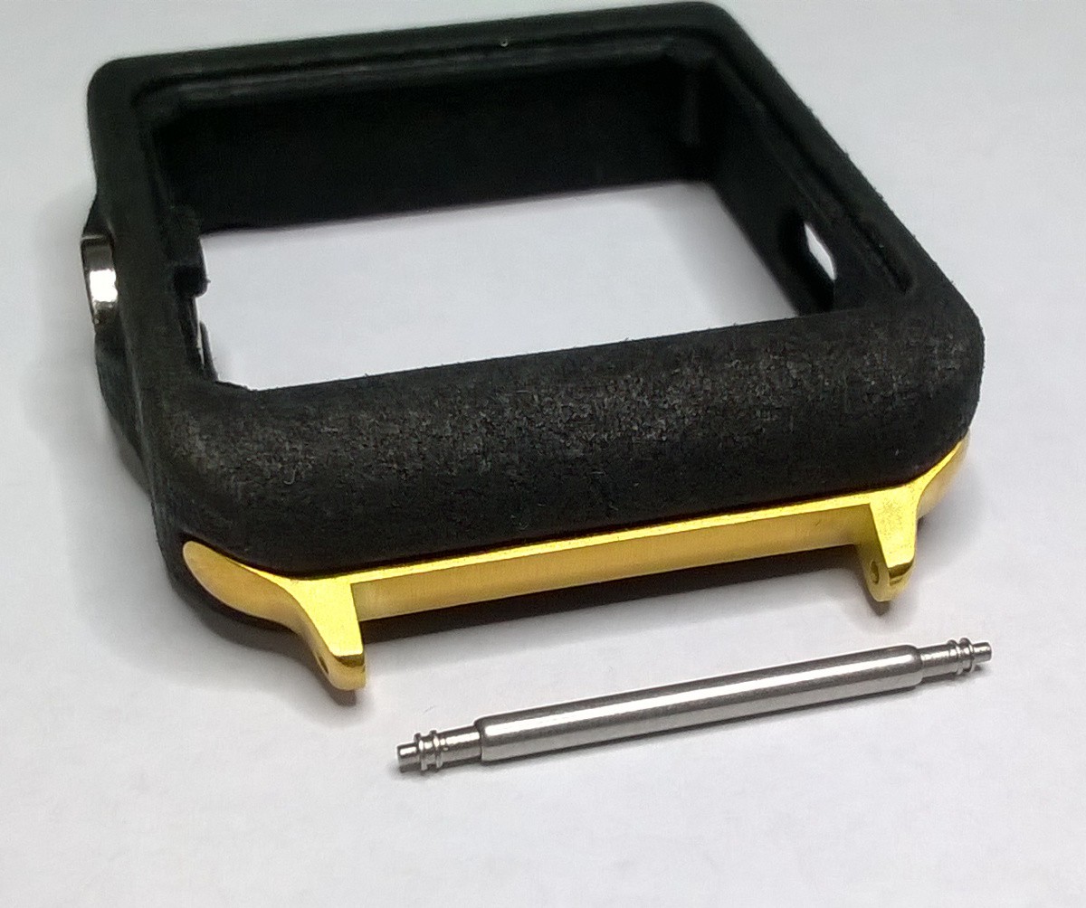
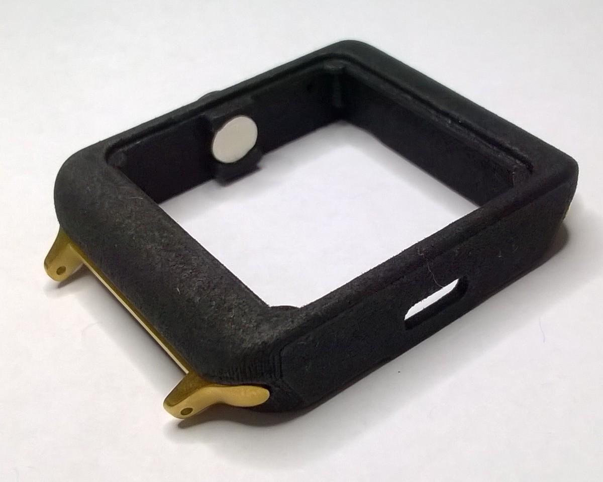
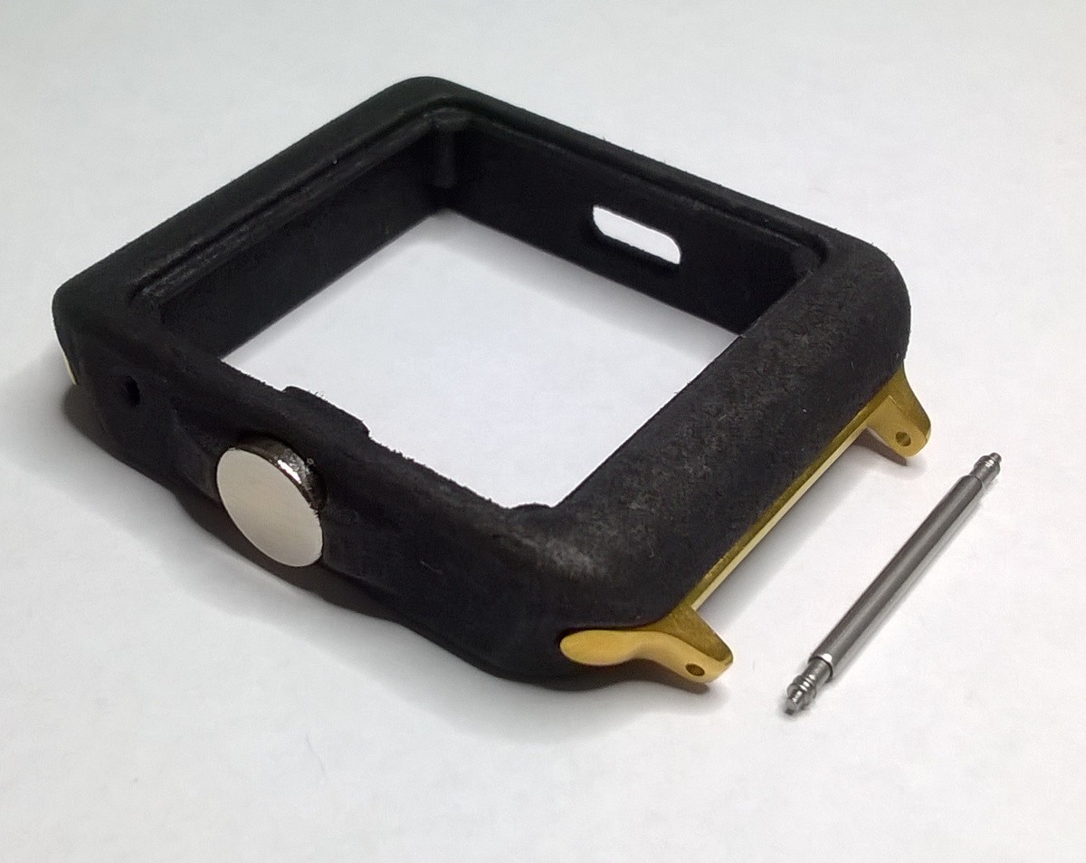
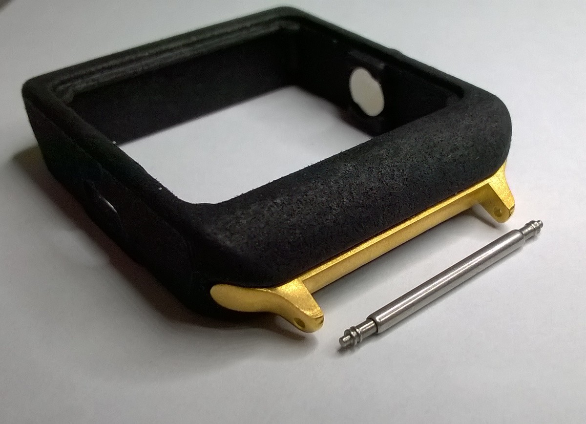
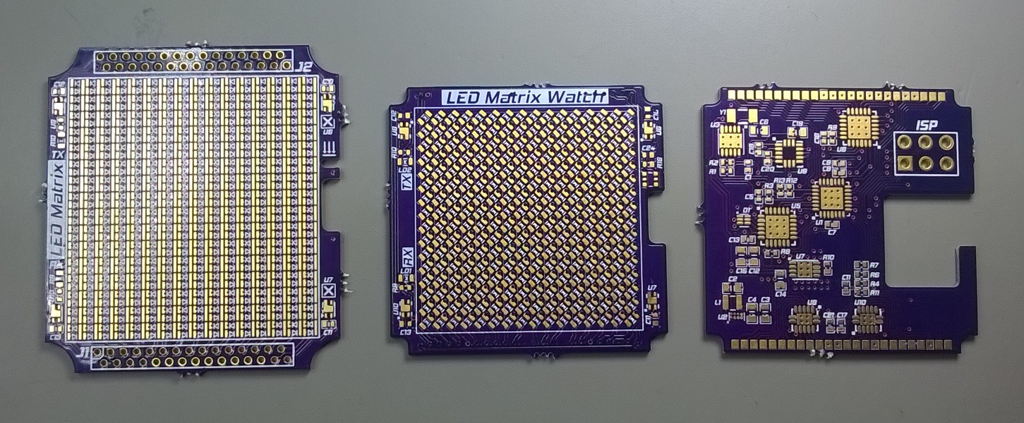
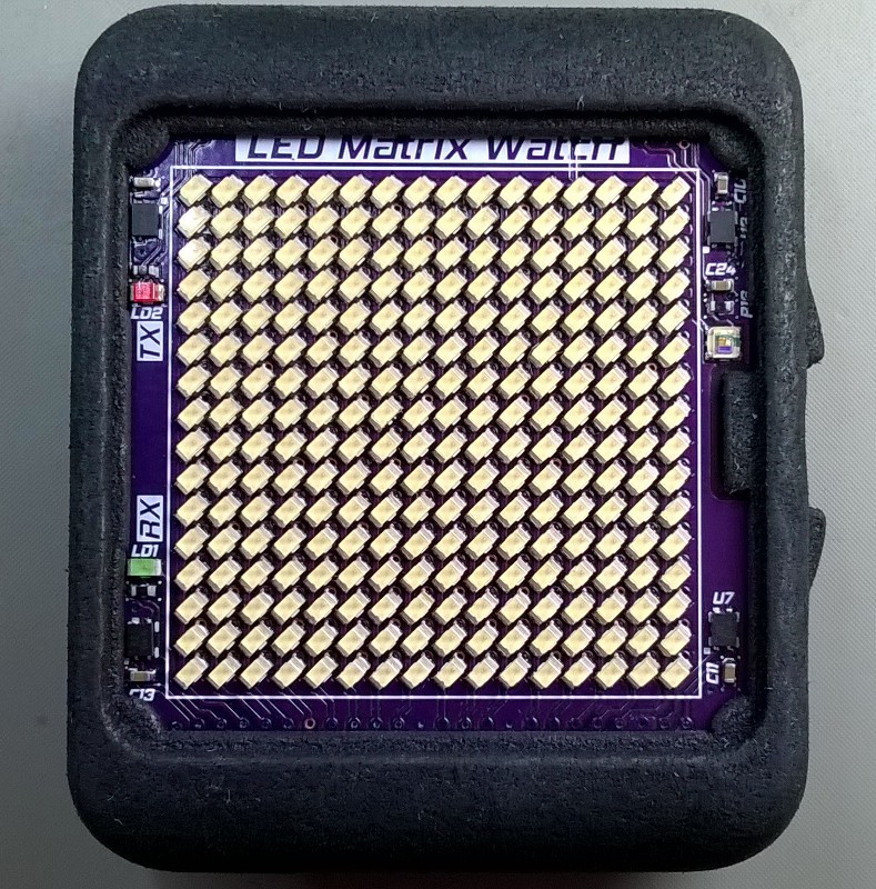
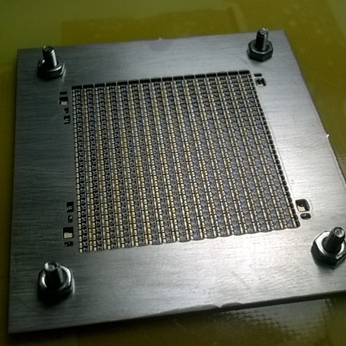
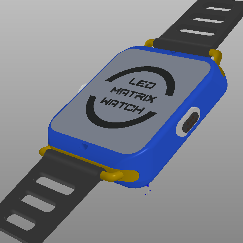
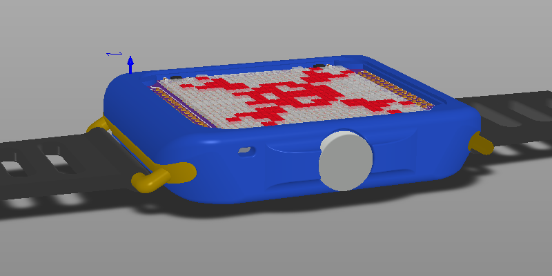
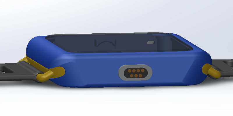
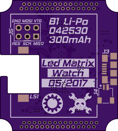
MileWatch assembly is made out of 3D printed body, smoked acrylic used as screen cover, back cover pcb, strap adapters for 22 mm strap, electronics and magnets.
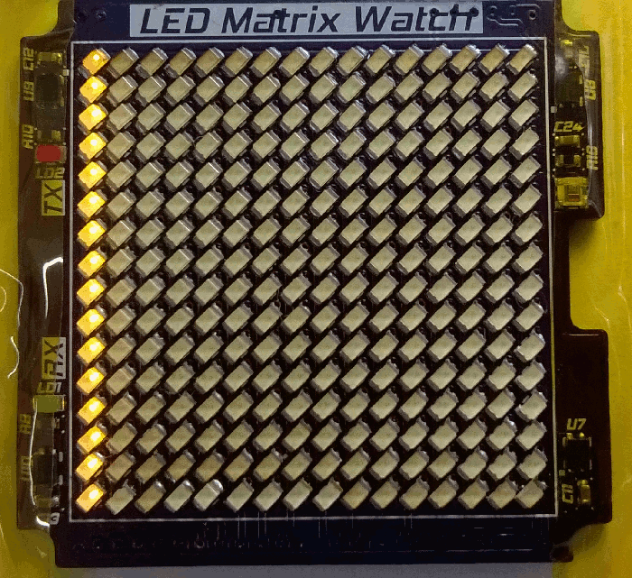
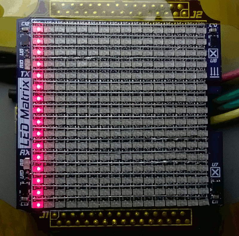
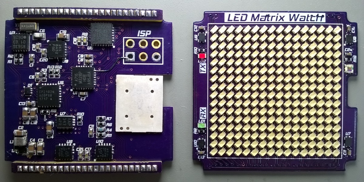
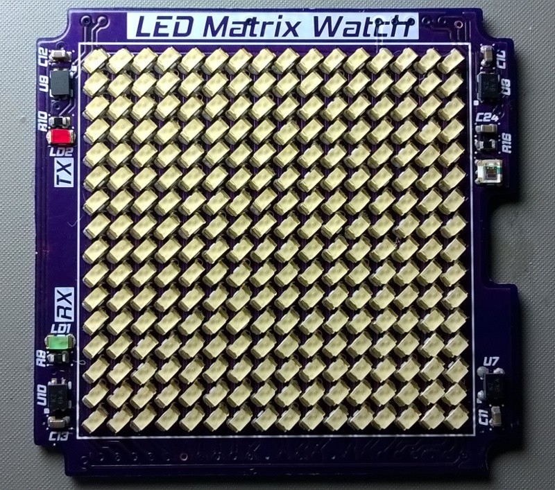
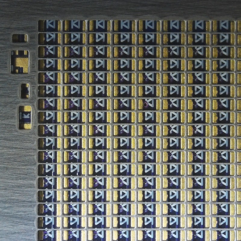
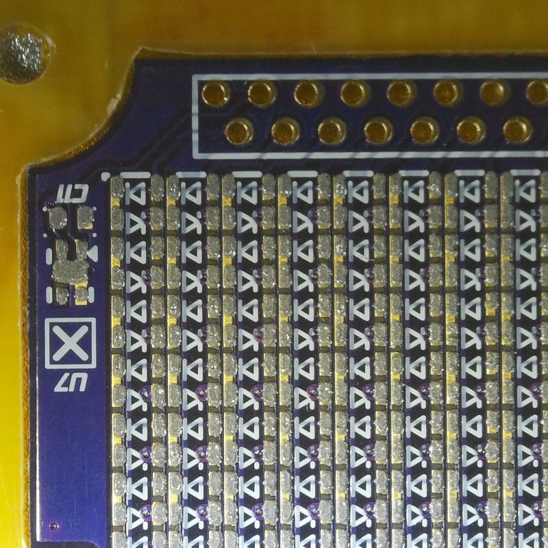
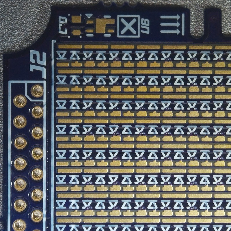
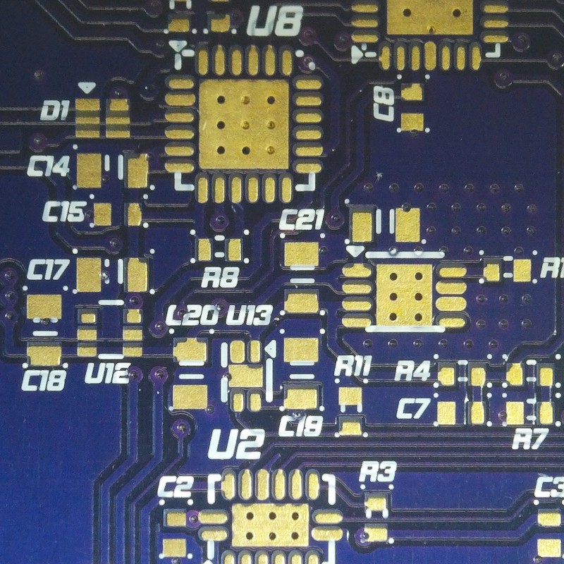
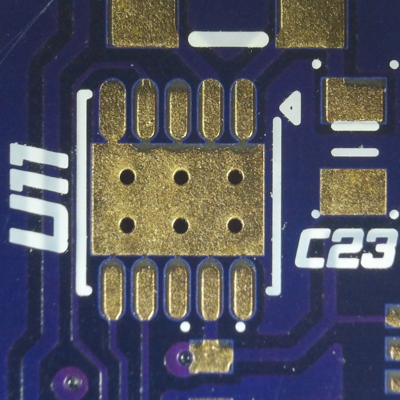
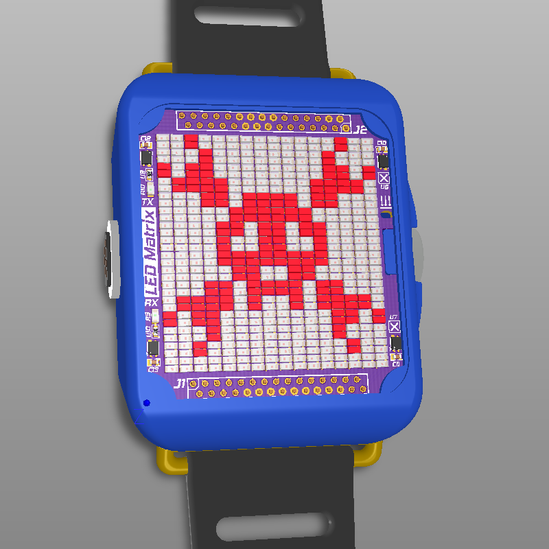
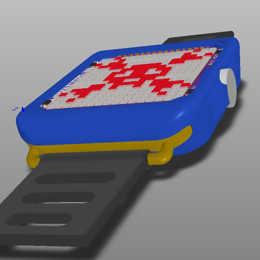
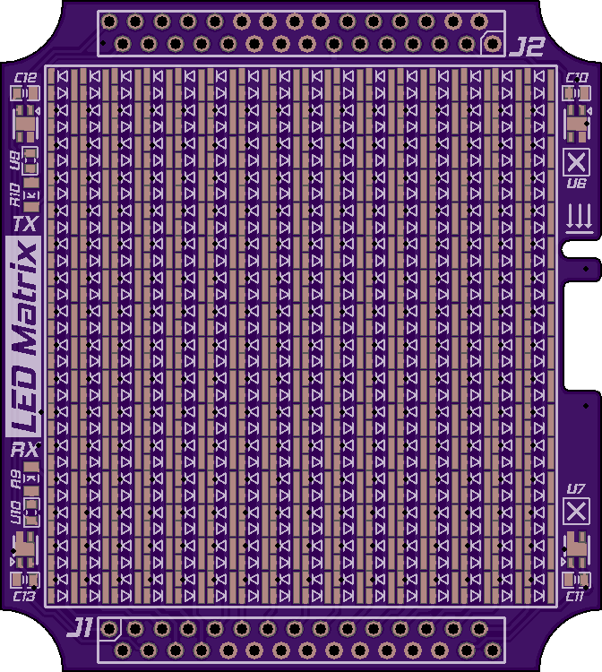
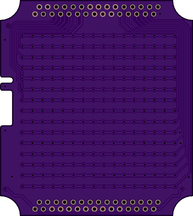
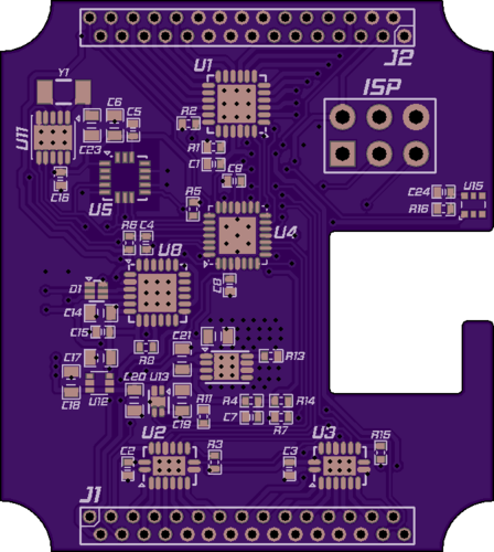
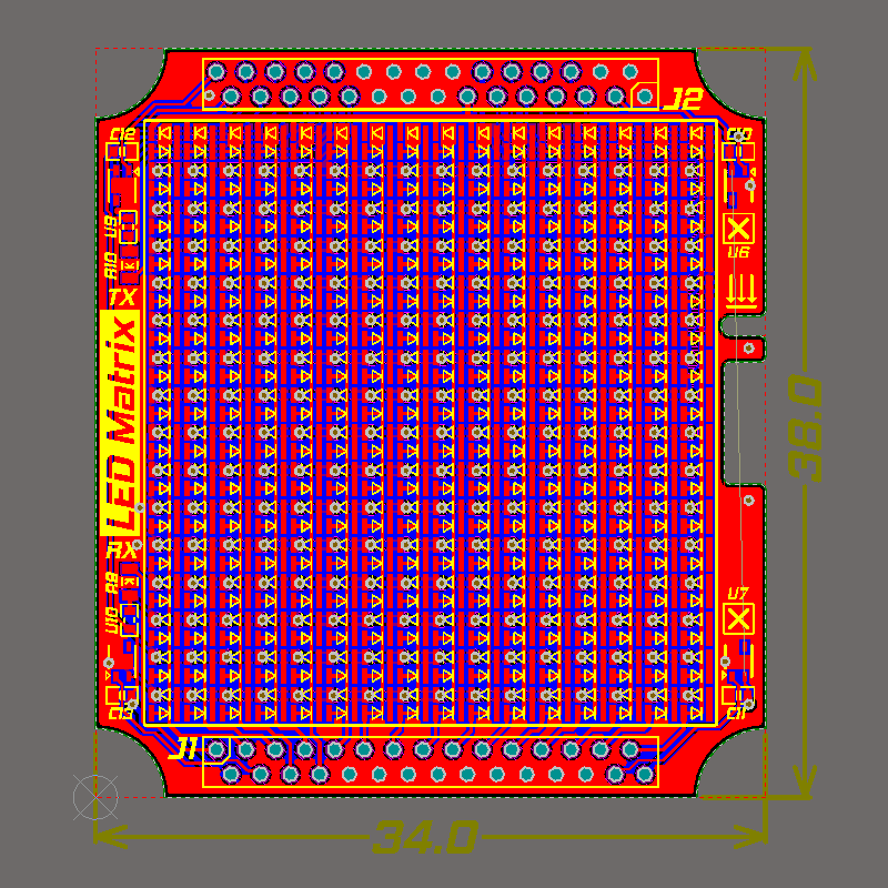
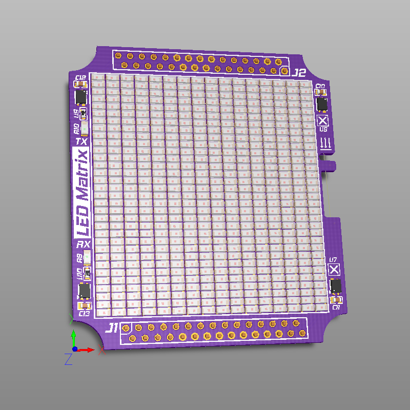
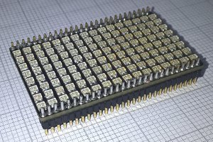
Electronics are made out of two PCBs arranged in "sandwich" structure. Top board holds 16x16 matrix while bottom board holds electronics for driving the matrix.
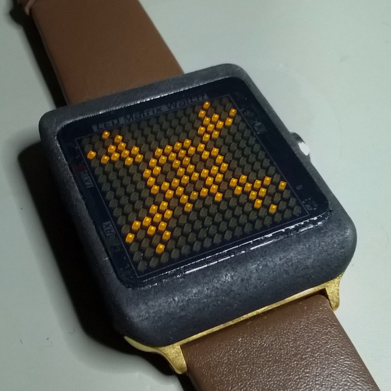
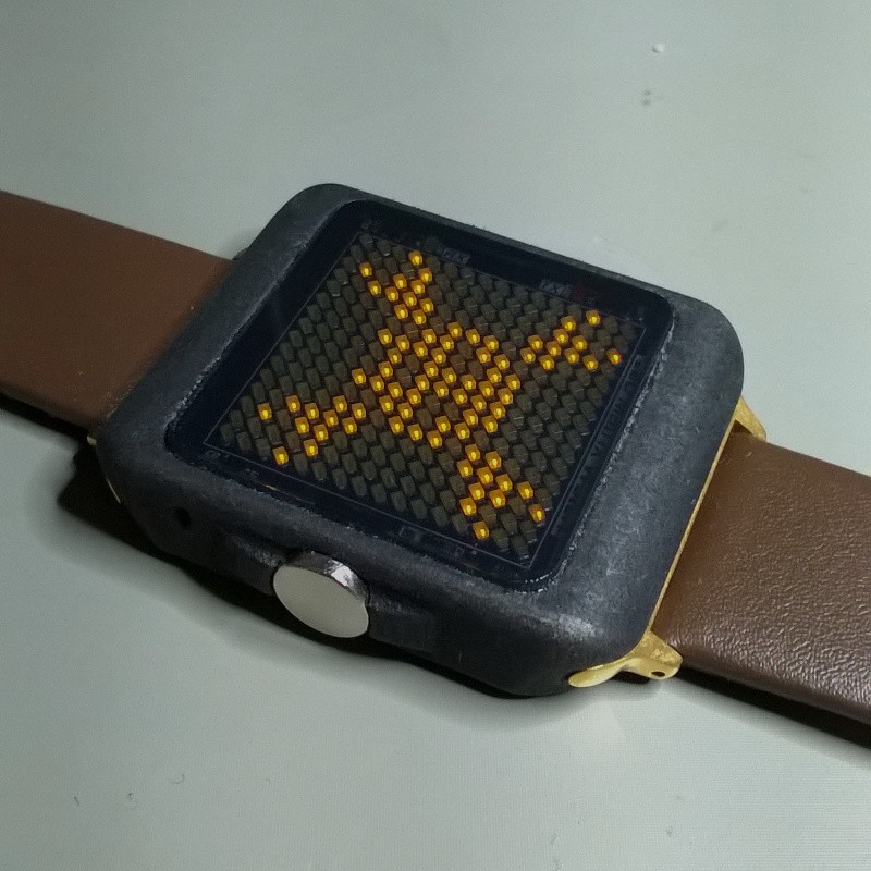
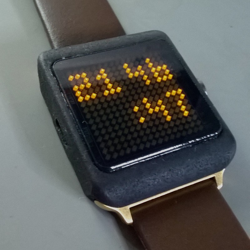
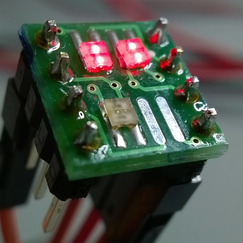
Matrix is made up out of tightly spaced 0603 LEDs. Since matrix is diagonally 1.38 inches long that means that the screen has pixel density of 16.3 ppi.
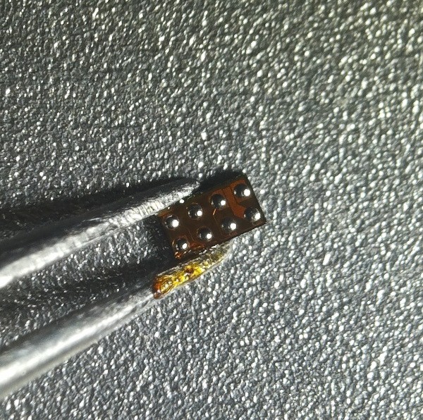
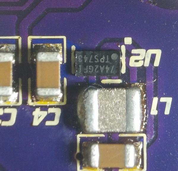
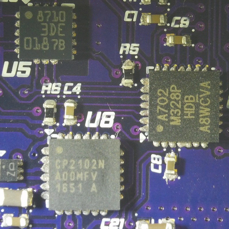
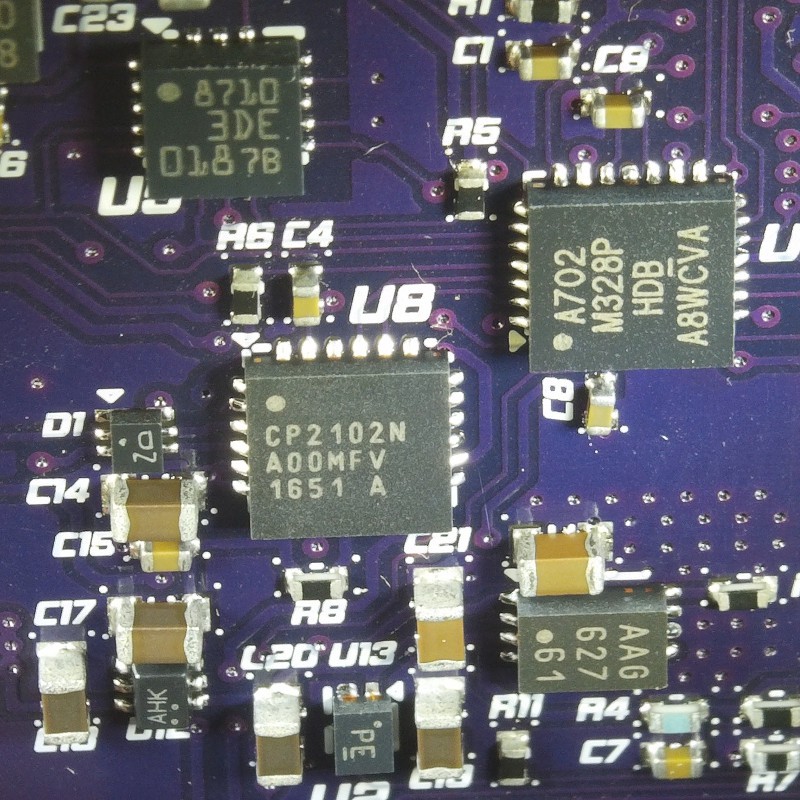
Texas Instruments TLC59282 16ch constant current LED driver in combination with two 74HC164 shift registers is used to drive LED matrix. TLC59282 can sink up to 45mA of current and has an option to set current through each channel down to 2mA.
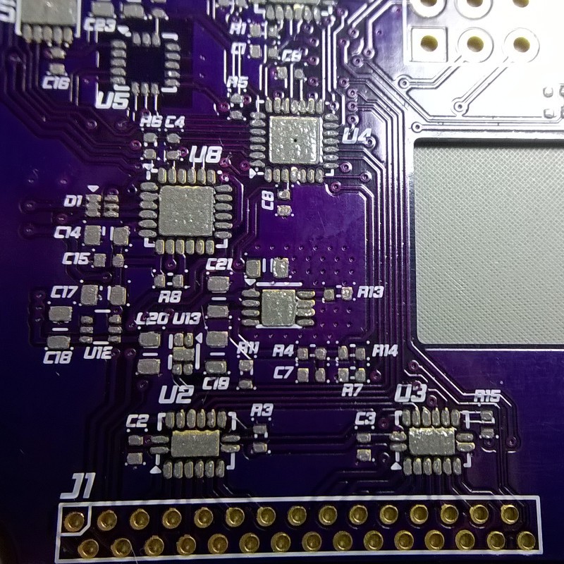
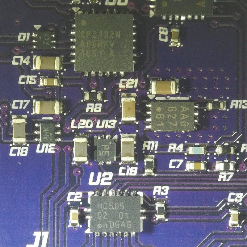
Silicon Labs CP2102N does USB to UART translation so that se ATmega328P can be programmed via microUSB connector. ESDR0502N is located on USB data lines to provide ESD protection.
As replacement for mechanical switches AH3360 Hall effect switch IC is used. Not using mechanical switches makes enclosure sturdier(no moving parts) and eliminates the need for debouncing and makes enclosure easier to 3D print. Downside is that each Hall switch uses 7uA of current on average.
For keeping track of time and date PCF8563 RTC is used. PCF8563 has integrated capacitor on its OSCO so putting external capacitor only on OSCI pin is needed. Changing the external capacitor on OSCI pin makes it possible to compensate oscillator frequency offset due to parasitic capacitance of PCB traces.
Ambient light sensor APDS-9005 is used to adjust brightness of the dispaly depending on the availability of ambient light which in turn helps with decreasing power consumption.
Battery is charged via single-cell charge management montroller MCP73831. Lithium-Polymer cell is charged to 4.2 with set current of 300mA. Depending on the version MCP73831 supports variuos preconditioning and end of charge modes of operation. Maximum charging current can be set to 500mA. Load sharing circuit is not implemented since the circuit while inactive enters low power mode.


 Erik Bosman
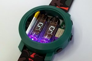
 Alex
Alex
great job