 edensrock
Finally, an affordable signal generator for everyone!
ERASynth is a high quality portable signal generator at a price point affordable by everyone including makers, students, universities, research labs, and start-ups.
- Makers/Hackers: RF signal generators are expensive pieces of test equipment typically only accessible by pro engineers. ERASynth removes the cost barriers and makes quality RF signal synthesis accessible to everyone, especially budget-conscious makers.
- Students: ERASynth is for everyone who wants to learn how signal generators work. Since it is open source with open schematics, students or anyone who is curious about the inner details of signal synthesis can learn from ERASynth.
- Professionals: Professional engineers will find ERASynth is a very good alternative to many of their existing signal generators.
- Professors/Researchers/Start-ups: With all the cuts in research funds, who can afford to spend tens of thousands on signal generators?
- Anyone else :
ERASynth is for anyone interested in RF testing. Below is a short list
of application areas where users can take advantage of ERASynth:
- General purpose RF testing. For example, to measure the gain of an amplifier, ERASynth can be used as the source.
- Test signal source for SDR. People who are using any of the many SDR platforms can use ERASynth as the test signal source for testing and calibration of their SDR devices.
- An agile LO source for up and down-converters.
- Clock source for ADCs and DACs. When equipped with an optional OCXO, ERASynth’s jitter performance exceeds the requirements of state-of-the-art giga-sample data-converters.
Features & Specifications
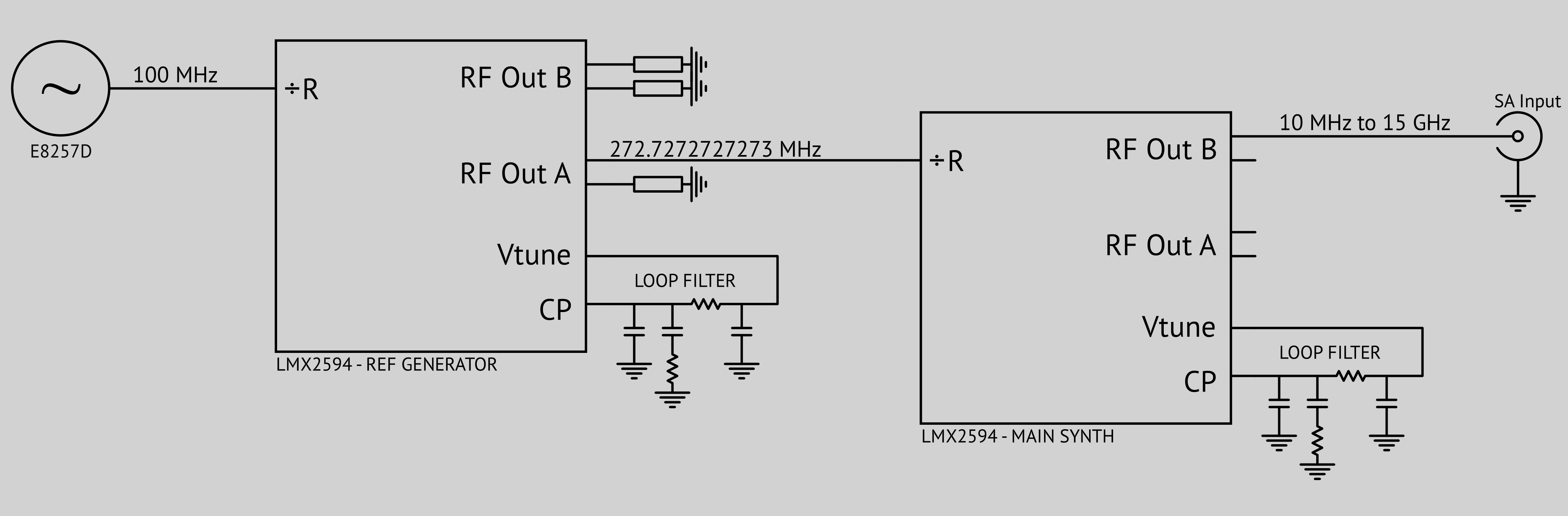
- Architecture: Multiloop Integer-N PLL driven by a tunable reference. No fractional-N or integer boundary spurs
- Frequency Range:
- ERASynth: 10 MHz to 6 GHz
- ERASynth+: 250 kHz to 15 GHz
- Amplitude Range: -60 to +15 dBm
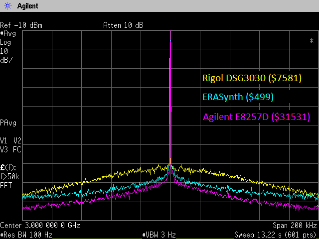
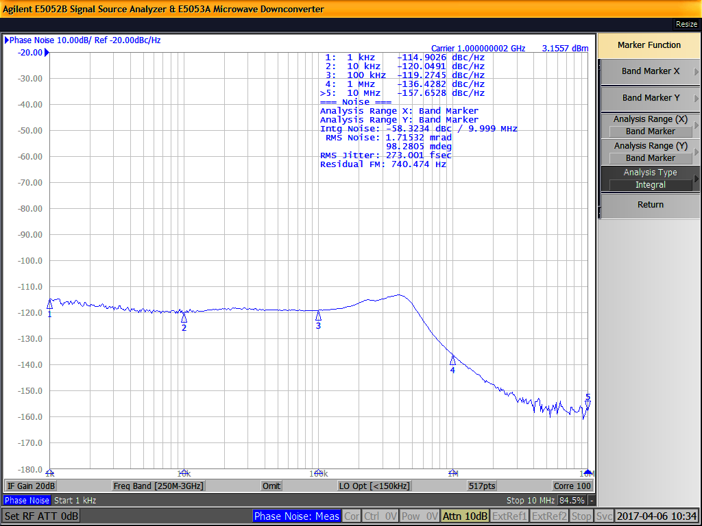
- Phase Noise: typical phase noise @ 1 GHz output and 10 kHz offset
- ERASynth: -120 dBc/Hz
- ERASynth+: -125 dBc/Hz
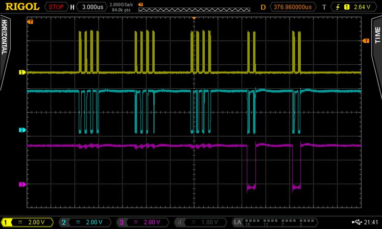
- Frequency Switching Time: 100 µs
- Reference: Ultra-low noise 100 MHz VCXO locked to a
- ±0.5 ppm TCXO for ERASynth
- ±25 ppb OCXO for ERASynth+
- MCU: Arduino Due board with BGA package Atmel Microcontroller (ATSAM3X8EA-CU)
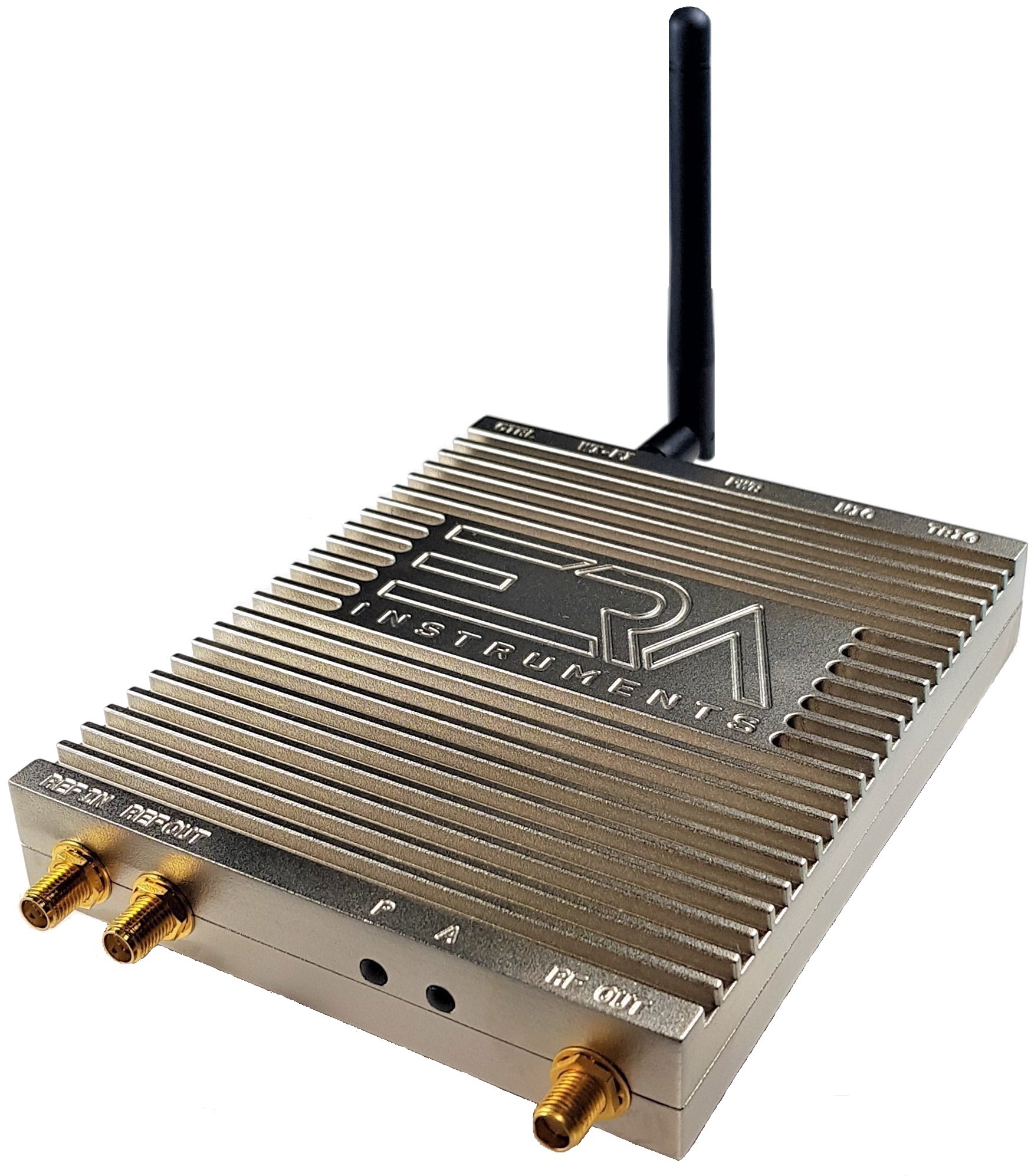
- Interfaces:
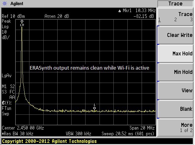
- Wi-Fi interface for web-based GUI access
- Serial-USB (mini USB) for serial access
- Micro USB for power input
- Trigger Input (SMA) for triggered sweep
- REF In (SMA) for external reference input
- REF Out (SMA) for 10 MHz reference output
- RF Out
- Dimensions: 10 cm x 14.5 cm x 2 cm
- Weight: < 350 g (12.5 oz)
- Power Input: 5 to 12 V
- Power Consumption:
- < 6 W for ERASynth
- < 7 W for ERASynth+
- Enclosure: Precision-milled, nickel-plated aluminum case
- Open Source: Schematics, embedded Arduino code, Web GUI source code, and RS-232 command set
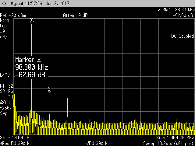
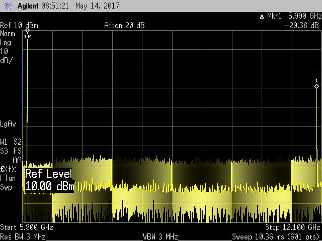
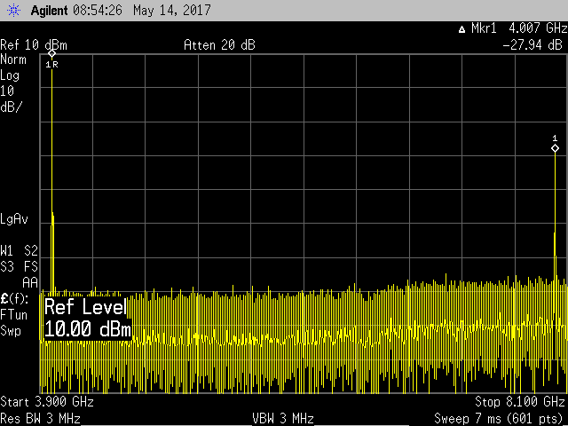
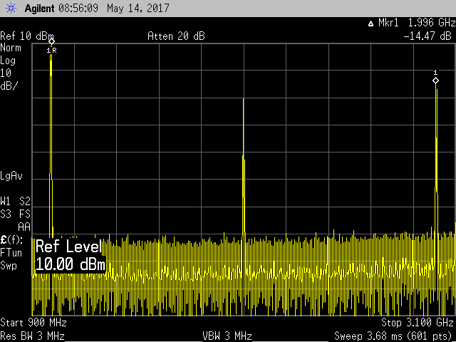
ERASynth Eliminates Integer Boundary Spurs and Improves Phase Noise
While fractional-N PLLs are great for generating frequencies with
fine frequency resolution, they suffer from a phenomenon called “integer
boundary spurs” (IB spurs). 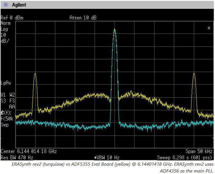
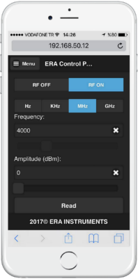
ERASynth Control Panel
The control GUI is purely web-based (thanks to ESP8266), hence we will not provide any app for ERASynth. There are several reasons for that. Firstly, web GUI is platform independent. Secondly, it is more reasonable to support one web app instead of so many apps on different platforms. Lastly, the web GUI is very responsive and mimics apps very closely. It is almost like an app, looks and feels like an app.


 Capt. Flatus O'Flaherty ☠
 biemster
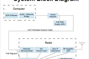
 W5VO
W5VO
Hi, did you have any stability problems with the SKY65017 amplifier? It seems to be conditionally stable between 3.5 and 6.3 GHz.