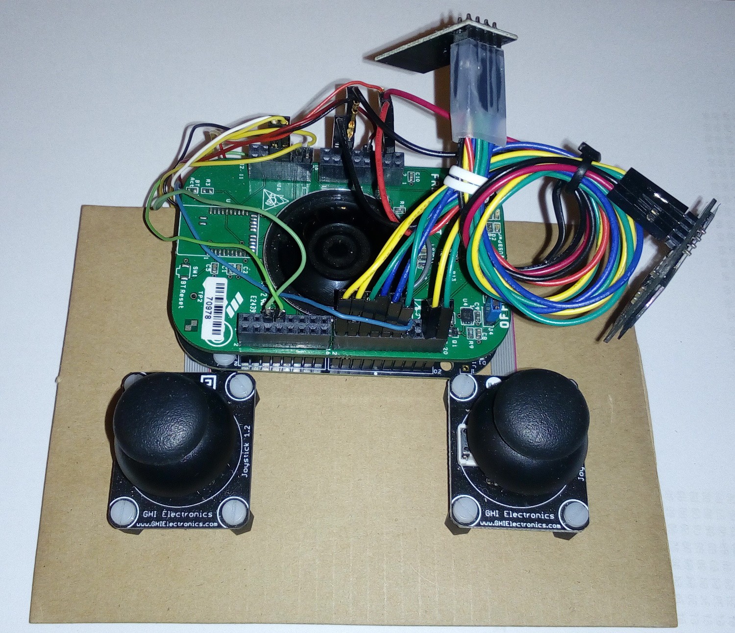
• Disassembling the Devo 7

    Roman Gassmann10/08/2017 at 15:37 0 comments

    After I received the Devo 7, I had to figure out how I can reuse its parts. Beginning with the most important (and also easiest) ones, the joysticks. Basically just some potentiometers which can be connected to the ADC of the uC (don't forget the RC-net for a basic filtering). Next part that had to be investigated was the display. After some logic analysing and research, I found out that the display features a HT1622 controller. With that known, I quickly was able to initialize the display. So the only thing left to do was to find the correct assignment of the segments. Even though, this was an easy task it took me a while (I also had to define the "Font" to write with the given segments). But hey, who said it's a work for 5 minutes, right? So after I was able to reuse the display... how about those buttons? Again some hacking revealed their connection to the uC (as expected in matrix form). Well that should be an easy part to reuse: just copying the matrix - connection. So keep on going to the next thing, the switches. Well the original board uses a HC589 to get the states of all switches. As this HC-Component is well known, why not stick with it? So again an easy and also feasible solution. This left me with just two parts left to analyse in the Devo 7. First, the beeper which is just a beeper ;-) that needs a PWM (Hi level 3V3 or 5V both are working (of course the volume at 5V is higher than at 3V3). Since it is not recommended (due to its current consumption) to drive such a component form the uC directly, a straight forward transistor network is needed here - easy again :-). So there is just one part left, the battery, that ugly pack of 8 AA-Cells. Its for sure that we wont use that in our new design. Instead I wanted to reuse a LIPO-cell from a broken phone ( one less that's laying around ;-) ). Furthermore, I should be able to charge this cell by a 5V supply through the charge-connector at the back of the Devo 7 - so some development needs to be done here but again not a big thing.

    Now the next step will be the design of the schematics and also the layout of the new remote-control main-board. And yea... already looking forward to fly my Crazyflie with a very nice remote-control :-).

  • Proof of Concept "Reverse Source"

    Roman Gassmann05/20/2017 at 13:33 0 comments

    After a basic porting of the FreeRTOS to the KL26z a first try to reverse the Crazyflie source was very successful. So the controlling part was implemented very fast and thus I could focus on the parameter and logging system of the Crazyflie. While the logging system is explained on the wiki page of the Crazyflie the parameter system had to be interpreted from source... but it turns out that this pretty easy as it has a very nice structure. So with a working logging and parameter system I finally could focus on the hardware. Since the quick & dirty set-up with the FRDM Board is hardly a long term solution, I had to come up with a better hardware. My main focus at this point was the thrust-stick, as I wasn't happy with the Joystick used for the first set-up. Its desire to go into the centre made it hard to control the height of the Crazyflie. So I was hoping to modify the Joystick to have a hold desire... unfortunately this was not possible due to its structure. So again I was searching for an alternative Stick. I checked many joysticks and was really frustrated by the fact that a more-or-less good stick would cost a lot and further more I had to build a case for my remote control! So my search went from a single Joystick to a whole remote control that could be partially reused. It truns out that the Devo 7 can be bought for less than 20$. It features two solid joysticks which will be sufficient for this project and further several switches as well as an LCD-Display. In other words: It was just perfect for this project.

  • Project Start

    Roman Gassmann05/20/2017 at 08:22 0 comments

    A while ago I received an "Attach Demo"-Board consisting of an FRDM-KL26z, a Battery-pack (FRDM-BATT) and a 2.8" Touch-screen. At that time I already made some simple implementations of the command controller for the Crazyflie on an FRDM-KL25z Board powered by USB. So the Attach Demo with its Battery seemed a good Base for some further tests. For that, I removed the Touch-screen and added two joysticks (https://www.ghielectronics.com/catalog/product/299) as well as an OLED (SDD1306) and an NRF24-Modul that I used in other Projects.

    After a little programming I had a cheap working controller for my Crazyflie. Unfortunately this fast solution didn't let me log parameters such as the battery-state and also didn't let me get or set other parameters such as the led-ringeffect. So further investigations had to be done to know how the Crazyflie works. After studying the source-code of the Crazyflie a crazy idea jumped into my mind: Why not just "invert" the source of the Crazyflie? So lets try that...