 markcra
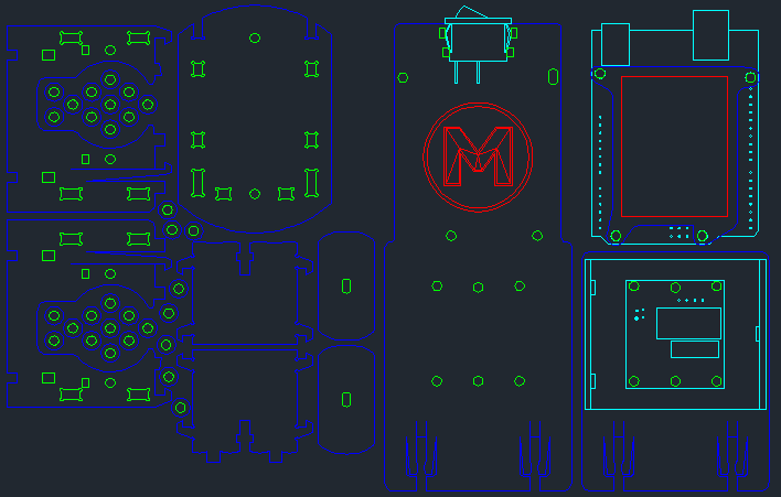
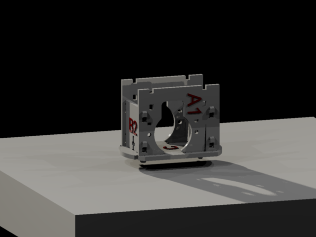
Laser cutter file (see github link opposite). Colours are: Red - etch, Green - first cut, Blue - second cut, Cyan - CAD notes. Also a file which contains the previous revisions (on github), good and bad, which might offer some insight into my design process.
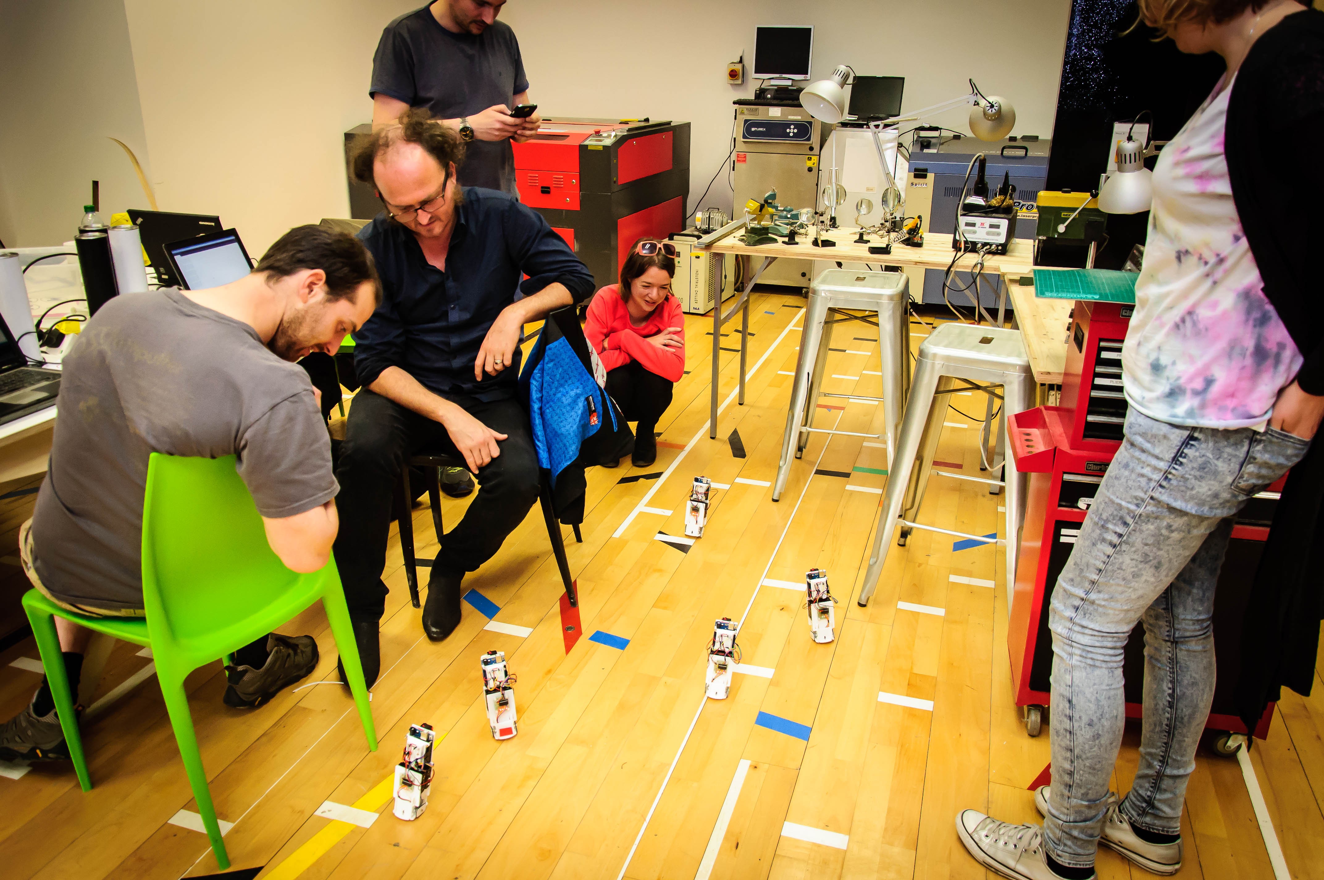
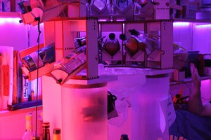
Workshop under way and the clones are preparing for their race.
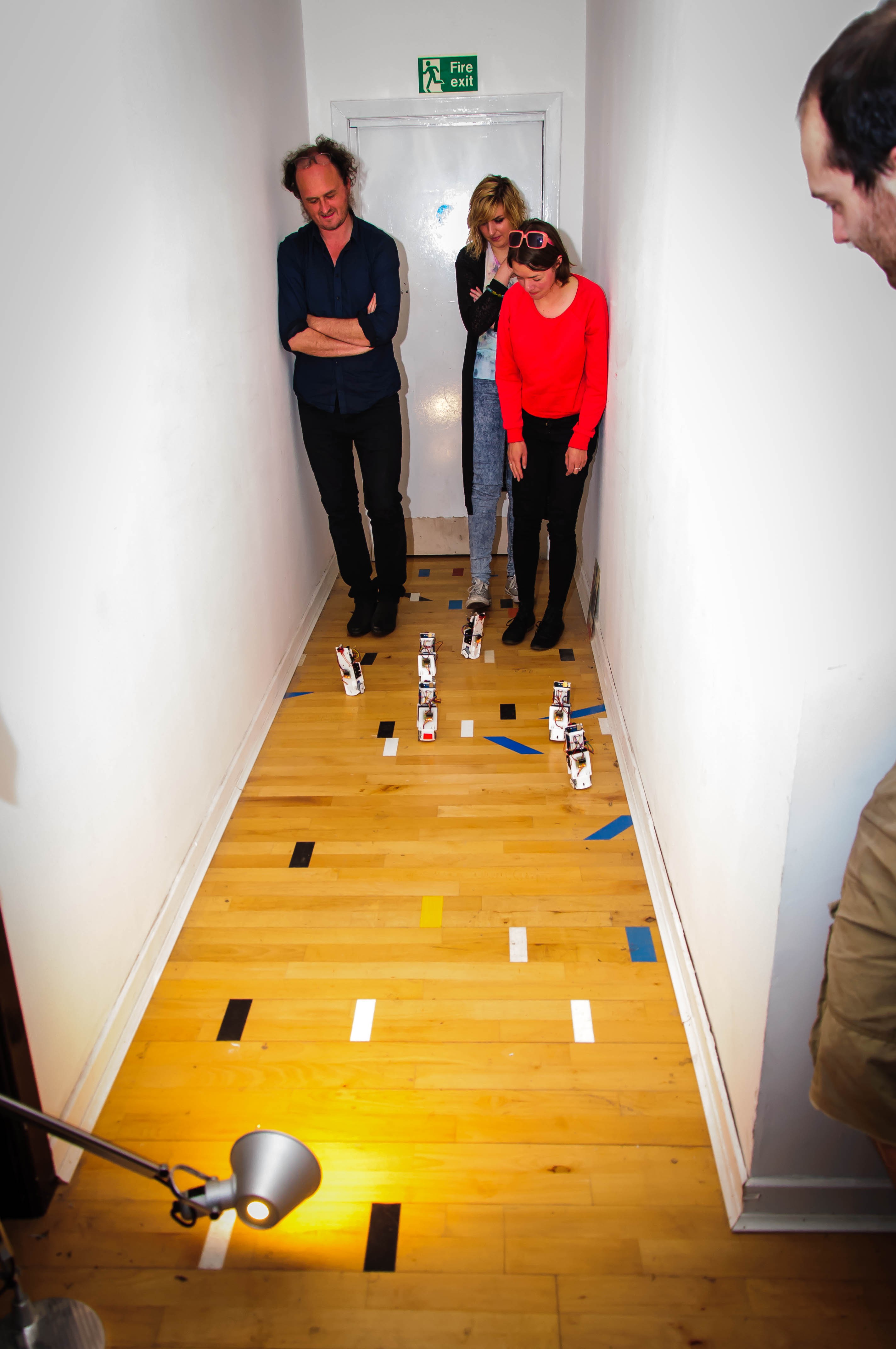
It was a gripping race, watching the robots lumber slowly along the hall there was one clear winner (we couldn't contain ourselves and declared the winner before it reached the lamp).
 Florian Festi
 Miguel Wisintainer
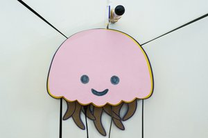
 Ahmed Azouz