 Pierre-Loup M.
This project started as a need for a photographic project of mine. I needed to make lot of overlaping exposures on a single print, with variables times. It would have been 80 single exposures, with time going from 3 to 15 minutes each. The whole process would have take more then 12 hours, staying beside the printing box.
So I picked up an Arduino mini I had lying around, a 7 segments clock display and its shift register salvaged from a TV decoder, a rotary encoder from a car audio system, and a few hours later I had already saved a lot of time!
Using it it clearly appeared that this board would have been usefull to me for many years, so I dive into designing one that could be used by photographers knowing nothing of electronics and programming, but in need of such a tool.
The main features of this board are:
- Arduino based design, running on Atmega 8.
- a large (48x18) 7 segments clock display driven by a MAX7219 chip.
- a rotary encoder to setup time.
- a large push button to start/pause/stop exposure (plus the trace on board for a second one if needed)
- a relay, for switching 12VDC led strips as well as 240VAC bulbs or tubes.
- a voltage regulator so it can be powered from led strip power unit, and
- a USB plug to power it from regular phone charger, when used with 240VAC.
- exposed pins for I2C, SPI, serial for further developpement or hacking.
The software do the following:
- set a time (!)
- start, pause, stop exposure.
- save some exposure times into persistant memory
- recall memory saved time.
The board is around 150x50x20mm, intended to be mounted inside a user-made UV box, as well as an existing one. It of course can be mouted also in a dedicated case if the user wants it!
There are screw connectors for power in and power switching on relay side, so there is no soldering needed when mouting it.
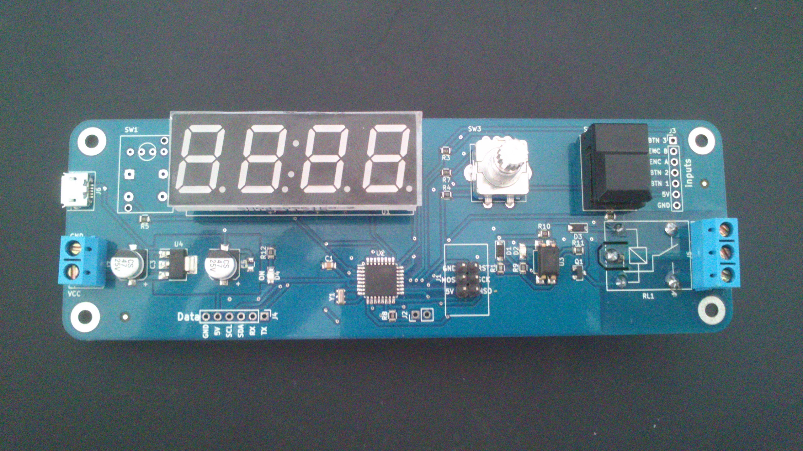 The finished timer. It just lacks the encoder button.
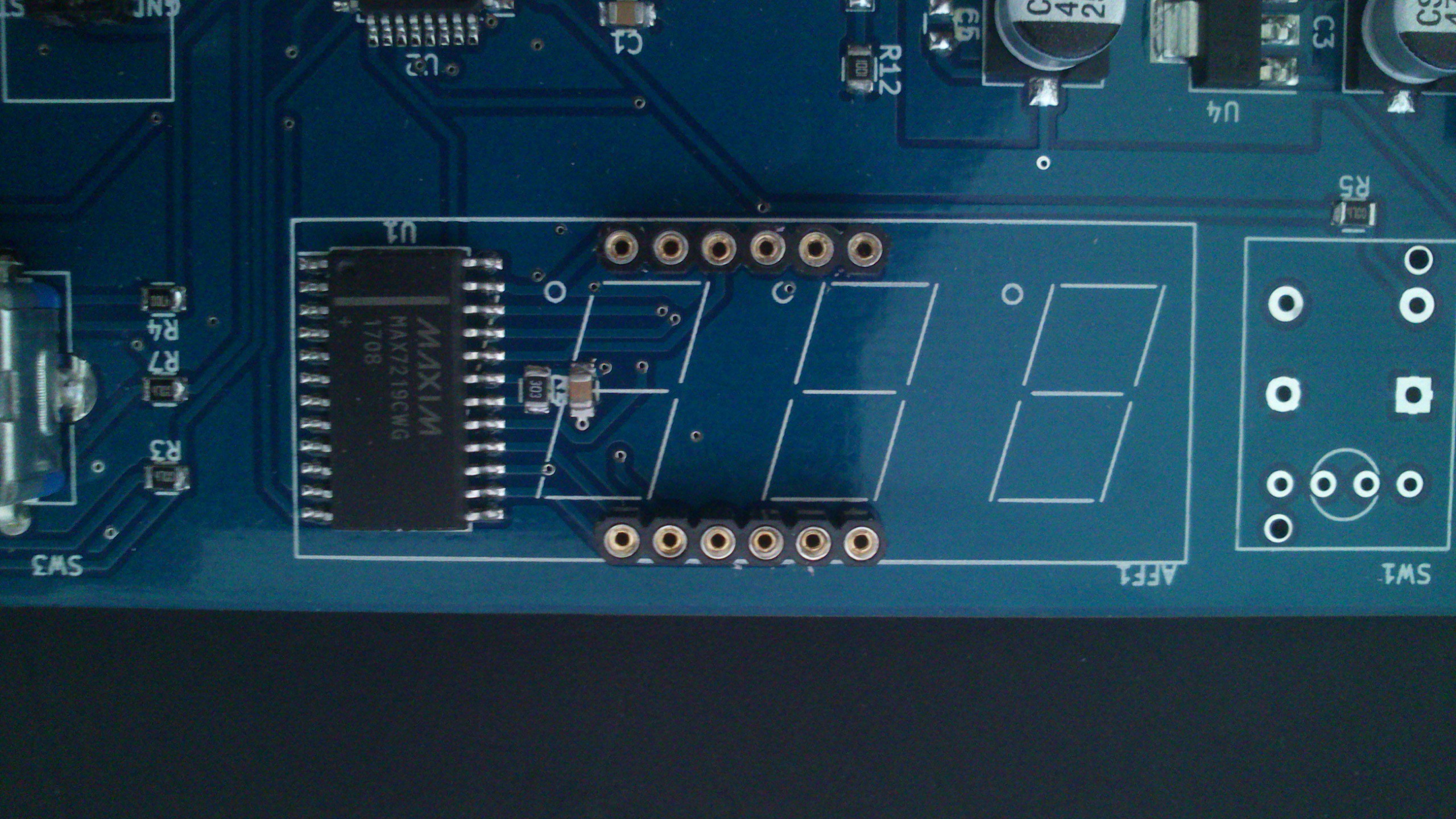 The C2 capacitor and the R2 resistor. Very close components, with the same index, I understand they swapped them. But i would have preferred they didn't! :)
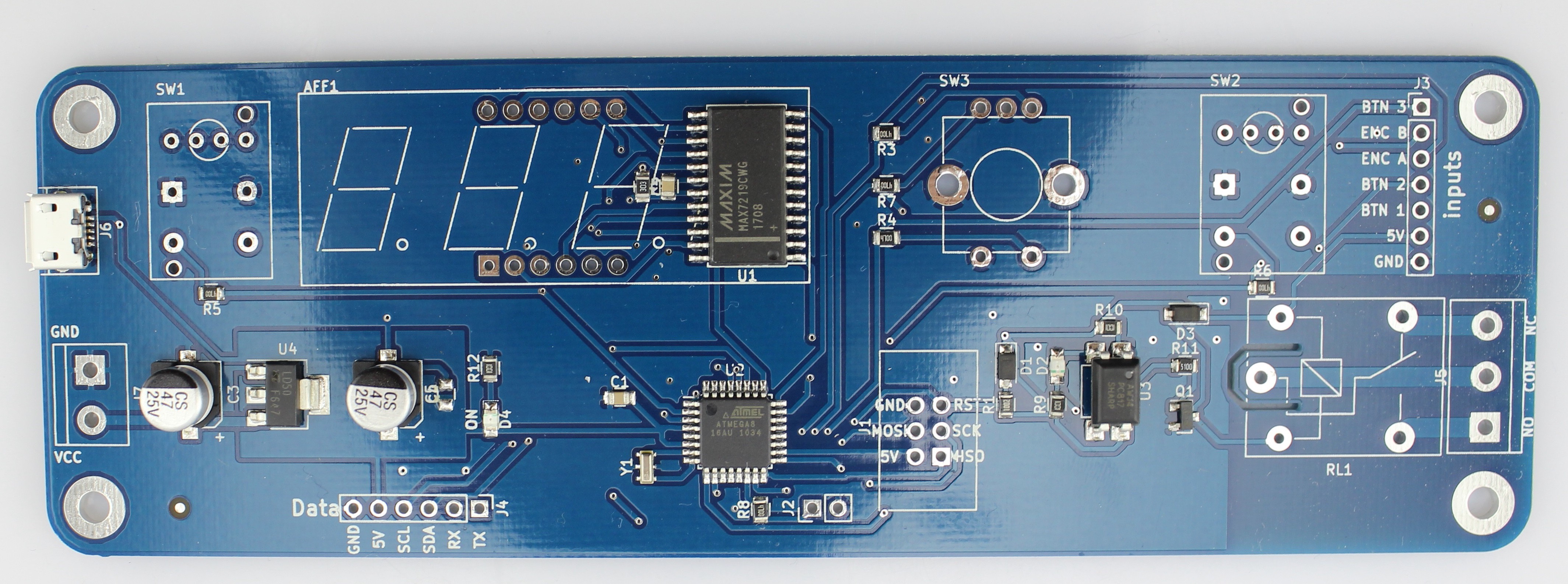

 Atheros
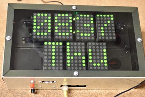
 Bharbour
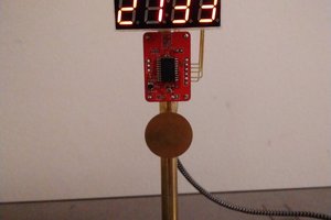

 Gorloth