 Dave
DaveThe flow of the problem is:
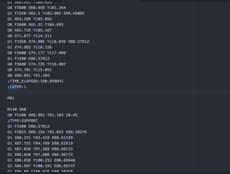
- When the printer will end, the Marlin will reads the "M81" command
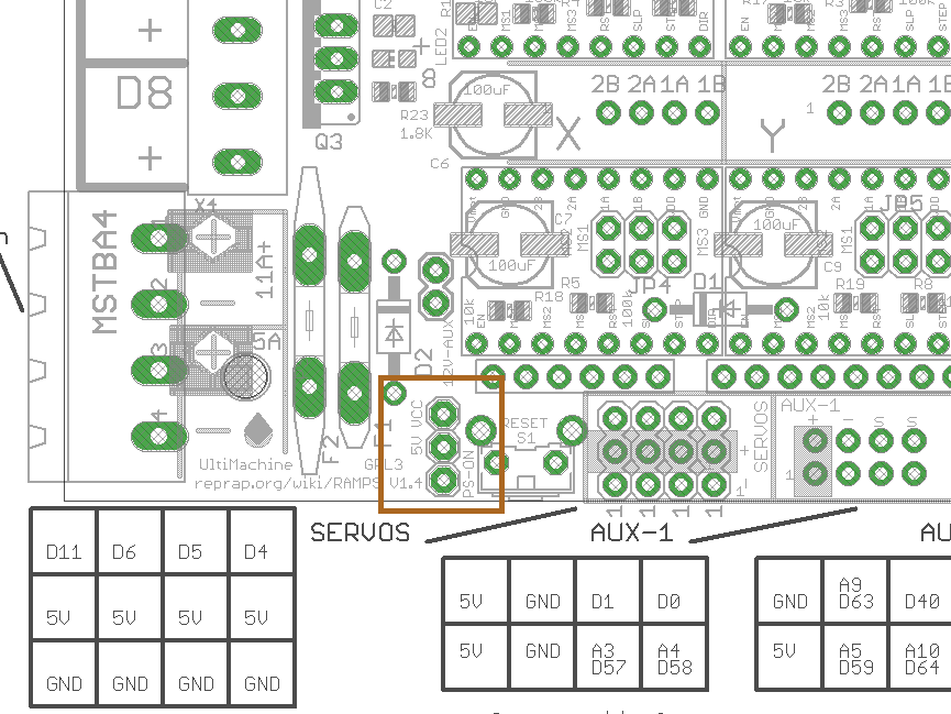
- The PS_ON pin rises
- Now the relay will open the circuit and the printer power off
- So the ramps will power off, and the PS_ON pin will fall
- The relay will close
- And in the end the printer will power on, again....
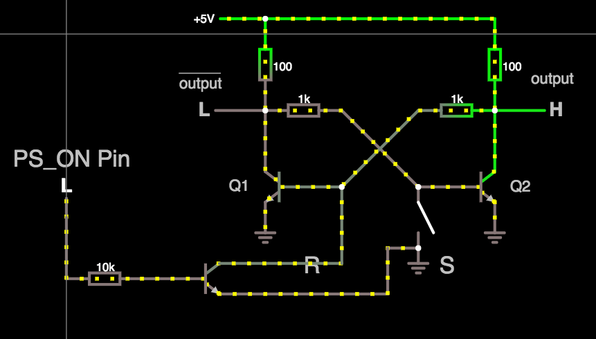
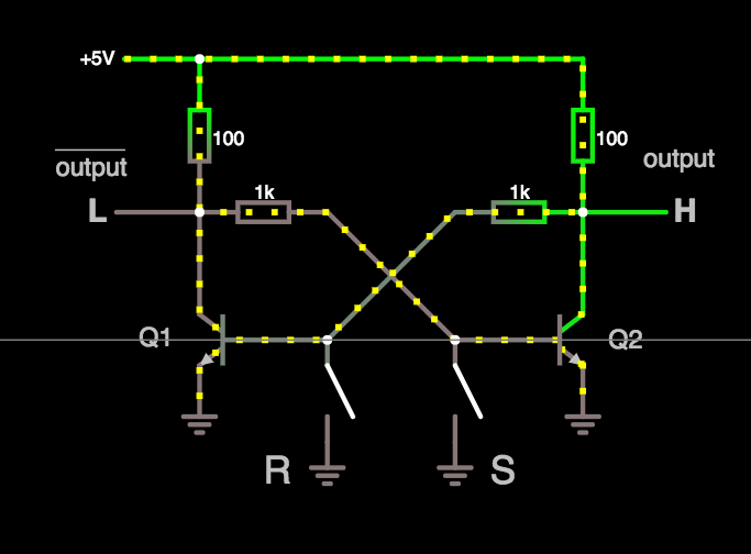
So we need something with a memory, that can remember the last state of the PS_ON pin.

 Now I created a 3D printer file with, at the end of the "final code", I entered the M81 command.


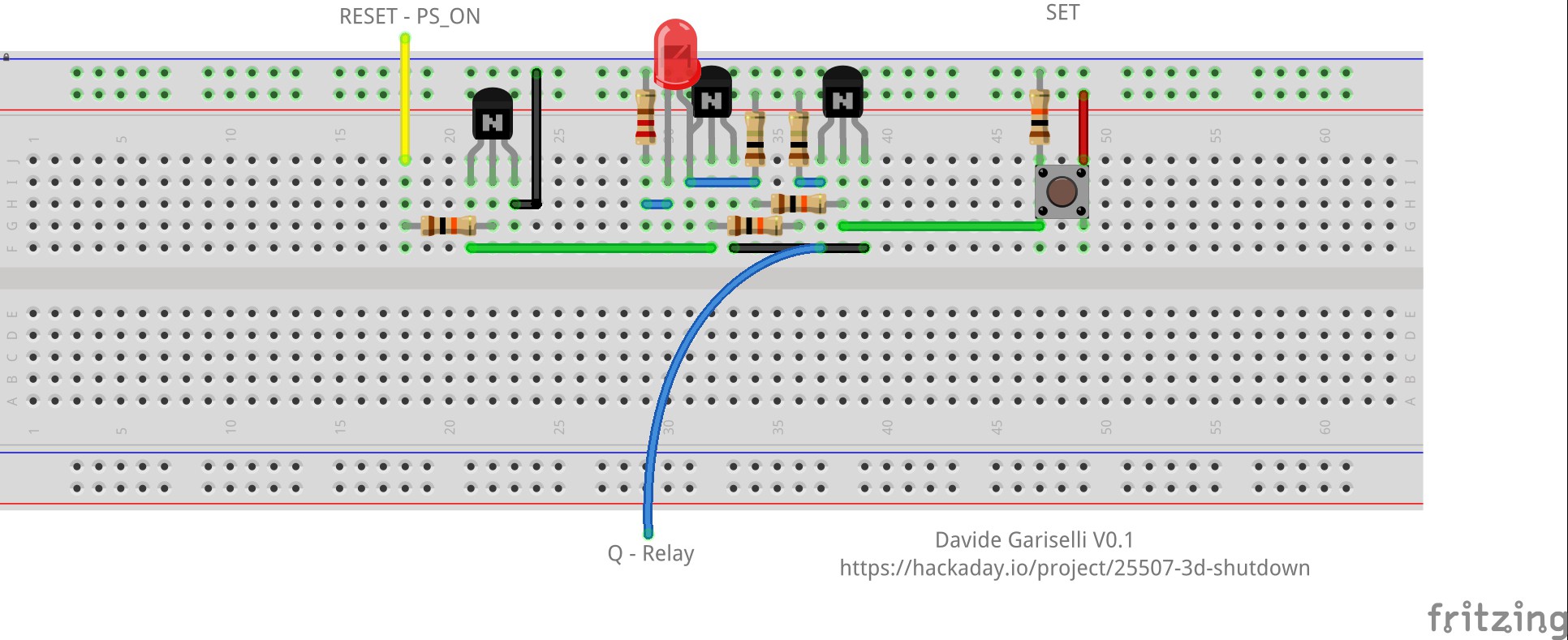
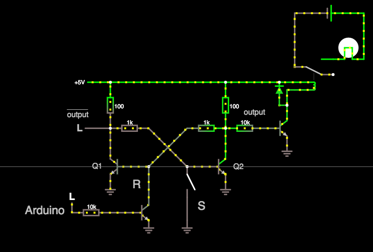

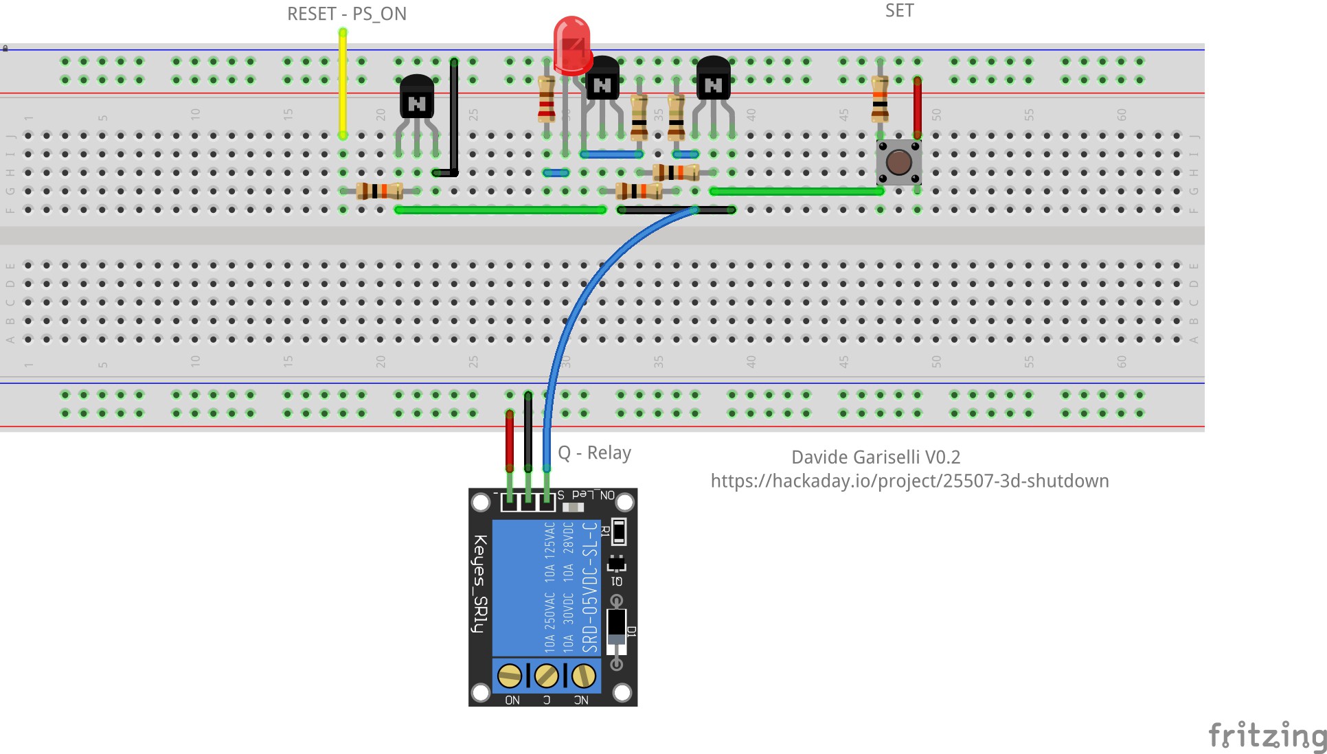
The project is outdated and there are inconsistencies:
The first thing I see when looking at Fritzz's schematic is the LED, logically it will ALWAYS be on, as both Phase and Neutral are already on.
Another easily observable thing is the number of resistors, in the material listing a total of 5 (2 types) are described, but in the schematic there are 7 of 3 types.
Another issue is when pin placement on the 2N5551 - PIN 1 is normally connected to ground and is not what appears on the wiring diagram.
Unfortunately, it is not possible to guess how the author made the wiring diagram correctly, it would be very useful if it were updated.
Grateful!