 Ben Brown
With the growing availability of cheap Lithium based batteries, having both portable off grid and fixed off grid power is becoming more attractive. Most of the BMS units commonly seen online are usually based on using TL431 based balancing circuits which while functional leave more to be desired for larger battery banks.
Design:
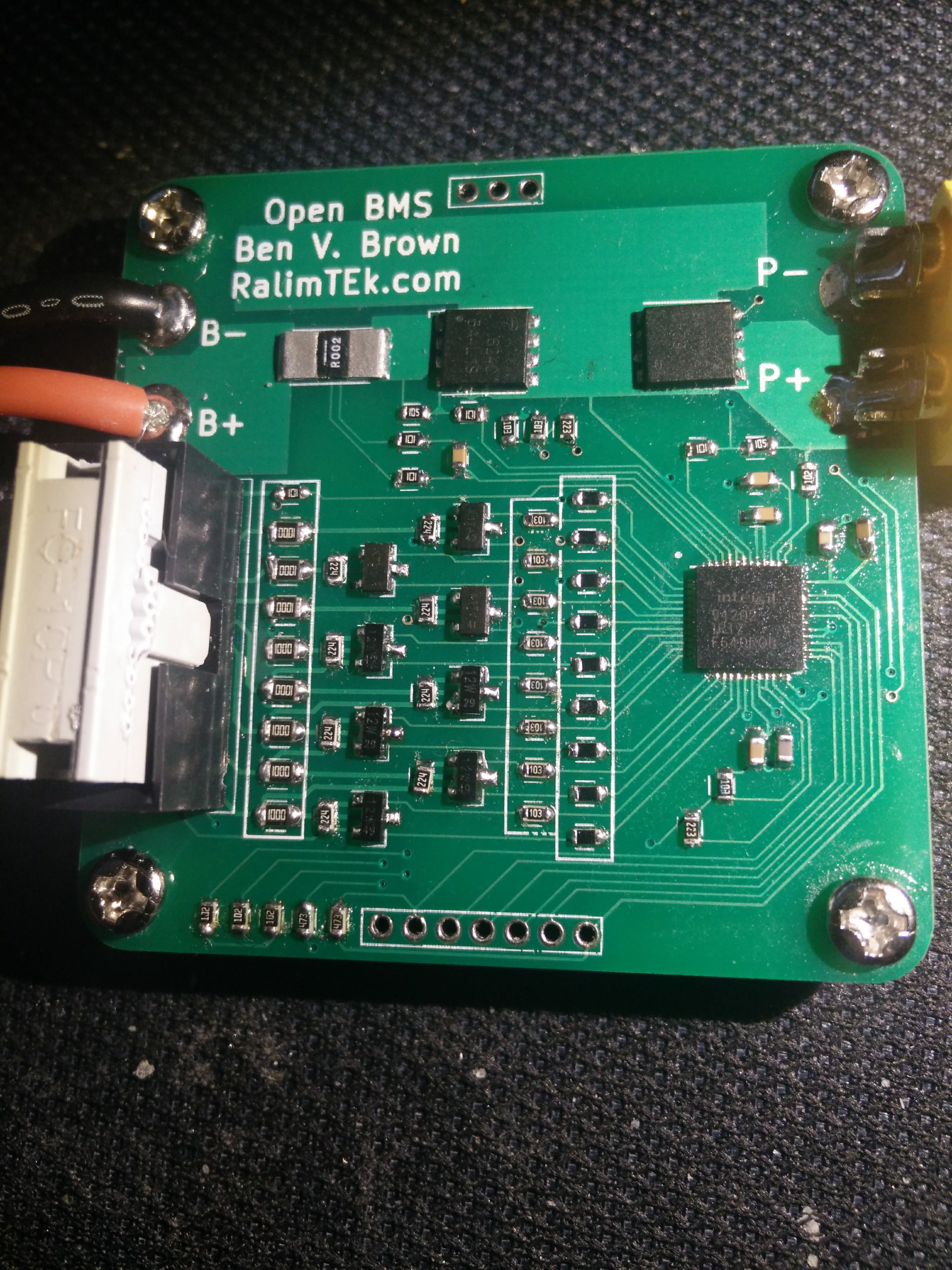
The system is designed around the ISL94202 being used to control the main BMS functions, and to allow standalone functionality. This is a relatively new part on the market, that integrates a 14Bit ADC, voltage reference, and monitoring engine etc. It also provides a 2.5V output that we use to run the front panel.
This BMS is being designed for smaller off-grid power or for portable applications (such as powering equipment in the field). Thus 3-8S are supported, which allows for 12V or 24V on both LiPoly and LiFePo4.
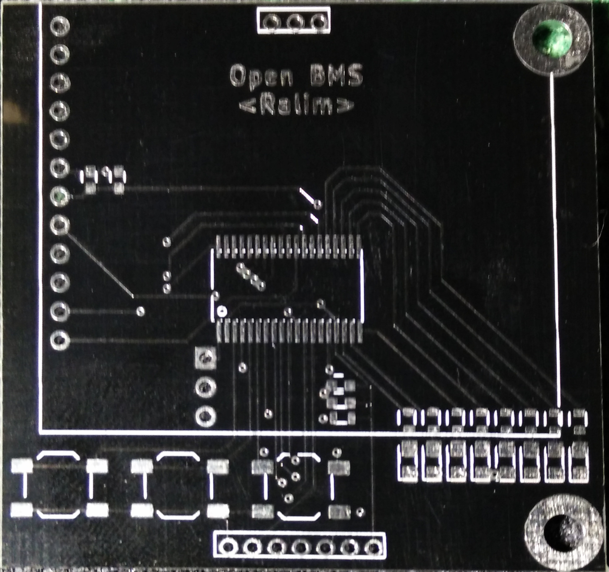
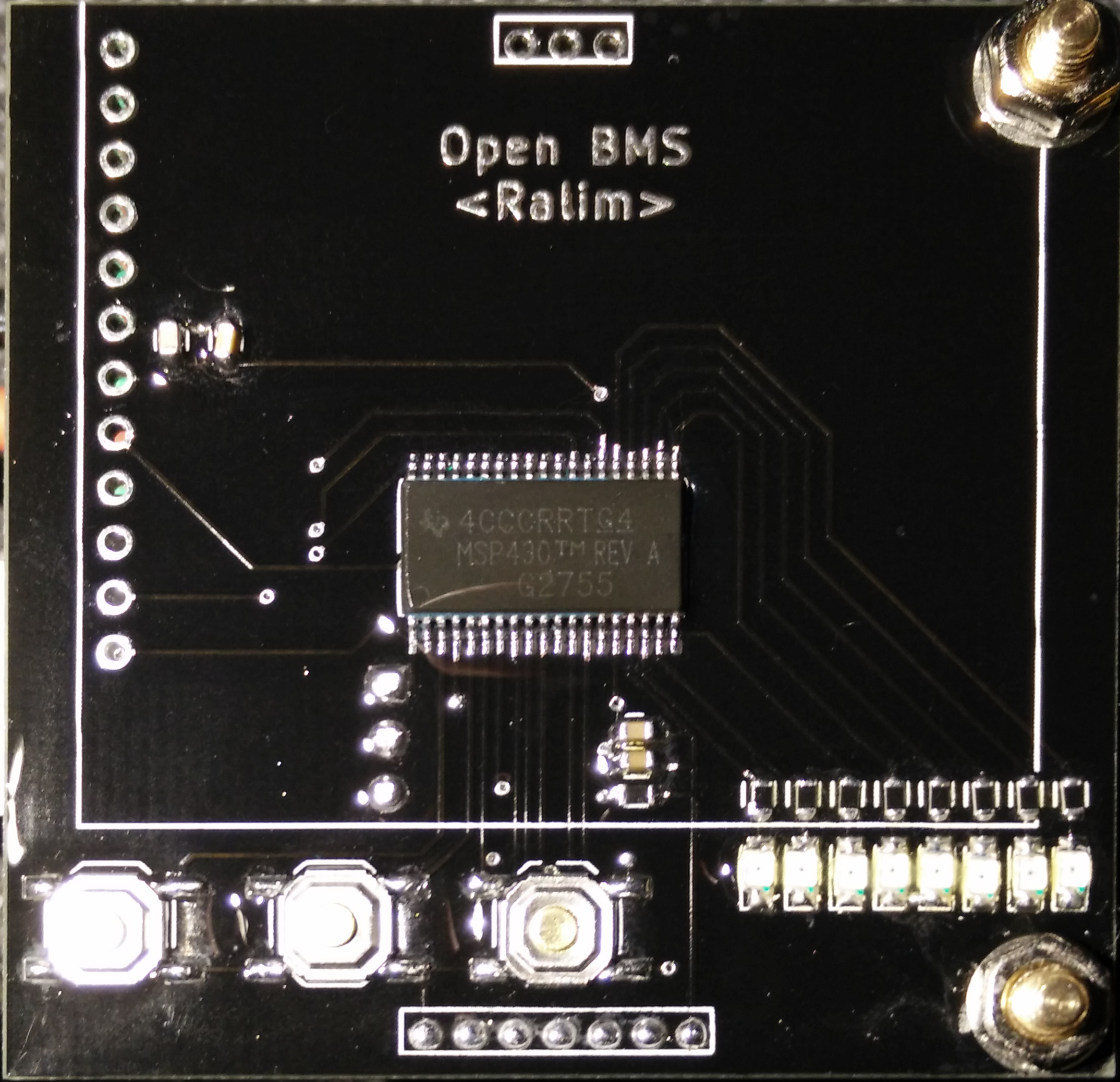
GUI
The GUI is built out of an MSP430 + 128x64 Graphical LCD. This allows for a flexible menu layout, leaving options open to future development. The MSP430 is very low power, so even operating modes where it has to stay active and out of sleep are not a major concern.
BMS
The most critical features really.
The unit maintains the cells in the pack by monitoring and balancing the cells as required, and providing the critical feature of controlling (dis)charge via the mosfets. This prevents the pack being damaged by over charge or over discharge conditions.
The balancing of the cells is software configurable and is performed with external fet's. Using around 80mA of balancing current is not massively high for large battery banks, but prevents any high temperatures occurring that could cause other issues. As the ISL monitors the cell voltages, if a cell is too high it will disconnect the charger while the balancing continues to run, allowing the balancing circuit to catch up. The use of external pass fets also allows any cell balancing, which prevents the issue that occurs on some of the TI chips, where adjacent cells cannot be balanced at the same time.


 Nguyen Vincent
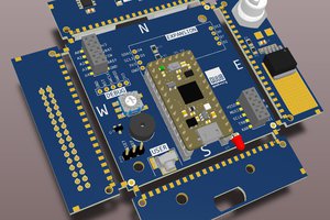
 rob
rob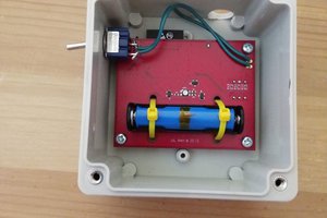

 Savo
Savo
How do you charge the batteries? Do you use P- P+ or will there be a dedicated port?