 Javier Isabel
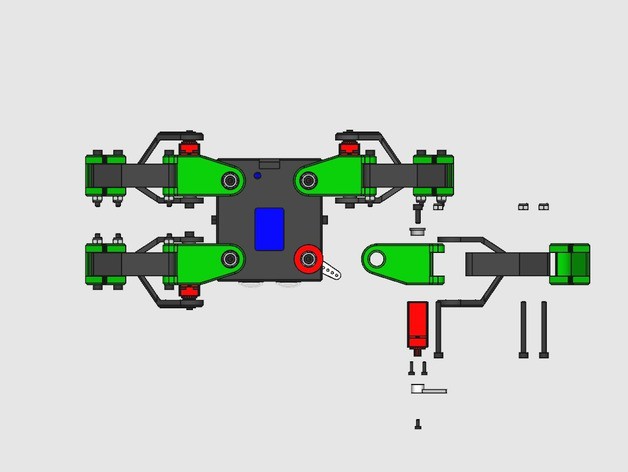
I has eight degrees of freedom, with two servos on each leg. Its legs perform a parallelogram mechanism, which let the foot be perpendicular to the floor on every movement. On the joints, there is room for F693ZZ bearings. These bearings fit nicely on PLA printed parts, and make the rotation smooth. However, they can be replaced with printed bushings too.
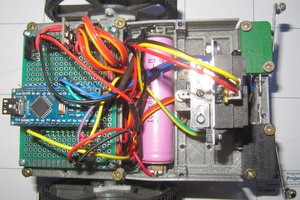
The main controller is an ESP8266 based board, the NodeMCU. It has its PWM outputs connected directly to the signal wire of the servos. The robot is powered by a two cell LiPo battery, that can be connected to the HV servos without the need of using any kind of voltage converter.
I have chosen for this robot some high speed servos. With them, Kame is able to walk making hopping gaits. Its control is based on oscillator algorithms. The oscillator method for designing walking patterns has been proved to work nicely on previous legged robot projects. I made libraries in Arduino and Python to manage oscillators and use them on robots like Maus (biped based on an Arietta G25 board) and Zowi (biped based on a BQ Zum board).
For more information, full FreeCAD sources and some code, you can visit its Github repository


 Audrey Robinel
 BINGOBRICKS
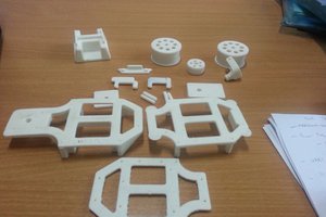
 shamylmansoor
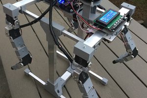
hello
I don't know if my sg90 servo motor should be restored to the default position before loading into the leg