• This is now built and working!

    matseng10/05/2018 at 16:53 0 comments

    After the years without access to a lab I finally got a new home lab and celebrated this with actually building this project as my entry to the RetroChallenge 2018/09 competition.

    I decided to keep the build blog in the GitHub repro for this project, so if you want to read about the build and testing you'll have to head over there..... 

    https://github.com/SmallRoomLabs/KCSviewer

  • Ring counter for the databits

    matseng07/20/2017 at 02:55 0 comments

    I now need to make eight pulses that coincides with the middle of each data bit so I can latch, or just temporarily store, the databits as they pass by. 

    First i tried a version with making a 3-bit binary counter out of T-flip flops and decode their Q's and /Q's from binary into separate output with a diode matrix.  This ended up a bit glitchy and requiring a lot of parts.

    So I went with a ring counter instead. It's not as "digital" as a binary counter and a decoder but it gets the job done with a decent amount of parts.

    I realised that I really don't need the 42ms monoflop that was used to inhibit the startbit detection during the reception of the databits so I removed that an replaced it with an edge triggered SR flipflop that is set by the startbit and reset by the last stage of the ring counter.

    The baudrate generator is (re-)started and synchronized when the SR flip flop is set so the issue of having the clock drifting in comparison to the incoming data is reduced.

    So now I've got a device that outputs 8 pulses in sync with the actual databits.

    The screenshot below shows three bytes of data (0x55, 0xAA and 0x18). To test the synchronization logic the third byte is slightly delayed.

    The green trace is the serial stream as output by the FSK demodulator. The cyan pulses are artificially made timing indicators to show where the middle of each data bit are. The red trace is the output of the second stage of the ring counter.

  • Startbit detector

    matseng07/14/2017 at 05:33 0 comments

    The next step is to detect the startbits of each character. It turned out to be surprisingly simple. Really nothing more than two monostables and two edge detectors is required.

    The FSK Demodulator block is the one from the previous posts. It outputs a serial data stream looking like the output from a regular UART. The datastream is idling at high level so when the startbit comes is will have a falling edge. This edge is detected by C2/Q4 and is triggering the first monostable that is set to have a timeout 1.66ms (half a bit period) so the output of this will have a falling edge at the midpoint of the startbit.

    Being the midpoint is important since we really want to take the samples of the databits at the middle of each bit-slot in case the clocks are a bit slow or fast.

    So this falling edge at the midpoint of the startbit is once more edge detected and is sent out as a short pulse as our startbit-marker in the circuit.

    This pulse is also triggering a second monostable with a timeout of 42.5 milliseconds giving an inhibit signal lasting into the stopbits of the current byte. This signal will block any more falling edges during the databits to retrigger the first monoflop that would cause false extra startbits.

    Here the red is the incoming serial data. At the same time the blue inhibit line goes high theres a green narrow (almost invisible) pulse signalling the middle of the startbit. This is followed by 8 alternating databits whose edgeds are blocked by the inhibit line (blue). A bit into the two stopbits the inhibit is deactivated making the circuit ready to to detect the next startbit.

  • Schematics cleanup

    matseng07/14/2017 at 02:50 0 comments

    Since there will be quite a few of the monostable flipflops in the design I made a subcircuit for a monostable. This will make things a bit cleaner and easier to follow.

  • Shaper & FSK decoder

    matseng07/13/2017 at 16:16 1 comment

    The V1 voltage source is "playing" a wav file with the data from my simulated KC tape. Since the output level is a bit too high I start of with a voltage divider bringing the level down to 250-300mV.

    For the amplifier/shaper/digitizer I'm simply using a long tailed differential amplifier-like contraption. It works kinda well, and I suppose it might be done in a better way but I'm not too picky here as long as the number of components are not going through the roof.

    We now have a decent digital waveform with a 0-5 volt swing.

    This is fed into a monostable flipflop that is reset whenever the incoming waveform is at high level. When the incoming waveform is going back to low the flipflop will timeout after about 300 us. Since a 2400 Hz tone is 208us low/208 us high, and a 1200 Hz tone is 416us low/416 high this monostable will never have a chance to timeout during a 2400 Hz tone, but will do it during the periods of 1200 Hz.

    So at this stage we have a steady level during a 2400 Hz tone, and a train of short pulses during the slower 1200Hz.

    Now we need to detect this pulse train and make it into one continuos level. This is done with yet another monostable flipflop. The pulses have a low period of 810us so the second monostable have a timeout of about 1100us.

    So as long as we have this pulse train the monostable will be retriggered and be active all the time, and when the pulse train stops it will timeout.

    The output of this a UART-like serial bitstream that is idling at a high level, and have a low level start bit.

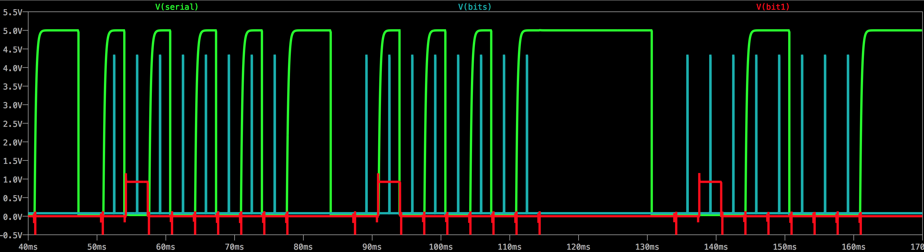
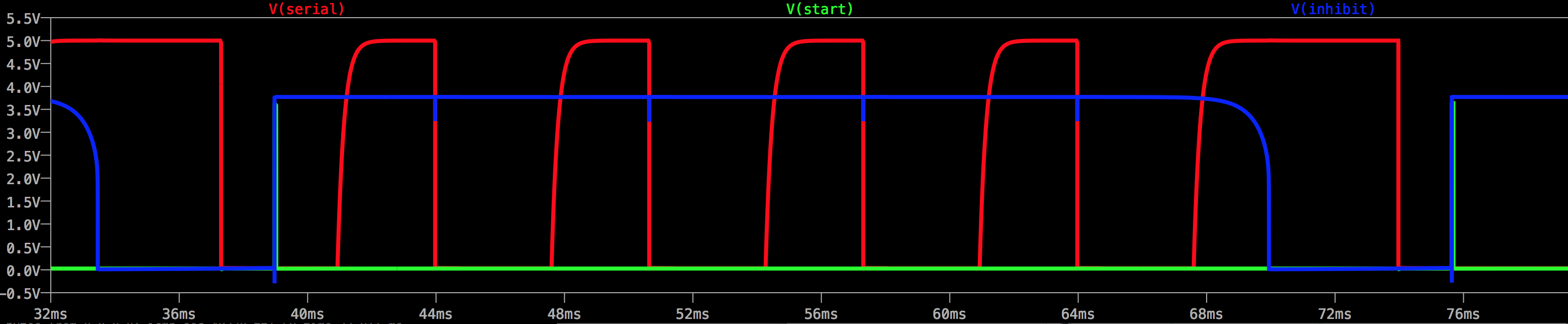
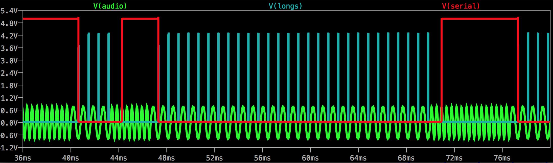
    The green trace is the incoming FSK audio staring with the idle level 2400Hz. At 40ms it switches over to 1200Hz for the startbit. The cyan traces is the timeout pulses from the first monoflop that is set to timeout whenever its input is low for more than 300us - which it is during the 1200Hz tone. These pulses are triggering the second monoflop to generate a low level (red) serial output. A soon as the input frequency goes back to 2400 Hz these pulses stop and the serial output goes low.
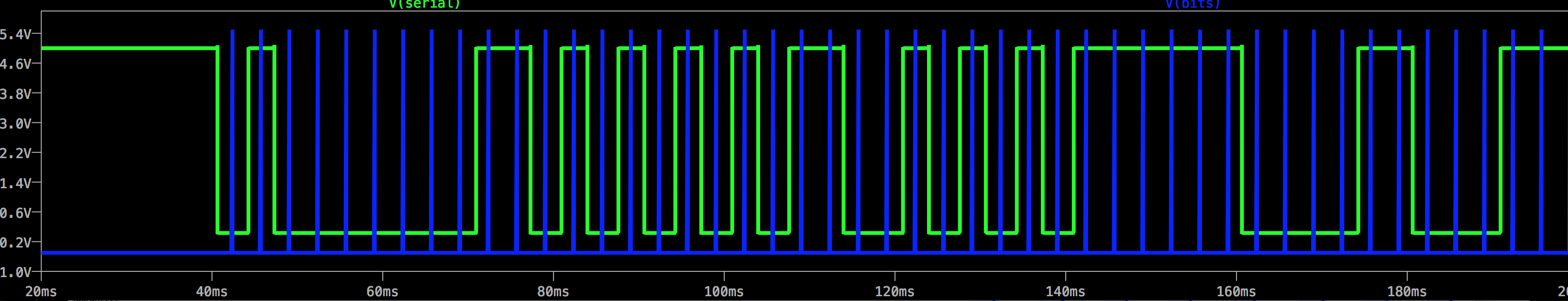
    So this screenshot shows a part of the initial idle state, followed by a low startbit, eight data bits where the LSB is high/1 followed by seven lows/0's, and then finally two high stopbits.

    The screenshot above shows the full serial output as taken from the KC.wav file . The serial data is green and a (debugging) signal in blue that shows the sample positions for the data bits. The data is 0x01 , 0x55, 0xAA then a short delay while keeping the idle level and finally a 0x18

  • Block diagram

    matseng07/13/2017 at 06:49 0 comments

    This is what I currently think will be needed.

    1. The audio from the cassette player needs to be amplified and shaped in to a proper square wave.
    2. The square wave will be decoded using either a PLL or simply a monoflop with a timeout set in the middle of the two frequencies.
    3. The startbit of resulting UART-like serial bitstream will be detected
    4. The startbit syncs a bitrate oscillator and resets the serial->parallel converter
    5. The S/P converter receives and stores the serial bitstream at the rate determined by the oscillator and outputs this to a 7-segment display

    The actual serial->parallel converter can either be done with a 8-bit SIPO Shift Register (pretty much like the 74LS595) or with 8 separate flip-flops/latches that are triggered one-by-one. The triggering can either be done with a 8-step ring counter or by a decoded 3-bit binary counter.

    Seems easy enough ;-) But will probably need quite a lot of transistors

  • KCS Audio generation

    matseng07/13/2017 at 04:37 5 comments

    First things first.... If I'm going to make a circuit to decode a Kansas City tape I'd better have some audio to play around with.

    So I wrote a small Python software (my first Python code ever) to create the sample tables for a single zero and one bits of audio. Then I put those into a bash script that pieces the samples together for a couple of bytes worth of data, writes that to a raw binary file and calls the sox utility to convert the raw sample into a proper .wav-file.

    The full file looks like this:

    Zooming in at around the start of data at 40 milliseconds into the file it looks like this - nice and clean sine waves.